1.2.1 Overview
BIOS扮演的最重要的角色之一就是启动系统。当PC被打开时,它的系统内存中是空的,它需要马上找到一条代码以启动机器。这些代码就在BIOS中,因为BIOS被放置在ROM中,所以即使系统内存的其它部分是空的,但BIOS中的程序却总是可以使用的。
这一节我们来看一看在Power-on之后的“硬件”Booting阶段,系统到底都做了些什么。同时,也看一看通过硬盘启动OS和软盘启动OS之间究竟存在着哪些不同。
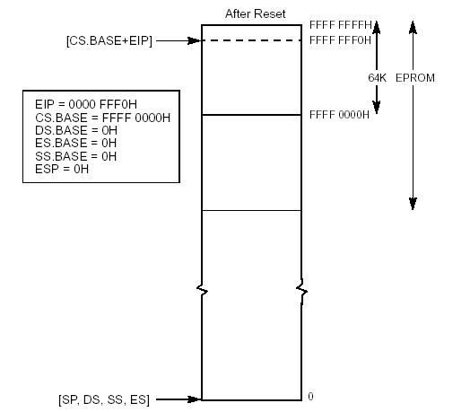
1.2.2 First Instruction Executed CPU从物理地址FFFFFFF0h取出并执行硬件Reset之后的第一条指令。这个地址到最大物理地址4 GB之间只有16
Bytes的空间,包含软件初始化代码的EPROM必须被影射到这个地址。在Real Mode下,地址FFFFFFF0h超过了1
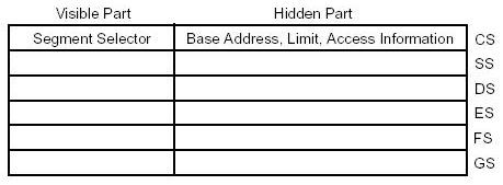
MB的物理地址范围。CS寄存器被分为两部分:可见的“Segment Selector”部分和隐藏的"Base Address"部分。 在Real Address Mode下,"Base Address"部分的值,等于将16-bit的"Segment
Selector"左移4-bit所形成的20-bit地址,"Segment Selector"部分并不参与物理地址的计算,在Real
Mode下,它仅仅被用来计算"Base Address"部分。而"Base Address"部分被真正的用于实际物理地址的计算。 在硬件Reset期间,CS中的"Segment Selector"部分被初始化为F000h,而"Base
Address"部分被初始化为FFFF0000h,这与上述的原则不相符,但没有关系,因为"Base
Address"已经有一个值了。所以,第一条指令的地址为Base Address + EIP = FFFF0000h + FFF0h =
FFFFFFF0。 EPROM中放置着PC厂商所编写的代码(BIOS),被影射在地址FFFFFFF0h的代码必须为一条"far jump"或者"far
call"指令或者产生一个中断,这样CS的"Segment Selector"的值将会被改变,从而"Base
Address"部分的值也按照上述计算原则被改变为BIOS代码的影射地址。 从此以后,BIOS Boot Sequence代码开始被执行。


1.2.3 System Boot Sequence
系统BIOS是机器被加电之后首先被运行的程序。我们下面看一看一个典型的Boot Sequence所包含的步骤,当然,由于硬件BIOS厂商的不同,这些序列会有一些不同,但下面所列的,是你的主机被加电之后,通常都会发生的序列。
总之,这个阶段有大量的事情要做,比如自检,初始化各种芯片,控制器,与端口;包括显示器,内存,键盘,软驱,串口等等;在这个过程中BIOS将检测到的数据放置于1K到2K的RAM,这个区域因此也被称为BIOS Data Area;同时还将中断向量以及BIOS程序运行所需要的Stack设置置于0到1K的RAM。最终,POST执行INT 19h中断,找到可以启动的磁盘,并将boot程序装入内存7C00h,并将控制权交给OS的boot程序。
1.2.4 OS Boot Sequence
当BIOS INT 19h被执行以后,系统进入OS Booting阶段。
下面定义几个程序段名称:
Name
Description
Size
limit
Master Booter
放置于Hard disk的第一个扇区(即MBR),用于装载boot block的程序。
466 bytes
Boot Sector
放置与Floppy的第一个扇区,或者Hard disk的某一分区的第一个扇区的用于装载Secondary boot,或其它程序的可运行程序。
512 bytes
Secondary Boot
放置于非Floppy/Hard disk的第一个扇区,以及Hard disk的任意分区的第一个扇区之外的任意其它位置,用于装载OS,或其它程序的可运行程序。
no
limit
当用硬盘启动OS的时候,以上调用顺序为 MB -> BS -> SB -> OS;
当用软盘启动OS的时候,以上调用顺序为 BS -> SB -> OS。
1.2.4.1 硬盘启动
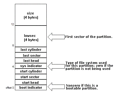
硬盘的第一个扇区(sector)被称作MBR(Master Boot Record)。由于硬盘可以有多个分区,所以在MBR上,不仅放置着用于启动的可执行代码master boot,还放着磁盘分区表(DPT),占用66个字节,所以MBR中的可执行代码必须在512 - 66 = 446个字节以内。
Offset
Content
Size
0h
Master booting
program
max 466 bytes
01BEh
Disk Partition Table
64 bytes
01FEh
Signature (HEX 55
AA)
2
bytes
Table 1.2.1- MBR Layout
Offset
Content
Size
01BEh
Partition 1 data
table
16 bytes
01CEh
Partition 2 data
table
16 bytes
01DEh
Partition 3 data
table
16 bytes
01FEh
Partition 4 data
table
16
bytes
Table 1.2.2 - DPT Layout
Offset
Content
Data
Type
00h
boot indicator
byte
01h
beginning sector head
number
byte
02h
beginning sector (2 high bits
of cylinder #)
byte
03h
beginning cylinder# (low order
bits of cylinder #)
byte
04h
system indicator
byte
05h
ending sector head
number
byte
06h
ending sector (2 high bits of
cylinder #)
byte
07h
ending cylinder# (low order
bits of cylinder #)
byte
08h
number of sectors preceding
the partition
dword(4 bytes)
0Bh
number of sectors in the
partition
dword
Table 1.2.3 - Layout of Partition Data Table
Boot indicator (BYTE)
00 - non-bootable partition
80 - bootable partition (one partition only)
System Indicator (BYTE)
00 - unknown operating system
01 - DOS with 12 bit FAT, 16 bit sector number
02 - XENIX
04 - DOS with 16 bit FAT, 16 bit sector number
05 - DOS Extended partition (DOS 3.3+)
06 - DOS 4.0 (Compaq 3.31), 32 bit sector number
51 - Ontrack extended partition
64 - Novell
75 - PCIX
DB - CP/M
FF – BBT
Signature
Hex 55AA marks the end of valid boot sector.
This is also required in each of the partition boot records.

What does master booter should do?
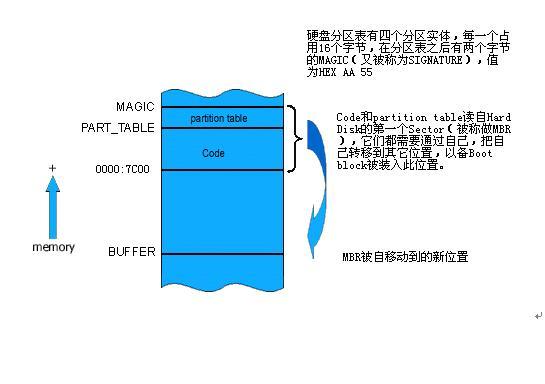
INT 19会将MBR的512 bytes load到内存0x7c00中,然后JUMP到0x7c00处,开始执行MBR的可执行程序master booter,Master booter最起码需要做这些事情:
- 检测MAGIC(Signature)是否为合法值(Hex 55AA);
-
将自己移动到其它位置,将0x7C00到0x7c00+512K的空间让出来,以备其后将boot sector程序装入这个位置,这样才能和直接从软盘直接装入boot sector程序相一致;具体移动到什么位置,则根据设计而定,理论上,可以移动到任何非冲突位置(即没有被预留为其它程序所用的位置);但一般情况下,都是在0X000800至0X0A0000之间寻找一端空间存放。
-
查看分区表,将被设为活动的分区的第一个Sector装入0X7C00的位置,正常的情况下,此Sector放置的就是boot sector程序;
-
最终,master booter跳转到0X7C00的位置,开始执行boot sector。
