We have included a wizard in the GPD plugin to create a jBPM project. We have opted to create a project containing based on a template already containing a number of advanced artifacts that we will ignore for this section. In the future we will elaborate this wizard and offer the possibility to create an empty jBPM project as well as projects based on templates taken from the jBPM tutorial.
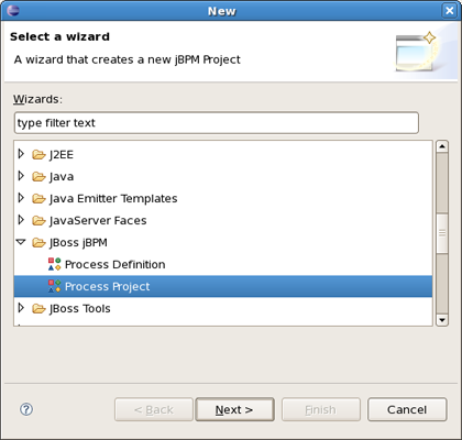
To create a new jBPM project using the project creation wizard, we select File >New Project... and in the New Project dialog, we select JBoss jBPM > Process Project :
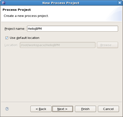
Clicking Next brings us to the wizard page where we have to specify the name and location for the project. We choose for example Hello jBPM as the name and accept the default location.
Clicking on Finish results in the project being created. The wizard creates four source folders: one for the processes ( src/main/jpdl ), one for the java sources ( src/main/java ), one for the unit tests ( src/test/java ) and one for the resources such as the jbpm.properties and the hibernate.properties files ( src/main/config ). In addition a classpath container with all the core jBPM libraries is added to the project
Looking inside the different source folders will reveal a number of other artifacts that were generated, but we will leave these untouched for the moment. Instead, we will look at another wizard that enables us to create an empty process definition.
When the project is set up, we can use a creation wizard to create an empty process definition. Bring up the New wizard by clicking the File > New > Other... menu item. The wizard opens on the Select Wizard page.
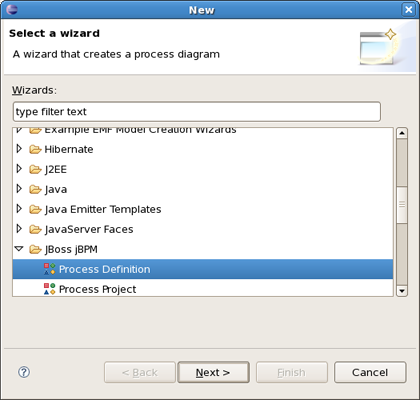
Selecting the JBoss jBPM category, then the Process Definition item and clicking on the Next button brings us to the Create Process Definition page.
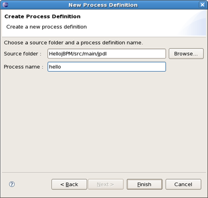
We choose hello as the name of the process archive file. Click on the Finish button to end the wizard and open the process definition editor.
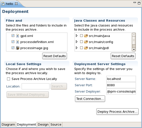
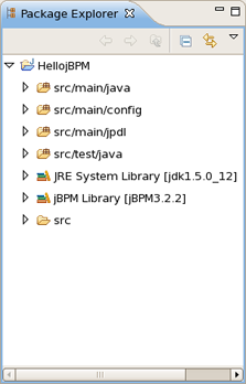
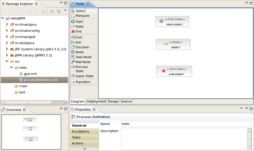
You can see in the Package Explorer that creating a process definition involves creating a folder with the name of the process definition and populating this folder with two .xml files : gpd.xml and processdefinition.xml .
The first of these two contains the graphical information used by the process definition editor. The processdefinition.xml file contains the actual process definition info without the graphical rendering info. At present, the GPD assumes that these two files are siblings. More sophisticated configuration will be supported later.
We will create a very simple process definition, consisting of a begin state, an intermediate state and an end state.
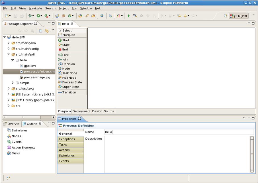
To make the configuration of actions much easier it's better to use the jPDL perspective. It provides the tabbed Properties Editor which allows to configure all the relevant properties of the current selected item.
Select respectively Start , State and End on the tools palette and click on the canvas to add these nodes to the process definition. The result should look similar to this:
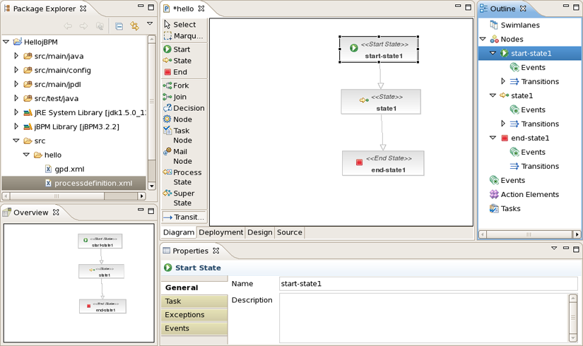
We will connect the nodes with transitions. Select the Transition tool in the tools palette and click on the Start node, then move to the State node and click again to see the transition being drawn. Perform the same steps to create a transition from the State node to the End node. The result will look like:

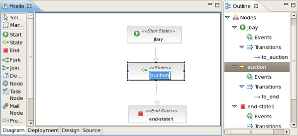
You can see an outline of the process being drawn in the JBDS outline view if it is visible (if not select Window > Show view > Outline ). It is presented as the classical tree view. Also you can use Overview that comes as a scrollable thumbnail.
If the JBDS Properties view is visible (if not select Window > Show view > Properties ), the relevant properties of the selected item are shown. Some of these properties may be directly editable in the properties view. An example of a directly editable property is the name property of the process definition. As you can see in the next figure, the name property of the process definition can be changed to jbay . You can also write a description for this property.
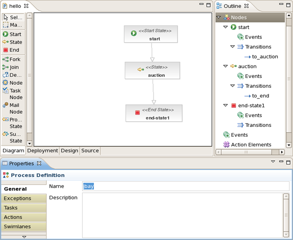
Let's change the name of the first transition to to_auction . We repeat this name change for the second transition and name it to_end .
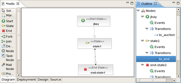
Some properties can be directly edited in the graphical editor. One example of this is the Name property of nodes. You can edit this directly by selecting the node of which you want to change the name and then click once inside this node. This enables an editor in the node. We change the name of the node to auction .
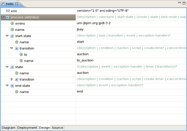
Now that we have defined a simple process definition, we can have a look at the xml that is being generated under the covers. To see this xml, click on the source tab of the process definition editor.
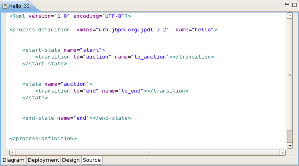
This source tab is editable, so if you know your way around in jpdl, you can create or tweak your process definitions directly in the xml source.
The file is also editable in Design view as you can see in the next picture: