Business Object Document Message Architecture
In order to achieve interoperability
between disparate systems, disparate companies and disparate supply chains, there
must be a common horizontal message architecture that provides a common
understanding for all.
Once a horizontal messaging
architecture has been agreed upon these messages can be sequenced together to
form scenarios. Scenario can provide the detail step-by-step exchange of
information needed to perform specific tasks. These tasks can be simple or
complex. As such, the scenario describing them may be simple or complex.
Complex scenarios may reuse one or more simple scenarios.
The Open Applications Group
Integration Specification (OAGIS) provides example scenarios that can be used
as a starting point for integration. By identifying a scenario that most
closely matches your needs, it is possible to identify the messages needed to
achieve your needs.
The rest of this chapter describes
the architecture of the Open Applications Group Integration Specifications,
Business Object Document (BOD). The BOD
is a common horizontal message architecture. BODs are the business messages or
business documents that are exchanged between software applications or
components; between companies; across supply chains; and between supply
chains.
In order to do this the BOD must be
able to inform the receiving system what kind of message to expect in the data
area. Often there is a two-way interaction between a sender and receiver, for
this reason, the BOD needs to be able to communicate status and error
conditions. It is also necessary to provide for multiple actions on a common
business object (Noun). For this reason the OAGIS BODs have been designed to
make use of a common Nouns that a given action (Verb) may be applied. As
different industries have different needs OAGIS must be extensible in order to
allow industry verticals to plug in information that is needed in their industry.
For this reason the BODs have been designed to be extensible, while providing a
common architecture and content for integration.
The BOD Message Architecture is
independent of the communication mechanism. It can be used with simple
transport protocols such as HTTP and SMTP but it also can be used in more
complex transport protocols such as SOAP, ebXML Transport and Routing, or any
other Enterprise Application integration system.
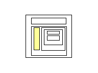
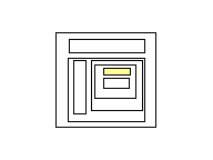
A BOD graphically consists of the
following:
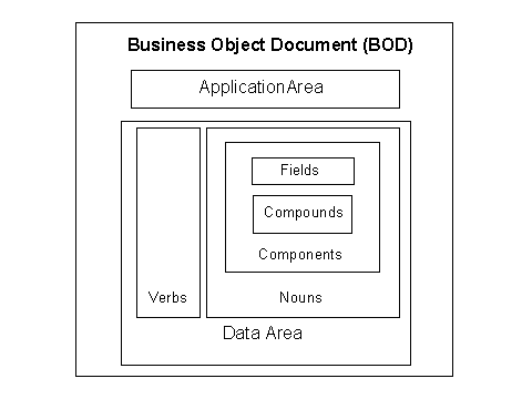
These areas are defined as follows:
·
The
outermost layer of the BOD identifies the Verb, Noun, revision and runtime
environment (Test or Production in which the BOD instance is to be used.)
·
Application
Area – Application Area communicates information that can be used by the
infrastructure to communicate the message.
·
Data
Area – The Data Area carries the business specific payload or data being
communicated by the BOD.
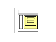
·
Verbs
– Verb identifies the action being performed on the specific Noun of the BOD.
·
Nouns - Nouns identify the business specific data
that is being communicated (i.e. PurchaseOrder, SalesOrder, Quote, Route,
Shipment, etc.) They are comprised of Components, which are described below.
Nouns are extensible in order to support the needs of specific vertical
industries.
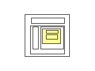
·
Components
– Components are extensible building blocks of a Noun (i.e. PurchaseOrder
Header, PurchaseOrder Line, Address, etc.). They are comprised of compounds and
fields, which are described below. Components are extensible.
·
Compounds
– Compounds are basic, shared building blocks that are used by all BODs (i.e.
Quantity, Amount, etc.). They are extensible through contextual use but not
with additional fields (i.e. OrderedQuantity, ShippedQuantity,
BackOrderedQuantity).
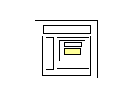
·
Fields
– Fields are the lowest level elements defined in OAGIS. Fields are fundamental
elements that are used to create Compounds and Components. (i.e. Description,
Name, etc.).
Note: The graphics within this document are from XML Spy. They
are shown here as a way for the reader to visually see the constructs being
defined. The Open Applications Group does not recommend individual tools.
However, OAGI does recommend using an XML Integrated Development Environment
(IDE) when working with complex XML Schema languages like OAGIS.
1.1 Business Object Document
The Verb identifies the action that
the Sender application wants the Receiver application to perform on the Noun.
OAGIS defines a standard list of Verbs and Nouns that are needed in most supply
chain and manufacturing integration scenarios.
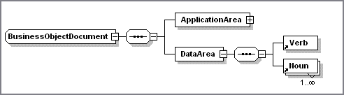
The general structure for all of
Business Object Documents is shown in the following figure.
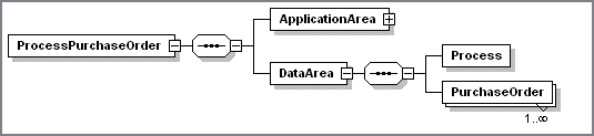
For a given Business Object Document,
the generic names (BusinessObjectDocument, Verb, Noun) are replaced by specific
names (ProcessPurchaseOrder, Process, and PurchaseOrder):
The child elements of a
BusinessObjectDocument are:
·
ApplicationArea
·
DataArea.
The ApplicationArea and DataArea
separate the application-specific information common to all BODs from the information
that is specific to each BOD. Each is discussed in more detail in the following
sections
In addition to these child elements,
each BOD contains four attributes, the BOD's releaseID, versionID, systemEnvironmentCode,
and languageCode.
Release ID
Release ID is used to identify the
release of OAGIS that the BOD belongs. For the BODs from OAGIS 9.0 the value of
this attribute will be “9.0”. The release ID is a required attribute of the
BOD.
Version ID
Version ID is used to identify the
version of the Business Object Document.
Each BOD has its own revision number to specifically identify the level
of that BOD, not just the release ID of OAGIS. The specific BOD version number
is documented in each chapter of OAGIS. The outermost element name no longer
includes the version number; it is instead now carried as an attribute of the
BOD. The version ID attribute is an optional attribute of the BOD.
System Environment Code
The System Environment Code is used to
identify whether this particular BOD is being sent as a result of a test or as
production level integration. Often times as new systems are brought online
testing must be performed in a production environment in order to ensure
integration with existing systems. This attribute allows the integrator to flag
these test messages as such. The environment attribute is an optional attribute
of the BOD.
Language Code
The languageCode attributes indicates the language of the data being
carried in the BOD message. It is possible to override the BOD level language
for fields that may need to carry multi-lingual information. Examples of this
are Notes and Description.
XML supports only one encoding for an XML message as such the languages
carried within a BOD are limited to the set that the XML encoding can support.
1.2 Application Area
The ApplicationArea carries
information that an application may need to know in order to communicate in an
integration of two or more business applications. The ApplicationArea is used
at the applications layer of communication. While the integration frameworks
web services and middleware provide the communication layer that OAGIS operates
on top of.
As indicated in the graphic below
each BOD contains one unique ApplicationArea
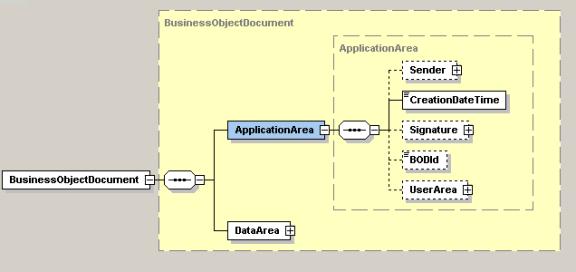
The ApplicationArea serves four main purposes:
1. To identify the sender of the
message.
2. To identify when the document was
created.
3. To provide authentication of the
sender through the use of a digital signature, if applicable.
4. To uniquely identify a BOD instance.
The BODId field is the Globally Unique Identifier for the BOD instance.
The ApplicationArea is comprised of
the following elements:
-
Sender
-
Creation – (date and time)
-
Signature
-
BODID
-
UserArea
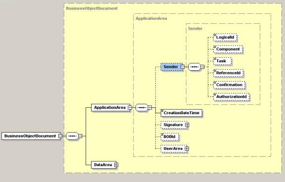
Sender
The Sender identifies characteristics
and control identifiers that relate to the application that created the
Business Object Document. The sender
area can indicate the logical location of the application and/or database
server, the application, and the task that was processing to create the BOD.
The Sender area also provides the ability to create an audit trail to
allow users to drill down from their Receiving business application to the
information used to complete the business transaction being communicated in the
BOD.
In today’s business environments and advanced technology frameworks a
single BOD may be routed to multiple destinations or receivers. For this
reason, it is not feasible for the sending system to “know” all of the possible
destinations of a BOD. For this reason the Open Applications Group has made a
conscious decision NOT to include a Receiver in the ApplicationArea. This is
left to the middleware or infrastructure framework to ensure delivery to all
locations that are interested in the content of the BOD.
The Sender is comprised of the
following information:
-
LogicalID
-
ComponentID
-
TaskID
-
ReferenceID
-
ConfirmationCode
-
AuthorizationID
Logical ID
The Logical Identifier element
provides the logical location of the server and application from which the
Business Object Document originated. It can be used to establish a logical to
physical mapping, however its use is optional.
Each system or combination of systems
should maintain an external central reference table containing the logical
names or logical addresses of the application systems in the integration
configuration. This enables the logical
names to be mapped to the physical network addresses of the resources needed on
the network.
Note:
The technical implementation of this Domain Naming Service is not dictated
by this specification.
This logical to physical mapping may
be done at execution time by the application itself or by a middleware
transport mechanism, depending on the integration architecture used.
This provides for a simple but
effective directory access capability while maintaining application
independence from the physical location of those resources on the network.
Component ID
The Component ID provides a finer
level of control than Logical Identifier and represents the business application
that issued the Business Object document.
Its use is optional.
The Open Applications Group has not constructed the list of valid Component names. A suggestion for naming is to use the application component names used in the scenario diagrams in section two of OAGIS. Example Components may be “Inventory”, or “Payroll”.
Task ID
The Task ID describes the business event that initiated the need for the Business Object Document to be created. Its use is optional. Although the Task may differ depending on the specific implementation, it is important to enable drill back capability. Example Tasks may be “Receipt” or “Adjustment”.
Reference ID
Reference ID enables the sending application to indicate the instance identifier of the event or task that caused the BOD to be created. This allows drill back from the BOD message into the sending application. The may be required in environments where an audit trail must be maintained for all transactions.
Confirmation Code
The Confirmation Code request is an
option controlled by the Sender business application. It is a request to the receiving application
to send back a confirmation BOD to the sender. The confirmation Business Object
Document may indicate the successful processing of the original Business Object
Document or return error conditions if the original Business Object Document
was unsuccessful.
The confirmation request has the following valid values:
|
Never |
No confirmation Business Object
Document requested |
|
OnError |
OnError send back a confirmation
Business Object Document only if an error has occurred |
|
Always |
Always send a confirmation Business
Object Document regardless |
Authorization ID
The Authorization Identifier describes the point of entry,
such as the machine or device the user uses to perform the task that caused the
creation of the Business Object Document.
The Authorization Identifier is used as a return routing mechanism for a
subsequent BOD, or for diagnostic or auditing purposes. Valid Authorization Identifiers are
implementation specific. The
Authorization Identifier might be used for authentication in the business
process. As an example, in the case of
Plant Data Collection, the Authorization Identifier is used to fully define the
path between the user of a hand held terminal, any intermediate controller and
the receiving application.
In returning a BOD, the receiving application would
pass the Authorization Identifier back to the controller to allow the message
to be routed back to the hand held terminal.
CreationDateTime
CreationDateTime is the date time
stamp that the given instance of the Business Object Document was created. This date must not be modified during the
life of the Business Object Document.
OAGIS Date time type supports ISO
Date Time format.
Signature
If the BOD is to be signed the signature element is included, otherwise
it is not.
Signature will support any digital signature that maybe used by an
implementation of OAGIS. The qualifyingAgency identifies the agency that
provided the format for the signature.
This element supports any digital signature specification that is
available today and in the future. This is accomplished by not actually
defining the content but by allowing the implementation to specify the digital
signature to be used via an external XML Schema namespace declaration. The
Signature element is defined to have any content from any other namespace.
This allows the user to carry a digital signature in the xml instance of
a BOD. The choice of which digital signature to use is left up to the user and
their integration needs.
For more information on the W3C’s XML Signature specification refer to: http://www.w3.org/TR/xmldsig-core/.
BODID
The BODID provides a place to carry a Globally Unique Identifier (GUID)
that will make each Business Object Document uniquely identifiable. This is a critical success factor to enable
software developers to use the Globally Unique Identifier (GUID) to build the
following services or capabilities:
1.
Legally
binding transactions,
2.
Transaction
logging,
3.
Exception
handling,
4.
Re-sending,
5.
Reporting,
6.
Confirmations,
7. Security.
How do I get a GUID:
·
Sun’s
iPlanet Application Server provides the ability to generate a GUID, see http://docs.iplanet.com/docs/manuals/ias/60/sp3/JavaProgGuide/jpgdeplo.htm
·
The
following link provides example VisualBasic code to create a GUID generating
component, see http://www.aspzone.com/articles/john/GUIDGen/BuildaGUIDGeneratingComponent.asp
·
The
following link shows a simple VisualBasic generator, see http://www.vbaccelerator.com/codelib/tlb/guid.htm
·
The
following link provides an example of how to generate a GUID in
1.3 Data Area
The Data Area (DataArea) of the
Business Object Document contains the instance(s) of data values for the
business transaction. For example, to send a Purchase Order or Orders to a
business partner, the Data Area will contain Verb (the action) and the Noun
(the object) on which the action is to be performed.
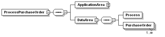
The DataArea contains a single verb
and one or more occurrences of a noun. This is shown in the examples above
where the repeating PurchaseOrder element indicates that 1 or more instances of
the “PurchaseOrder”s are to be “Process”ed.
1.4 Verb
The Verb is the action to be applied to the object (the Noun).
Examples of Verbs include Cancel, Add, Process, and Synchronize. Any additional
information that is exclusively related to the action is also stored with the
Verb.
For example a Process verb indicates that it is acknowledgeable and
confirmable.
1.5 Noun
Noun is the object or document that is being acted upon. Examples include
PurchaseOrder, RequestForQuote, and Invoice. Nouns are extensible within OAGIS,
meaning that they can include content that was not originally designed by OAGI.
There are different types of verbs or actions that can be performed on a
PurchaseOrder; as such the base Noun (e.g. PurchaseOrder) contains all of the
information that might be present on a PurchaseOrder. The instantiation of each
of the possible verb and noun combinations then further defines what must be
provided to perform the intended transaction. For example in a
ProcessPurchaseOrder transaction business partners and line item data must be
provided, whereas in a CancelPurchaseOrder only the order identifier needs to
be provided.
Nouns are extensible within OAGIS meaning that additional content
(fields, compounds and components can be added to an existing Noun). This
additional content can be defined external to OAGIS and added through the use
of In-Line extensions. In-Line extensions will be discussed later in this
document.
1.6 Components
Components are the large-grained building blocks of a Noun. Components
are extensible within OAGIS. Components consist of other Components, Compounds,
and Fields examples of Components include: PurchaseOrder Header, Party, and
Address.
Components are extensible within OAGIS meaning that additional content
(fields, compounds and components can be added to an existing Component). This
additional content can be defined external to OAGIS and added through the use
of In-Line extensions. In-Line extensions will be discussed later in this
document.
The instantiation of the Component identifies the OAGI recognized fields,
compounds, and other components that must be present to support the intended
business transaction on a BOD-by-BOD basis.
1.7 Compounds
Compounds are a logical grouping of
fields (low level elements) that are used across all BODs.
Examples include Amount, Quantity,
DateTime, and Temperature. Unlike Components, Compounds cannot be extended to
include new data content.
1.8 Fields
Fields are the lowest level elements used in OAGIS Components and
Compounds. These fields maybe based on either an OAGIS-defined type or a
user-defined type.
1.9 Fields vs. Compounds
In the instantiation of OAGIS in XML Schema the distinction between
fields and compounds become less defined. This is due to the fact that XML
Schema provides a richer type system than that offered by DTDs, in fact a type
system did not exist prior to the approval of the W3C XML Schema Recommendation (May, 2001). This allows the expression of dates
and quantities in lower-level elements. With the XML Schema type system the
need for Fields and Compounds is replaced by the combination of:
·
Built-in
datatypes, based on ISO standards, e.g. for dates, times, and decimal numbers.
·
Simple
User-definable types, are user-constrained versions of the standard types
·
Complex
User-definable types, which are user-defined structures built up from other
simple and complex type
Since OAGIS is independent from the language used to instantiate it, the
concepts of Compounds and Fields remain constant. However, they are both
derived from Types in XML Schema. The XML Schema instantiation of OAGIS defines
both compounds and fields as types. For this reason they are both defined in a
single file “Types.xsd”, whereas the XML DTD instantiation defines them in
separate files.
2.0 Extensions
While it is important to clearly define the messages to be passed between
business partners and between business applications, it is not possible to
identify all of the possible information that may be needed in every given
situation. It is also not possible to completely identify the unique
characteristics that may provide value for a given customers implementation.
In other words there are always going to be extension needed such that a
company can communicate its unique needs. These may be in the form of
additional fields or in the form of additional values for a given field(s).
For this reason OAGIS is designed to be extended.
OAGIS can be extended in the following ways:
·
UserArea Extensions – UserArea extensions provide an
optional element within each OAGIS defined component that may be used by an
implementer to carry any necessary additional information. For example, it may
be necessary to carry field XYZ in the Header of a ProcessPurchaseOrder BOD in
order to meet the unique customer demands. This can easily be accomplished by
defining the field XYZ in a XML Schema file and reference this file via a
namespace in the XML instance of the BOD and carrying the extended field in the
UserArea of the ProcessPurchaseOrder’s Header. As long as this additional XML
Schema file is reference able, the extension can be validated.
·
Overlay Extensions – Overlay extensions provide users
the ability to have their extensions appear within OAGIS defined components. In
order to add elements a user must extend the OAGIS types within their own
namespace. This is accomplished by creating a series of files that are similar
to the OAGIS resource files. By doing this it is possible for users to enforce
additional restrictions and/or add additional elements to OAGIS defined Nouns
or Components. It is also possible for users to provide additional constraints
in their own XSL constraints, which may then be applied, to OAGIS.
For more on how to extend OAGIS, please see the OAGIS XML Schema
Extensions white paper.
NOTE: Regardless of whether the
extensions are in-line or in the UserArea, they must use namespaces qualified
element names. Unqualified elements based on namespace types, are not allowed.
2.1 UserArea Extensions
A UserArea is a special field that identifies
where the user’s unique data for a particular implementation may be provided.
For example it may be necessary to carry customer, vendor or project
extensions. The UserArea is provided as a place to carry these additional
elements.
The UserArea is defined by embedding XML tags for
each new Field Identifier, new Compound or new Component needed within this
area. When a new Field Identifier or a
new Compound is determined to be necessary but was not included in the OAGIS
specification, the project team for the specific integration project can
develop new tags. These new tags can be
used to describe the fields and compounds within the UserArea.
The UserArea
may contain multiple fields,
compounds or components coded in this way.
Specific instructions for using the
UserArea
are defined in the OAGIS Extensions
white paper OAGIS Extensions with XML 1.0 and OAGIS Extensions with XML Schema
(coming soon).
The UserArea is implemented as an unrestricted
ANY element, allowing any content to appear in the UserArea.
The optional UserArea is specified in all Components. It
always appears after any OAGIS-defined Components, Compounds, or Fields in a
Component. The only things that will appear after the UserArea are Overlay
extensions. XML Schema requires that any extensions be appended to the end of
the currently defined type.
2.2 Overlay Extensions
In order to provide the additional functionality required by vertical
industries, the XML Schema instantiation of the OAGIS Message Architecture
supports In-Line extension of OAGIS. This is accomplished through the use of
the XML Schema ability for types to extend other types and through the use of
Substitution Groups.
It is possible to extend, the content of any OAGIS Noun or
Component. Doing so appends new element content to an existing Noun or
Component. The following example shows how a ProcessPurchaseOrder BOD maybe
extended by a fictions vertical industry, IndustryA, to include additional
fields that maybe needed within the it’s vertical.
<ProcessInvoice xmlns="http://www.oagi.net/oagis/ia" xmlns:oa="http://www.openapplications.org/oagis" xmlns:xsi="http://www.w3.org/2001/XMLSchema-instance" xsi:schemaLocation="http://www.oagi.net/oagis/ia
../BODs/ProcessInvoice.xsd" revision="001" environment="Production" lang="en-US">
<oa:ApplicationArea>
<oa:Sender>
<oa:LogicalID>String</oa:LogicalID>
<oa:ComponentID>String</oa:ComponentID>
<oa:TaskID>String</oa:TaskID>
<oa:ReferenceID>String</oa:ReferenceID>
<oa:ConfirmationCode>0</oa:ConfirmationCode>
<oa:AuthorizationID>String</oa:AuthorizationID>
</oa:Sender>
<oa:CreationDateTime>2001-12-17T09:30:47-05:00</oa:CreationDateTime>
<oa:Signature qualifyingAgency="String"/>
<oa:BODId>String</oa:BODId>
<oa:UserArea/>
</oa:ApplicationArea>
<DataArea>
<oa:Process/>
<Invoice>
<Header>
<oa:DocumentIds>
<oa:CarrierDocumentId>
<oa:Id/>
</oa:CarrierDocumentId>
</oa:DocumentIds>
<oa:Status>
<oa:Code/>
</oa:Status>
<TimeCard/>
</Header>
<oa:Line/>
<GrandTotal/>
</Invoice>
</DataArea>
</ProcessInvoice>
Note: These
extensions, while providing new elements in OAGIS, are distinguished from core
OAGIS content by the presence of a namespace identifier. In this case, the
default namespace is used to identify Industry A extensions prefix. OAGIS
defined elements are identified by the “oa:” namespace.
A detailed explanation of how to accomplish this and how it
works can be found in the OAGIS XML Schema Extension white paper.
While it is possible to carry externally defined element within the
UserArea, OAGI recommends using Overlay extensions to add additional
information to OAGIS.
While XML Schema provides a view powerful mechanism for
validating types and structures. It does not provide a good mechanism for
applying rules and constraints that may differ from implementation to
implementation. For this reason the decision was made to separate the type and
structure validation from the rules and constraint validation. With the
structure and type being provided by XML Schema and the rules and constraints
being provided by XSL. More specifically XPath but since there are many
different XSL processors available and no simple XPath processors and XPath is
a part of XSL.
This allows OAGI to define the required fields that our constituency agrees must be present but a given implementation can also apply their own requirements fields, compounds, or components by simply populating an XSL and applying the additional constraints. This is explained further in the OAGIS 8.0 Users Guide.
4.0 Error Handling
OAGIS facilitates error handling at the application layer
through the Confirm BOD.
If an error occurs in the processing of a BOD in
the receiving application and the Sender set the Confirmation to either OnError
or Always. The receiving application must provide a ConfirmBOD that references
the original BODs BODId. This ConfirmBOD indicates that there was an error in
the original BOD and carries the error messages from the receiving system.
Once the original sending system receives the
ConfirmBOD indicating an error occurred in the original BOD. OAGIS leaves what
happens next up to the integrator.
While it is possible for the sending system to
resend the BOD or to attempt to correct any missing information through
advanced error correction mechanisms. It is important to consider the affect of
the time that has lapsed on the information that is being communicated.
The OAGIS ConfirmBOD is in addition to any
communication layer error handling that may be provided by the infrastructure
framework, web service, or middleware.