Viz Roll: Users Guide: 
| ||
|---|---|---|
| Prev | Chapter 2. Installing | Next |
# insert-ethers |
Select 'Tile' as the appliance type and boot the tile node on the bottom left (the bottom node in the first column). Once a node has completed the installation and reboot it will start an X11 session but may have the incorrect video resolution, this will get fixed later on.
After all the tiles in the first column are installed, exit 'insert-ethers' by hitting the 'F8' key. Then, restart insert-ethers with the flag:
# insert-ethers --cabinet=1 |
Now install the bottom node in the second column.
Repeat the above process for each node in each column. Once all the nodes have been installed your wall should look like the following.
After all the tile nodes have been installed, you'll need to configure a file that describes your videowall. If your wall is built for one Tile node for each LCD Display follow the instruction in the next section. Otherwise skip to the subsequent section to configure your wall in TwinView mode.
In this step you will create an XML file that describes the physical layout of your wall. The syntax is very simple and the XML itself maps to the dimensions of the wall. Each col tag describes a vertical column of the wall, with the nodes listed bottom to top. The very first col section lists the Tile nodes comprising the far left side of the wall, and from there the next section moves to the right.
The defaults tag lists the resolution of each display, where the resolutions is assumed to be identical on all machines. The hres and vres attributes describe the horizontal and vertical resolution of the tile nodes' screens and the hborder,and vborder are parameters used to hide display mullions, the units are pixels. The values in the below example work well with Dell 2405FPW displays.
Create an initial tilelayout.xml file:
# rocks list viz layout > /tmp/tilelayout.xml |
Edit /tmp/tilelayout.xml and make sure you supply a 'defaults' section at the top of the file.
<wall> <defaults card="1" hres="1920" vres="1200" hborder="80" vborder="80"/> <col> <display host="tile-0-0"/> <display host="tile-0-1"/> <display host="tile-0-2"/> <display host="tile-0-3"/> </col> <col> <display host="tile-1-0"/> <display host="tile-1-1"/> <display host="tile-1-2"/> <display host="tile-1-3"/> </col> <col> <display host="tile-2-0"/> <display host="tile-2-1"/> <display host="tile-2-2"/> <display host="tile-2-3"/> </col> <col> <display host="tile-3-0"/> <display host="tile-3-1"/> <display host="tile-3-2"/> <display host="tile-3-3"/> </col> <col> <display host="tile-4-0"/> <display host="tile-4-1"/> <display host="tile-4-2"/> <display host="tile-4-3"/> </col> </wall> |
After you update your tilelayout XML, now apply it to the database:
# rocks create viz layout /tmp/tilelayout.xml |
Finally, reconfigure your tiles:
# rocks sync viz |
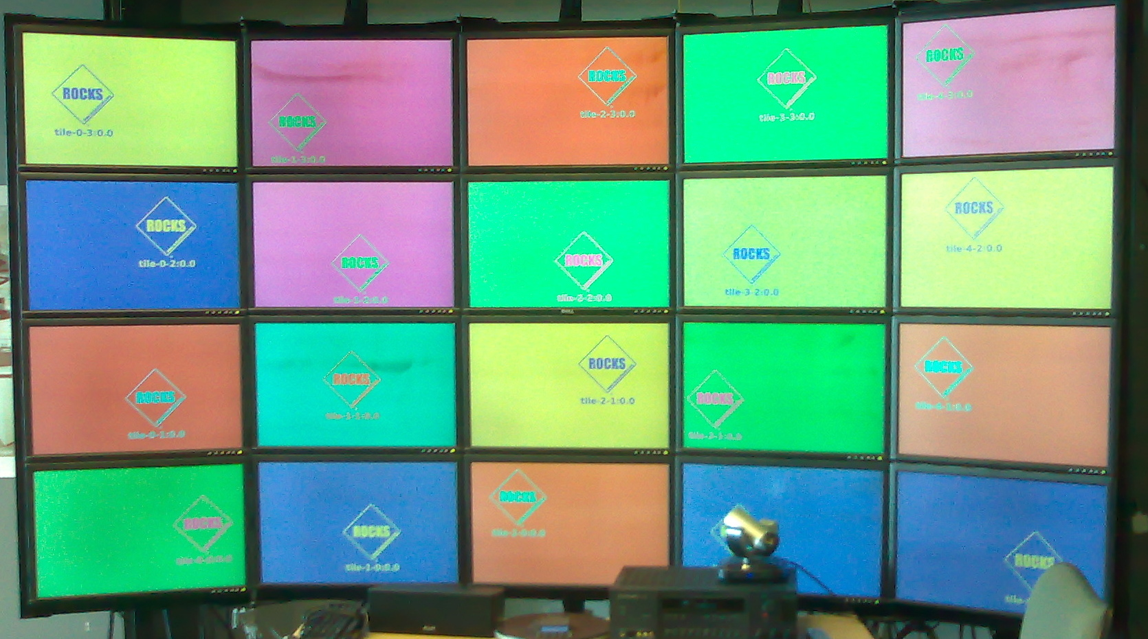
This will generate xorg.conf files for each tile node, copy them to the tile nodes, and restart the X11 server. Once the Tile nodes restart X11 your wall should look like the following picture. Note that each display is labeled according the connected Tile node.
Completed installation for a standard visualization wall.
TwinView support is when a single nVidia card can support two displays, that is, one tile node drives two displays. This section describes how you configure your viz cluster when your Tile nodes are in TwinView mode. For details on the XML syntax please see the above section. The difference in the TwinView configuration is each Tile node is listed in twice in the XML.
 | When connecting a single video card to two display you must connect the primary video connector to the LCD above (or to the left) of the secondary connector. |
This simplest method to create you layout XML is to start from scratch rather than modifying the defaults as is documented in the non-twinview section above.
Here is the relevant portion of /tmp/tilelayout.xml:
<wall> <defaults card="1" hres="1920" vres="1200" hborder="80" vborder="80"/> <col> <display host="tile-0-0"/> <display host="tile-0-1"/> <display host="tile-0-2"/> </col> <col> <display host="tile-0-0"/> <display host="tile-0-1"/> <display host="tile-0-2"/> </col> <col> <display host="tile-1-0"/> <display host="tile-1-1"/> <display host="tile-1-2"/> </col> <col> <display host="tile-1-0"/> <display host="tile-1-1"/> <display host="tile-1-2"/> </col> <col> <display host="tile-2-0"/> <display host="tile-2-1"/> <display host="tile-2-2"/> </col> </wall> |
After you update your tilelayout XML, now apply it to the database:
# rocks create viz layout /tmp/tilelayout.xml |
Finally, reconfigure your tiles:
# rocks sync viz |
This will generate xorg.conf files for each tile node, copy them to the tile nodes, then restart the X11 server. Once the Tile nodes restart X11 your wall should look like the following picture. Note that each display is labeled according the connected Tile node.
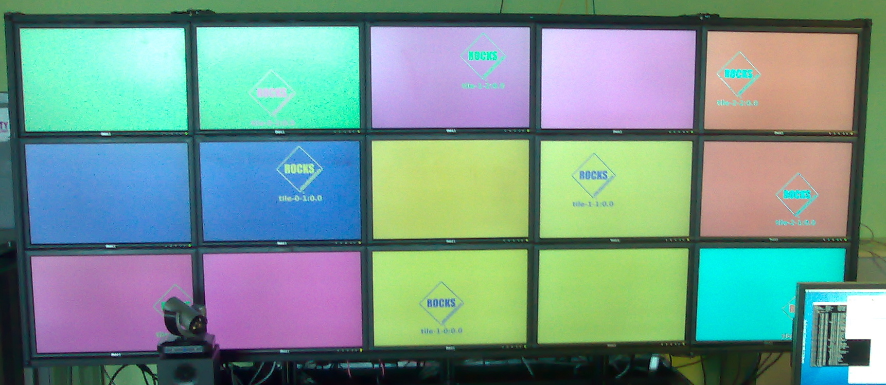
Completed installation for a TwinView visualization wall.