USB Client Driver Technology
This topic describes the technology that the USB Client Driver provides.
USB
The Universal Serial Bus (USB) is a high speed data transport mechanism that uses a 4 wire cable attached to a USB Host to transfer signals and bus power to low cost peripherals (clients). Theoretically, up to 127 devices (such as keyboards, video cameras etc.) can share the bus, although less than four devices is more typical.
There are two versions of the USB standard in use: V1.1 and V2.0. The following table shows the speeds supported by the different versions:
USB Speeds
Name |
Rate |
USB Version |
High Speed |
480Mbit/s |
2.0 only |
Low Speed |
12Mbits/s |
1.1 and 2.0 |
Full Speed |
1.5Mbits/s |
1.1 and 2.0 |
As the table shows USB V2.0 adds support for the higher speed of 480Mbit/s.
The USB system consists of single USB host controller (the USB Host) connected to a number of USB peripheral devices. The host is the bus master, initiating all transactions over the bus.
A client device is a USB peripheral device. It is connected to a USB Controller and responds to transactions addressed to it from the Controller. The Universal Serial Bus Specification 1.1 describes how a USB Host sends commands to a peripheral and how data can be transferred from and to a Client. The main points are:
USB is a Host polled bus. This means that a peripheral cannot send a data packet unless the Host has requested it. The request must either be accepted, and the data packet sent within a given time period, or refused.
Every peripheral attached to the USB is allocated a unique device address. The Host uses the device address to direct its communication to a particular device. In fact, the Host sees the peripheral as a collection of endpoints. Each endpoint is an address within the peripheral to which the Host sends packets or from which the Host receives packets.
Endpoints are grouped together by the peripheral into Interfaces. The Host regards each peripheral as a set of functions and communicates with each function via its Interface. Simple devices, such as mice, contain only one function, other devices may contain more than one function, e.g. a monitor may contain speakers and a microphone.
Each function requires its own driver at the Host end which communicates with the function within the peripheral using a USB class driver or vendor defined protocol. The function informs the Host what protocol it understands via its Interface.
The USB Client Driver supports:
multiple USB interfaces, i.e. it supports licensee products that implement multiple USB interfaces simultaneously
alternate USB interfaces
a single USB Configuration only; the API does not provide a mechanism for specifying more than one USB configuration.
extended standard endpoint descriptors.
reading and modifying standard descriptors.
setting class specific interface and endpoint descriptors.
remote wakeup signalling.
reading device directed Ep0 (Endpoint Zero) traffic.
Endpoint types
There are four endpoint types corresponding to the four transfer types:
Control endpoints
These are serially bi-directional. This means that they can send and receive data, but not simultaneously.
Every peripheral has at least one control endpoint. Although other control endpoints are possible, Symbian platform only allows Endpoint zero (Ep0) as the control endpoint. Ep0 is a shared resource, which must always be available.
Ep0 is vital for the operation of the device. Its primary function is the control endpoint for the Host. When the device is first connected to the Host, a process known as enumeration must occur, and this takes place through Ep0. During enumeration, the client tells the Host what kind of device it is and what classes it supports. Enumeration is complete, for the purpose of writing client drivers, when the Host moves the client into its configured state. The Host moves the client into its configured state when a Host driver is available to communicate with the client.
Ep0 needs handling with some sensitivity. Every request arriving on Ep0 must be handled either by the Controller or by a client class driver. Each request must be moved through the data phase, even if there is no associated request data, so that the status phase may begin. It is imperative that this happens otherwise endpoint zero will be unable to accept any further requests. This could result in the Host stopping communication with the device.
Bulk endpoints
These are unidirectional. They can have the IN or the OUT direction.
The IN direction means sending packets to the Host. The OUT direction means receiving packets from the Host.
Bulk endpoints can supply a maximum of 64 bytes of data per packet, but such transfers have no guaranteed bus bandwidth.
Interrupt endpoints
Interrupt endpoints are similar to Bulk endpoints but, in addition, the endpoint descriptor specifies how often the Host should poll the endpoint for data. The polling frequency may be anything from 1ms to 255ms.
Isochronous endpoints
Isochronous endpoints can deliver up to 1023 bytes of data per packet, but there is no retry capability if an error is detected. Like Interrupt endpoints, they have an associated polling frequency, which is fixed at 1ms.
Endpoint numbering
Two numbering schemes are used within the USB implementation. There is also the external USB address numbering scheme.
Applications or class drivers use virtual endpoints when communicating with the USB client driver. These numbers are used when exchanging data over the USB.
Virtual endpoints range in value from 1 to KMaxEndpointsPerClient, and applications refer to these endpoints by number when using the user side handle to the USB client driver.
For applications that implement a specific USB device class, and which need access to endpoint-0, virtual endpoint-0 is available. This endpoint is special because it does not belong to any specific interface. It is always available and, at the interface to the USB client driver, is the only bi-directional endpoint.
Implementation note
Within the platform independent layer, virtual endpoint numbers are represented by instances of the internal class TUsbcLogicalEndpoint. Note that there is no representation for virtual endpoint-0.
Physical endpoints
Physical (or 'real') endpoints are used at the interface between the platform independent layer and the platform specific layer within the USB client controller. They represent endpoints physically present on a given device.
Implementation note
Within the platform independent layer, physical endpoint numbers are represented by instances of the internal class TUsbcPhysicalEndpoint, in the array represented by the internal data member DUsbClientController::iRealEndPoints.
To simplify array indexing, the numbering scheme uses "transformed" USB endpoint addresses. We represent each channel as a separate endpoint, RX (OUT) channel as iRealEndpoints[n] and TX (IN) channel as iRealEndpoints[n + 1].
The two layers of the USB client controller, i.e. the Platform Independent layer and the Platform Specific layer, use a numbering system known as canonical endpoint numbers when communicating between each other. The physical endpoint numbers are never used explicitly.
This system is based upon the physical endpoint number, but takes the direction of the endpoint into account. If r is the physical endpoint number, then the corresponding canonical endpoint number is a value defined as:
This means that canonical endpoint numbers fall into a range from 0 to 31.
For example, Endpoint 0 (Ep0) is represented by 2 canonical endpoint numbers:
Converting between Endpoint number representations
It is possible to convert between the Endpoint Address representation and the Canonical Endpoint. The following text explains how these values are stored in memory and shows the conversion process:
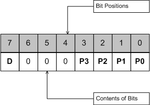
Endpoint Address
where the numbers 0-7 represent bits 0-7 of the byte containing the endpoint address.
D = Direction: 0 = Receive/IN, 1 = Transmit/OUT
P3 P2 P1 P0 represents the physical endpoint number (0-15)
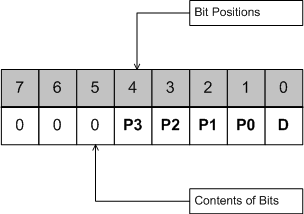
Canonical Endpoint Number
The canonical endpoint number is just the endpoint address rotated left by 1 bit as shown below:
Summary of Endpoint Number Representations
The APIs use the following conventions for representing endpoint numbers types: