| Inkscape » Quick Start » The Northern Pacific Railway Logo - A Tracing Example |    |
|---|
| Inkscape » Quick Start » The Northern Pacific Railway Logo - A Tracing Example | |
|---|
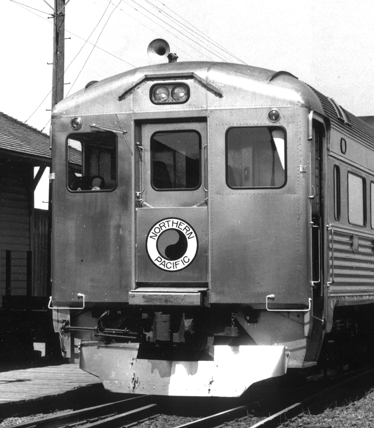
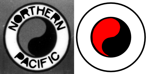
Inkscape's auto-tracing capability is very useful for turning existing artwork into SVG drawings. In this example, we will create the artwork for a logo from a photograph. The logo is for the Northern Pacific (or NP) railroad, which features the Yin and Yang symbol. This tutorial will cover use of the Trace Bitmap dialog as well as manipulation of paths. The use of Layers is also introduced.

The steps are:
Start Inkscape and setting the drawing size.
Import the source photo.
Auto trace the logo.
Clean up the logo paths.
Procedure 1.4. Creating the Northern Pacific Logo
Set up the drawing.
To begin, start Inkscape.
Follow the instructions for setting the page size and grid spacing given in the Swedish flag example but set drawing size to a width of 500 and a height of 500 pixels. Do not turn on the Grid.
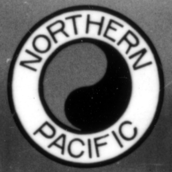
You can use any photograph (in PNG, GIF, or JPEG form) with a logo for this exercise. However, sharp, high resolution photographs work best. I will use part of a photograph from the railroad photographer James M. Fredrickson. The photograph has been cropped to show only the logo. If you wish to use the same photograph as used in the exercise, you can download it from the book's website: http://tavmjong.free.fr/INKSCAPE/.
Import the photograph.
Import the photograph using the →
![]() Import...
(Ctrl+I) dialog.
Import...
(Ctrl+I) dialog.
Adjust the size and position of the photograph.
Adjust the photograph's size and position to match the Inkscape page with the
Select Tool
![]() (keyboard shortcut
F1).
Drag the corners while holding down the Ctrl
key to preserve the aspect ratio. Drag the body to translate the
photo.
(keyboard shortcut
F1).
Drag the corners while holding down the Ctrl
key to preserve the aspect ratio. Drag the body to translate the
photo.
Trace the logo.
Inkscape utilizes the potrace tracing
library to create SVG paths from
bitmap images. To trace the picture, call up the
Trace Bitmap dialog
( →
![]() Trace Bitmap...
(Shift+Alt+B)).
Trace Bitmap...
(Shift+Alt+B)).
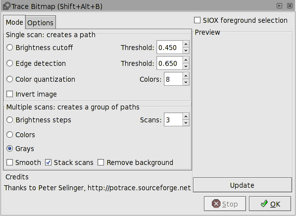
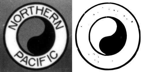
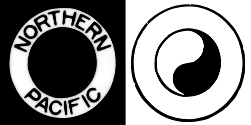
The Trace Bitmap dialog presents a number of choices for how the tracing is done. Looking at the image, we see that there are three different grayscale levels. This suggests that we use one of the Multiple scans methods. As this is a monochrome photograph, we'll try the Grays option with Scans set to three. This will give us three regions, each corresponding to one of the grayscale levels. There is the possibility to smooth the bitmap prior to tracing by checking the Smooth box. This is not necessary as our starting photograph doesn't have any speckle. Finally, there is an option to generate paths for mutually exclusive areas or that include all darker regions. The latter is more useful for us, so we check the Stack scans option box. The resulting traces are shown below.

The paths generated with the Grays option are usable as a starting point for the NP logo. However, we might be able to do better if we use the Single scan - Brightness cutoff method, optimizing the threshold for each scan.
Select the Image Brightness option in the Trace Bitmap dialog. Adjust the Threshold to create a well-defined Yin and Yang path. Pressing the Update button will create a preview. A threshold of 0.15 seems to work well. After finding a good value, click on the OK button to generate the path.
Updated for v0.45.
The scan has many “blobs” that clutter the picture. We could remove these by hand, but there is an easier way. Select the Options tab in the Trace Bitmap dialog. The Suppress speckles option allows the automatic suppression of paths smaller than the specified size. Make sure the Suppress speckles box is checked and set the Size to 50. While your at it, make sure the Smooth corners and Optimize paths boxes are checked. This will result in a smooth scan with fewer nodes. Rescan and the “blobs” should be gone.
It will be easier to edit the traces separately. To do so, we'll
temporarily move the path. This requires a precise move which can
be done with the
Transform dialog
( →
![]() Transform...
(Shift+Ctrl+M)).
Bring up the dialog and select the Move
tab. Move the path a page width to the right by setting the
Horizontal entry to 500 pixels, setting the
Vertical entry to 0 pixels, selecting the
Relative move option, and then clicking on
the Apply button. (One could also move the
path using the
Shift+Arrow
keys to move the path 20 pixels at a time. This may be faster
than calling up the Transform dialog but there is a small risk
of making a mistake in the shifts.)
Transform...
(Shift+Ctrl+M)).
Bring up the dialog and select the Move
tab. Move the path a page width to the right by setting the
Horizontal entry to 500 pixels, setting the
Vertical entry to 0 pixels, selecting the
Relative move option, and then clicking on
the Apply button. (One could also move the
path using the
Shift+Arrow
keys to move the path 20 pixels at a time. This may be faster
than calling up the Transform dialog but there is a small risk
of making a mistake in the shifts.)
Next, repeat the trace with a new threshold. This time optimize the threshold for the lettering. A threshold of 0.65 looks good. Execute the trace. The following figures shows what you should see.
Clean up the traces.
Move the photograph to a different layer.
Objects in Inkscape can be selected by clicking on them. This leads to a small problem when using a rubber-band selection technique where one click-drags to select multiple objects as we will want to do a few times. If the click-drag begins over the photograph, the photograph will be moved. One can avoid this by holding the Shift key down while starting the click-drag, but this is a bit of a pain to do every time. One could lock the picture in place by checking the Lock box in the Object Properties dialog but this isn't recommended. It is non-trivial to select and unlock a locked object.
The preferred solution is to put the picture on a separate Layer. Layers can be thought of as separate drawings on transparent sheets that are stacked on top of each other. The final drawing is what one sees through the stack. In Inkscape, the Layers can be easily locked and unlocked against modification. They can also be made invisible. We'll put the photograph on a locked Layer by itself. Then there is no chance of it moving while we work on cleaning up the tracings.
First, create a new Layer for the photograph. This is done
through the
Add Layer dialog
( →
![]() Add Layer...
).
Enter the name
“Photograph” and hit the Enter key or click on
the Add button. The new layer is created
above the old layer. It is selected automatically. The layer
name is shown in the Status Bar.
Add Layer...
).
Enter the name
“Photograph” and hit the Enter key or click on
the Add button. The new layer is created
above the old layer. It is selected automatically. The layer
name is shown in the Status Bar.
Select the photograph by clicking on an opening in the
tracing (check the Notification Region to
see what is selected). Note that the layer is automatically
changed back to the original layer ("Layer 1") when the
photograph is selected. Move the photograph to the new layer
by using the command
→
![]() Move Selection to Layer Above
(Shift+Page Up). The tracing is
no longer visible. This is because the photograph has been moved
to a layer that is above the layer with the tracing.
Move Selection to Layer Above
(Shift+Page Up). The tracing is
no longer visible. This is because the photograph has been moved
to a layer that is above the layer with the tracing.
Select the “Photograph” layer through the pull-down menu that pops
up when you click on the layer name in the Status Bar.
Lock this layer by clicking on the
![]() icon next to the layer name. The icon should
change to the locked state
icon next to the layer name. The icon should
change to the locked state
![]() . The photograph can now not be moved.
. The photograph can now not be moved.
Finally, move the “Photograph” layer beneath the original layer
by using the command
→
![]() Lower Layer
(Shift+Ctrl+Page Down).
Lower Layer
(Shift+Ctrl+Page Down).
Clean up the Yin and Yang.
Select the path for the circles and the Yin and Yang. The
original layer will be selected. Zoom in the paths by hitting
the 3 key. Each trace creates one path. Each
path is made up of many sub-paths. It is generally easier to
clean up a tracing by converting the sub-paths into independent
paths. Do this by using the →
![]() Break Apart
(Shift+Ctrl+K) command.
Break Apart
(Shift+Ctrl+K) command.
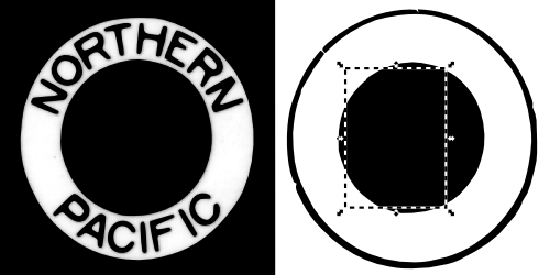
The first thing you will notice is that the Yin and Yang symbol becomes all black. Don't panic! This is because the Yin and Yang has been broken into two pieces, one for the outer circle and one for the Yin shape. Each path takes on the attributes of the prior combined path and thus both have black Fill. Select the Yang (left side) path by clicking inside the area of the Yang path (look at the original photo). You can tell you've selected the correct path by the shape of the bounding box that is shown when the path is selected. If you got the wrong path, try again moving the cursor a bit. It may be necessary to hold down the Alt key while clicking. This will cycle through selecting each object under the cursor in turn. (If the cycling doesn't work, your window manager may be stealing the Alt key. See the section called “Alternative Alt Key” in Chapter 20, Customization, for ways to work around this problem.)
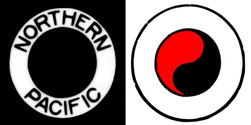
While the photograph is in black and white, the Yang part of the monad in
the NP logo should be red. Set the Fill color of the
path red using the
Fill and Stroke dialog
( →
![]() Fill and Stroke...
(Shift+Ctrl+F)).
Fill and Stroke...
(Shift+Ctrl+F)).
Clean up circles.
Next we will replace the complicated path for the outer circle
with... you guessed it, a circle. Select the Ellipse Tool
![]() from the Tool Controls. To create a circle, hold
down the Ctrl key while click-dragging the
mouse from one corner of a imaginary box (the bounding box) that
encloses the outer circle, to the opposite corner of the
imaginary box. Don't worry about getting the size and position
correct at this point.
from the Tool Controls. To create a circle, hold
down the Ctrl key while click-dragging the
mouse from one corner of a imaginary box (the bounding box) that
encloses the outer circle, to the opposite corner of the
imaginary box. Don't worry about getting the size and position
correct at this point.
Using the Fill and Stroke dialog, turn off the Fill and turn on the Stroke. It is easier to adjust the circle if the circle is semi-transparent and of a different color than the original circle so set the Master Opacity to 50% and the Stroke color to red.
Now we are ready to adjust the circle. Set the stroke width to match the width of the original circle (Width under the Stroke style tab). Next, adjust the size of the circle by dragging either of the two square handles (on left and top of circle). The handles are visible (by default) when any of the shape tools or the Node Tool is selected. Hold down the Ctrl down while dragging to preserve the circle shape. Tapping the Space bar will change to the Select Tool for repositioning the circle. Fine adjustments to the position can be made by holding the Alt key down while using the arrow keys. Tapping the Space bar a second time will reselect the Ellipse Tool.

By this time, you will have realized that the original outer circle is not a true circle. This is because the logo in the photograph is at an angle with respect to the plane of the photograph so the original circle is distorted. We will keep the true circle for the logo but keep in mind that we may need to make other corrections.
The final steps for the outer circle are to delete the original circle and change the stroke of the new circle to a solid black.
The inner solid black circle can also be replaced following the
same steps as for replacing the outer circle with two minor
changes: 1. Use a filled circle without a stroke. 2. Place the
new circle behind the Yang object with the
→
![]() Lower
(Page Down)
command (also available from the Select Tool-Tool Controls).
Lower
(Page Down)
command (also available from the Select Tool-Tool Controls).
Clean up the lettering.
It is now time to clean up the letters. Again we must break up the path into pieces. After doing so, you'll see one big black square. I don't have to remind you not to panic, do I? Select the square and delete it; you should now see a big black circle. Delete that too (select it by clicking its edge). You should now see letters. While we are at it, delete the center black circle leaving only the letters.
Notice that the A, O, and R's are missing their
holes. (You are not panicking, right?) This is because they are
each composed of two paths that need to be put back together. We
can do this for each of the letters, but in this case it is more
convenient to select all the letter paths and merge them into
one path using the →
![]() Combine
(Ctrl+K) command.
Combine
(Ctrl+K) command.
Final steps.
It is time to rejoin the Yin and Yang as well as the circles with the text. Select the Yin and Yang, and the circles and use the Transform dialog to move them -500 pixels in the horizontal direction.
One can now see that the lettering isn't quite spaced correctly. This is again due to the orientation of the logo in the original picture. The lettering needs to be widened a little bit. Select the lettering path and scale it by 3% in the horizontal direction using the Scale tab of the Transform dialog.
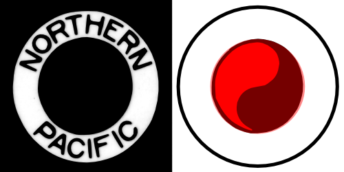
The logo is now finished. You can either delete or hide the original photograph. You can also make fine adjustments to the Yin path with the Node Tool if desired. Save your work as in the previous tutorials.
| |  | |
| A Hiking Club Logo - An Exercise in Paths |  | A Box for Cards - An Isometric Projection |
© 2005-2008 Tavmjong Bah. | Get the book. |