| Inkscape » Attributes » Fill and Stroke Paint |    |
|---|
| Inkscape » Attributes » Fill and Stroke Paint | |
|---|
There are a number of different options for the Fill and Stroke paint of an object. Examples of the different options are shown below. The use of these options for the Fill and the Stroke paint is basically the same, so we'll use the word fill to talk about both at the same time.

The fill type can be set using the Fill and Stroke dialog under the Fill and Stroke paint tabs. The fill type can be one of the following choices (set by clicking an icon):
![]() No paint (transparent).
No paint (transparent).
![]() Flat (solid) color.
Flat (solid) color.
![]() Linear Gradient (a smooth transition between two or more colors).
Linear Gradient (a smooth transition between two or more colors).
![]() Radial Gradient (a smooth transition between two or more colors in a radial direction).
Radial Gradient (a smooth transition between two or more colors in a radial direction).
![]() Pattern (filled with a repeating pattern).
Pattern (filled with a repeating pattern).
![]() Unset (necessary for giving different attributes to cloned copies of an object).
Unset (necessary for giving different attributes to cloned copies of an object).
A Gradient fill type can also be selected by using the Gradient Tool.
Each of the options (except the No paint and Unset options) is discussed below.
Color can be the simplest or the most complicated aspect of a drawing depending on your needs. Color is stored internally in Inkscape as a six-digit hexadecimal number consisting of three pairs of digits. Each pair of digits corresponds to the amount of Red, Green, Blue (RGB). This matches the SVG specification for describing color. For example, a color defined as #FF7F00 has red, blue, and green components of 100%, 50%, and 0%, respectively, of the maximum values.
In some cases, a fourth pair of digits is added to describe Alpha (RGBA). The A or Alpha attribute may not be familiar to many people. This attribute specifies how transparent the fill should be. It can range from 0 for complete transparency to 255 (hexadecimal FF) for complete opacity. The term opacity is often used in place of Alpha. Its value ranges from 0% (0.0) for a transparent object to 100% (1.0) for an opaque object.
Modified in v0.46 (CMS interface):
In principle, this is a simple description for specifying any color. The complexity comes from assuring that the color reproduced on a display or in printing matches the color the artist envisioned. Various color “systems” have been developed to facilitate this. Inkscape supports base ICC profile functionality through the use of LittleCMS. Setting up color management can be done under the Color management section in the Inkscape Preferences dialog. Color managements support is only available under Linux and Macintosh OS X. Profiles internal to a bitmap are also not handled. A complete discussion of this topic is beyond the scope of this book.
The fill color of an object can be modified a variety of ways including using the Fill and Stroke dialog, the Palette, the Swatches dialog, and the Dropper Tool. Some of these methods can also be used to change the color of a Gradient stop when a Gradient handle is selected.
When the use of a flat (or solid) color is specified for the Fill and Stroke paint of an object, the corresponding tab of the Fill and Stroke dialog will show five sub-tabs, each one corresponding to a different method of specifying the color plus one for color management. Each method is described next in its own section.
Except for the Wheel tab, each color parameter can be set by either dragging a slider (small triangles), typing the desired value into the entry box, using the up/down arrows in the widget (Right Mouse+Click on an arrow causes the value to change to the minimum or maximum, Middle Mouse+Click cause the value to increment or decrement by 10), or the Up/Down Arrow keys after the entry box is selected. The slider bar shows the current value (triangles) and what the color will look like as that slider is dragged.

The A or Alpha attribute specifies how transparent the fill should be, 0 for completely transparent and 255 (100) for completely opaque in the case of the RGB, HSL, and Wheel (CMYK) methods.
RGB (Red, Green, Blue) is a method for specifying a color in terms of the three additive primary colors. This is the native method for computer screens. Range of allowed values is from 0 to 255 (0 to FF in hexadecimal).

HSL (Hue, Saturation, Lightness) is a method for specifying color in terms of hue (color in optical spectrum), saturation (intensity-purity), and lightness. The range for saturation is from a pure color to gray. The range for lightness is from black to pure color to white. Range of allowed values is from 0 to 255 (0 to FF in hexadecimal).

CMYK (Cyan, Magenta, Yellow, Key [Black]), is a method for specifying color in terms of subtractive primary colors and is commonly used in printing. Range of allowed values is from 0 to 100.
![[Aviso]](../images/admons/warning.png) | Aviso |
|---|---|
Inkscape stores color internally in the RGB format. This is the only color specification supported by SVG. Furthermore, the entry boxes are set up so that the value in one is always zero. (Any color in RGB color space can be defined using only three of the CMYK terms. The definition is not unique.) Better support for CMYK is planned. |

The Wheel is an alternative way of changing color in the HSL paradigm. Dragging the line around the circle changes the Hue. Dragging the small circle within the triangle parallel to the edge that varies from white to black changes the Lightness and dragging perpendicular to that edge changes the Saturation.

The color Palette, located near the bottom of the main
Inkscape window, and the Swatches dialog
( →
![]() Swatches...
(Mayús.+Ctrl+W)) allows one to quickly set the color of an
object's Fill or Stroke or to set the color of a
Gradient Stop. They can also be used to set the
Current style. There use is essentially identical so they will
be treated together. The visibility of the Palette can be
toggled via a check box in the → submenu.
Swatches...
(Mayús.+Ctrl+W)) allows one to quickly set the color of an
object's Fill or Stroke or to set the color of a
Gradient Stop. They can also be used to set the
Current style. There use is essentially identical so they will
be treated together. The visibility of the Palette can be
toggled via a check box in the → submenu.

The following methods are available for both the Palette and the Swatches dialog:
You can also drag colors to or from other applications that support Drag and Drop.
Inkscape has a variety of built-in palettes (some
copied from Gimp).
More palettes can be added by installing palette
files in the directory share/palettes. The
files use the Gimp palette file structure where colors are
defined in terms of a triplet of numbers in a "RGB"
format. See “Custom Swatches or Palettes” in Capítulo 20, Customization, for details.
Both the Palette and the Swatches dialog have a pull-down menu (far right) where you can set the size and shape of the swatches, if the colors should be displayed in one row or in multiple rows, and which palette should be used. Hovering the pointer over a swatch will display a color's name in a tool tip. A scroll bar gives access to colors in a palette that are not displayed when there are too many colors to fit.
The Style Indicator located on the left side of the Status Bar displays information on selected objects, text fragments, or Gradient stops. The indicator includes a number of methods to alter style including: pop-up menus, targets for Drag and Drop colors, and Color Gestures.
The Style Indicator has three parts showing Fill, Stroke paint, and opacity (O), which show attributes for selected objects or text fragments. The Fill and Stroke paint parts are referred to as the fill indicators.

A displayed fill attribute can be one of:
Color swatch: Shows color with (left) and without (right) Alpha (Alpha refers to the Fill and Stroke paint attributes and not the object's Master opacity).
N/A: Not Applicable (i.e., no object selected).
None: No fill defined.
Unset: fill is unset.
L Gradient: fill is a linear Gradient.
R Gradient: fill is a radial Gradient.
Pattern: fill is a pattern.
Different: More than one object selected with different fill.
When multiple objects are selected and all of the selected objects have a color fill, then one of the following letters will be shown:
m: Selected objects have same fill color.
a: Selected objects have different fill colors. The color displayed is an average of the colors in the selected objects.
For Gradient handles, both parts (Fill and Stroke paint) show the handle color.
The Style Indicator has a number of features that depend on the part.
Fill/Stroke Paint indicators:
A Left Mouse Click opens the Fill and Stroke dialog with the corresponding tab selected.
A Middle Mouse Click on a bar removes the fill from the selected objects if a fill is defined. If no fill is defined, it sets the fill to black.
A Right Mouse Click on a bar opens a pop-up menu as discussed below.
A color from the Palette or Swatches dialog can be dragged and dropped onto one of the fill indicators to change the fill of all selected objects.
Stroke indicator:
A Left Mouse Click opens the Fill and Stroke dialog to the Stroke style tab.
A Right Mouse Click opens the a pop-up menu that allows the stroke width unit to be changed as well as a preset width to be selected. The stroke can also be removed with this menu.
Opacity indicator:
A Right Mouse Click on the numeric field opens up a pop-up menu with preset opacity values.
A Middle Mouse Click on the "O:" label cycles through the opacity values 0%, 50%, and 100% (0.0, 0.5, and 1.0).
A Right Mouse Click on either the Fill or Stroke paint bar opens a pop-up menu with entries that act on the Fill or Stroke paint of the selected objects or text fragments, depending on which bar was clicked. If a Gradient handle is selected, the menu entries apply to that handle.

Edit fill... (Edit stroke...): Opens Fill and Stroke dialog. (The dialog can also be opened directly by a Left Mouse Click on the Fill or Stroke paint part of the Style Indicator.)
Last set color: Applies the last set color to the Fill or Stroke paint of selected objects. A color is set when a color is applied to any object or when a color is selected from the Palette.
Last selected color: Applies the last selected color to selected objects. The last selected color is the color of the previously selected object(s) prior to selecting the object(s) whose color is to be changed. If the color is to be applied to multiple objects, they must be selected together using a rubber-band selection.
Invert: Inverts the color of the Fill or Stroke paint of selected objects. If more than one object is selected, the colors of those objects are averaged before the color is inverted. The opacity is not changed.
White: Set Fill or Stroke paint to white.
Black: Set Fill or Stroke paint to black.
Copy color: Copies color of selected objects to the clipboard in hexadecimal format. If more than one object is selected, the colors of those objects are averaged.
Paste color: Pastes color to selected objects from the clipboard.
Swap fill and stroke: Exchanges Fill and Stroke paint colors.
Make fill (stroke) opaque: Sets Fill or Stroke paint to full opacity. (Does not affect Master opacity.)
Unset fill (stroke): Unsets the Fill or Stroke paint of selected objects.
Remove fill (stroke): Removes the Fill or Stroke paint of selected objects.
New in v0.46.
Color Gestures is the name give to changing the color of a Fill, Stroke, or Gradient Stop by dragging the mouse from a fill indicator into the Inkscape window. The principle is that as you drag the mouse, the color will change proportionally to the distance from a 45° line from the indicator. The farther away you are, the more subtle the changes can be. Changes are made in the HSL color space.

With out any modifier key, changes are made to hue. With the Shift changes are made to saturation while with the Ctrl changes are made to lightness. Note that the letter next to the cursor will change to indicate the mode. Key modifiers can be changed while dragging. When a key modifier is changed, the “zero” line (normally at 45°) changes to pass through the current cursor position. This is to avoid abrupt changes in color when changing modifiers. The Alt modifier disables changes to the color so that the cursor can be repositioned.
If more than one object or Gradient Stop is selected, the starting color will be the average color of the selected items and the final color will be the same. If you wish to shift the color in the same way for a number of objects but preserve the relative differences use the Tweak Tool.
Color gestures are very useful once you get the hang of them. It is well worth spending a little time to play with them!
The Fill and Stroke paint color of an object can be changed by using the Dropper Tool to grab an existing color in the drawing. Options allow for grabbing the average color over a circular region, inverting the grabbed color, and saving the grabbed color to the system clipboard (as a RGBA hexadecimal number).
To use the Dropper Tool, first select the object that you want to modify with a tool other than the Dropper Tool. Recall that you can switch temporarily to the Select Tool by using the Space Bar.
Then select the Dropper Tool by clicking on the
![]() icon (F7 or
D) in the Tool Controls. Finally click with the
Dropper Tool on the desired color. The shortcut
D will toggle between the Dropper Tool
and any other tool (as of v0.46).
icon (F7 or
D) in the Tool Controls. Finally click with the
Dropper Tool on the desired color. The shortcut
D will toggle between the Dropper Tool
and any other tool (as of v0.46).
The Shift causes the chosen color to be applied to the object's Stroke paint rather than the Fill. The Alt causes the inverse color to be applied. The Shift and Alt keys can be used in combination. However, neither of the modifier keys are useful when copying a color to the clipboard.
Left Mouse Click: Pick Fill color.
Left Mouse Drag: Pick average Fill color (color is averaged over circle created during drag).
Ctrl+C: Copy color under cursor to system clipboard in the form of an 8-digit hexadecimal number (two digits for each of RGBA).
Changed in v0.45 and again in v0.46:
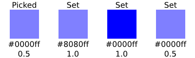
The Dropper Tool Tool Controls has two buttons (check boxes in v0.45) that determine if the Alpha of a color should be picked and/or set. These settings affect the way a color is picked if the “picked” object has an opacity different from 1.0 (or 100%).

Pick alpha disabled: The color picked is as shown on the screen. For example, picking the color from an object with a dark blue fill but an opacity of 0.5 would result in a light blue color with an opacity of 1.0. Opacity of set object not changed.
Pick alpha enabled, Set alpha disabled: The color picked is the color that the object would have if its opacity was 1.0. A dark blue object with an opacity of 0.5 would result in a dark blue color (an opacity of 1.0). Opacity of set object not changed.
Pick alpha enabled, Set alpha enabled: The color and opacity are both copied from the picked object. A dark blue object with an opacity of 0.5 would result in a light blue color composed of a dark blue fill with an opacity of 0.5. Opacity of set object changed. Note: This is only applicable if the color is picked from an object with transparency that is not over another object.
Note: v0.45 has a bug. If the color is not picked correctly with a Left Mouse Click, use a small Left Mouse Drag.
Onscreen creation and editing of intermediate Stops added in v0.46.
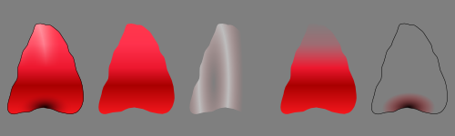
Gradients are a smooth blending from one color to another. Gradients can be used to build up complex shading of an object as shown in the flower petal below. Note: As of v0.45, Inkscape supports the Gaussian Blur filter, which may be an easier way to produce complex shadings.
In Inkscape, Gradients can be linear or radial and can consist of transitions between two or more well-defined colors referred to as Stops.

Inkscape does not support non-linear Gradients. Non-linear Gradients can be simulated by adding extra Stops.
There are three parts to using a Gradient; each treated in the next three sections:
The use of linear and radial Gradients is essentially the same and both will be treated together.
![[Nota]](../images/admons/note.png) | Nota |
|---|---|
If you want a Gradient to transform with an object, you must
toggle on this option using the
|
Gradients can be attached to an object either with the Fill and Stroke dialog or through the use of the Gradient Tool.
To attach a Gradient with the Fill and Stroke dialog, simply
select an object and click on either the linear
![]() or radial Gradient
or radial Gradient
![]() icons
in the dialog. A Gradient with two Stops will automatically
by created and applied to the object. The Stops will have the
color of the previous Fill with one Stop having full opacity
and the other full transparency.
The following figure shows the dialog after attaching a Gradient
this way.
icons
in the dialog. A Gradient with two Stops will automatically
by created and applied to the object. The Stops will have the
color of the previous Fill with one Stop having full opacity
and the other full transparency.
The following figure shows the dialog after attaching a Gradient
this way.

An already defined Gradient can be assigned to the object by selecting the Gradient from the drop-down menu under the Fill tab of the Fill and Stroke dialog. A Gradient can also be assigned to the Stroke of an object under the Stroke paint tab.
To attach a Gradient with the Gradient Tool, select
the tool by clicking on the
![]() icon
(Ctrl+F1 or g) in the Tool Box.
icon
(Ctrl+F1 or g) in the Tool Box.
The Gradient Tool Tool Controls has options to choose a linear
![]() or a radial
or a radial
![]() Gradient and the application of the Gradient to the
Fill
Gradient and the application of the Gradient to the
Fill
![]() or Stroke
or Stroke
![]() of an object. Once the options are selected, Left Mouse
Drag across an object to attach a Gradient. The
start and stop point of the drag will define the range of the
Gradient (where the start and end Stops are placed,
see below).
If an already defined Gradient has been chosen from the
drop-down menu in the Tool Controls it will be applied to the
object. Otherwise a two Stop Gradient will
automatically be created with both Stops the color of the
objects existing Fill and with one Stop full opacity
and the other with full transparency.
of an object. Once the options are selected, Left Mouse
Drag across an object to attach a Gradient. The
start and stop point of the drag will define the range of the
Gradient (where the start and end Stops are placed,
see below).
If an already defined Gradient has been chosen from the
drop-down menu in the Tool Controls it will be applied to the
object. Otherwise a two Stop Gradient will
automatically be created with both Stops the color of the
objects existing Fill and with one Stop full opacity
and the other with full transparency.
Gradients can be modified by adding, deleting, moving, or changing the color and opacity of Stops.
As of Inkscape v0.46, Gradients can be edited onscreen. This is much more convenient than using the Gradient Editor dialog.
An object with a Gradient displays Gradient handles when the Gradient Tool, Node Tool, or one of the shape tools is active (the latter two if enabled in the Inkscape Preferences dialog). Some editing actions work when any of these tools is active, others work only with the Gradient Tool.
Circle, diamond, and square handles represent start, intermediate, and end Stops respectively. Editing Stops has many parallels to editing nodes.
Stops can be selected by clicking on them with the Gradient Tool, the Node Tool, or one of the shape tools. To select more than one use Shift+Left Mouse Click. With the Gradient Tool you can use a rubber-band selection by using Shift+Left Mouse Drag or you can select all the Stops by using Ctrl+A.
To add a new intermediate Stop, with the object selected and the Gradient Tool active:
To remove an intermediate Stop, with the Gradient Tool active:
To move an intermediate Stop:
Note: You cannot move a Stop past an adjacent Stop.
There are several ways to see and change the style (color and/or transparency) of one or more Stops. In general, if no Stop is selected, indicators and changes apply to the whole object; if one Stop is selected, indicators and changes apply to that Stop; and if multiple Stops are selected, indicators show an average value for the selected Stops and changes apply to all selected Stops.
There is a dedicated Gradient Editor dialog for editing Gradients. It is envisioned that this dialog be removed as redundant in the future. To call up the dialog, click on the Edit... button, either in the Fill and Stroke dialog or the Gradient Tool-Tool Controls. Note that which Gradient is being edited does not change automatically when you select an object with a different Gradient.
In this dialog, the Gradient is shown at the very top. Next down is the current Stop. You can see that the Stop shown above (stop2387) is a solid blue, fully opaque with Alpha = 255. You can also see from the Offset slider that the Stop shown is set all the way to the left (and as the Stop is at one limit of the Gradient, its position can't be moved). The color and transparency of this Stop can be changed in the Stop Color section. The tabs work the same as those described in the Flat Colors section above. The Dropper Tool can also be used to change one of the end Gradient colors by first selecting the corresponding Gradient handle. (To modify a non-end Gradient color, copy the color to the clipboard by using Ctrl+C with the desired color selected with the Dropper Tool and then paste into the Gradient Editor RGBA entry box.)
To edit another Stop, select that Stop in the pull-down menu. In the default case described above, the second Stop (stop2389) has the same color as the first but is fully transparent (e.g., Alpha = 0). This is shown in the current Stop section by the divided box. The left half shows the color with Alpha and the right half without Alpha. Note also that the Offset slider is fully to the right.

To add a Stop, click on the Add stop button. The new Stop will be added to the right of whichever Stop was selected, unless that Stop was the farthest to the right, in which case the new Stop will be added to the left. The position, color, and transparency for the new Stop will be set to halfway between its neighbors.
The following figures show a third Stop added to a Gradient after its color and position have been adjusted.


To delete a Stop, select the Stop, then click on the Delete stop button. As at least two Stops are required to define a Gradient, you cannot delete a Stop if only two are defined.
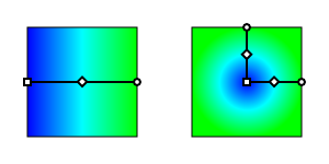
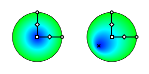
Once a Gradient has been applied to an object, the orientation and extent of the Gradient can be changed via dragging the outer two Gradient Stops indicated by the square and circle handles. The handles appear when the Gradient Tool is selected. They will also appear by default when many of the other tools are selected (controlled by the Enable Gradient editing option in the Inkscape Preferences dialog under each tool tab). For linear Gradients, one set of handles define the range of the Gradient. The Gradient is parallel to the line connecting the two handles. For radial Gradients, there are two sets of handles (or Stops) at right angles to each other, sharing the square center handle. The center, handle controls the origin of the Gradient (one “edge”), while the two circular handles control the range of the Gradient in orthogonal directions. This allows a radial Gradient to have an elliptical shape.

A radial Gradient can be made asymmetric by dragging the center handle (diamond) while holding down the Shift key. A cross will appear where the center of the Gradient is located. The cross can be dragged to make further adjustments.
Gradient handles from two different objects will snap together if one is placed over the other. This facilitates aligning Gradients between different objects. The handles will then move together. If multiple objects are selected when a Gradient is created, all the objects will share a common Gradient.

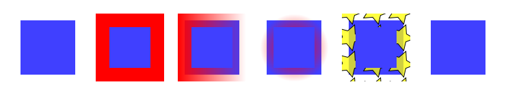
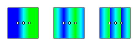
An option only accessible through the Gradient tabs of the Fill and Stroke dialog is defining how the area outside the Gradient range is filled. The three options are: fill with the solid color of the edge Stops (None), fill with a reflection of the same Gradient (Reflect), and fill with a translation of the same Gradient (Direct). The effect of these three options is shown next.

The keyboard shortcut Shift+R reverses the Gradient direction when the Gradient Tool is active. This is especially useful for radial Gradients where one cannot just drag the Gradient handles to reverse the Gradient.
Updated for v0.46.
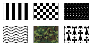
Any object or set of objects can be turned into a Pattern and used in the fill of an object. The Pattern can be shifted, rotated, and stretched as necessary. Inkscape, as of v04.6, includes a set of Patterns accessible through the Fill and Stroke dialog. The Vine Design tutorial covers creating and using Patterns.
| Aviso |
|---|---|
Check the licenses of the bitmap patterns included with Inkscape to see if they are compatible with your artwork. They are not public domain! (Look inside the SVG file or use the XML Editor to look in the “defs” section.) |
The Patterns included with Inkscape are defined in the file
patterns/patterns.svg located in the Inkscape
“share” directory. Edit or replace this file to include
your own stock Patterns.
To use a Pattern, two or three steps are necessary. The first, optional step, is to create a Pattern. The second is to apply the newly created Pattern or an Inkscape provided Pattern to an object. And the third is to adjust the Pattern as necessary.
Patterns are very easy to create. Simply select the object or objects you wish to use as a Pattern and then use the → → (Alt+I) command.
After converting the selection to a Pattern, the original selection is replaced by a Rectangle shape object filled with the new Pattern (and with an invisible stroke). This new object can be deleted but the Pattern will remain. Patterns have a life of their own.
The “tile” size of the Pattern is the total bounding box of the objects in the Pattern. If space is required around the objects, a non-visible rectangle object can be added or the Pattern size can be edited with the XML Editor dialog.
The object(s) in any Pattern can be edited by selecting an object that is filled with that Pattern and then using the → → (Mayús.+Alt+I) command. The original objects will reappear in their original place (built-in Patterns will appear in the upper-left corner). After editing, the objects can be again turned into a Pattern. Both the old and new Patterns are available for use. Other objects filled with the original Pattern remain unchanged. The new Pattern must be “reapplied” to the object the Pattern came from.
To change the fill of an object to a Pattern, simply click
on the Pattern icon (
![]() )
in the Fill and Stroke dialog. Then select the required
Pattern from the pull-down menu. User created Patterns
will be listed first.
)
in the Fill and Stroke dialog. Then select the required
Pattern from the pull-down menu. User created Patterns
will be listed first.

Unfortunately, there is no preview of the Patterns (as with the Gradient tab).
| Nota |
|---|---|
If you want a Pattern to transform with
an object, you must toggle on this option using the
|
| Aviso |
|---|---|
Patterns are not exported to PS and EPS files via the old export routines and are exported incorrectly to PS and PDF files via the Cairo routines (Bug). |
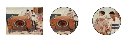
Adjusting Patterns is done by a set of handles. The handles will appear when an object with a Pattern fill is selected and the node or one of the shape tools is active. The handles will appear on the original objects that defined the Pattern, or the former location of those objects if they have been moved or deleted (unless the Pattern has been previously adjusted). In the case of built-on Patterns they will appear in the upper-left corner of the canvas. The following figure shows the location of the handles for a Pattern that has not been adjusted.

To adjust the origin, scale, and orientation of the Pattern, drag the translation handle (×), scale handle (square), and rotation handle (circle). The translation handle can conveniently be dragged over the object with the Pattern fill. Holding the Ctrl key down while dragging will restrict the movement to the horizontal or vertical direction. The scale is governed by the distance between the translation handle and scale handle, the orientation by the relative position of the rotation handle with the translation handle. The following figure shows how the fill changed after the handles have been adjusted.

![[Sugerencia]](../images/admons/tip.png) | Sugerencia |
|---|---|
For SVG viewers that don't support clipping, you can crop a bitmap by turning the bitmap into a Pattern and using it to fill an arbitrary path. |
Inkscape now includes many Patterns that can be used as hatchings. If you need to create a new hatching here is the general procedure. The simplest hatching is to group two rectangular boxes, one with black fill and one with no fill as shown below.

| Aviso |
|---|---|
Inkscape has problems properly displaying Patterns at the Pattern boundaries. Inkscape export to a PNG also has problems. To work around this problem, you can make the Pattern rectangles wider than the maximum width needed to fill an object. Firefox, Opera, and Batik will display patterns without artifacts. Batik can be used for producing a high-quality PNG. |
The Fill Rule dictates what areas are filled when a path overlaps itself or one part of a complex path surrounds another part. The rule applies only to the Fill of an object (and not the Stroke paint). One can choose the Fill Rule from the two choices:
![]() Even-odd.
Even-odd.
![]() Non-zero.
Non-zero.
The difference between these rules is demonstrated in the following figures.
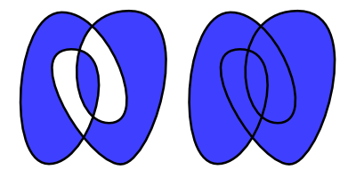
Even-odd rule. In this rule, you start outside the path with the number zero. Every time you cross the object's path, you add one to the number. If the current number is odd, the region is inside the path and therefore colored. If the current number is even, the region is outside the path and is not colored.
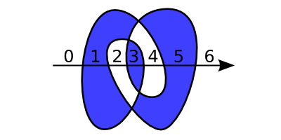
Non-zero rule. In this rule, you start outside the path with the number zero. Every time you cross the object's path with the path going to the left, you add one to the number. If the path is going to the right, you subtract one. If the number is non-zero, the region is inside the path; if it is zero, the region is outside the path.

| |  | |
| Capítulo 9. Attributes |  | Stroke Style |
© 2005-2008 Tavmjong Bah. | Get the book. |

