Licensed to the Apache Software Foundation (ASF) under one or more contributor license agreements. See the NOTICE file distributed with this work for additional information regarding copyright ownership. The ASF licenses this file to you under the Apache License, Version 2.0 (the "License"); you may not use this file except in compliance with the License. You may obtain a copy of the License at
http://www.apache.org/licenses/LICENSE-2.0
Unless required by applicable law or agreed to in writing, software distributed under the License is distributed on an "AS IS" BASIS, WITHOUT WARRANTIES OR CONDITIONS OF ANY KIND, either express or implied. See the License for the specific language governing permissions and limitations under the License.
Apache CloudStack is an effort undergoing incubation at The Apache Software Foundation (ASF).
Incubation is required of all newly accepted projects until a further review indicates that the infrastructure, communications, and decision making process have stabilized in a manner consistent with other successful ASF projects. While incubation status is not necessarily a reflection of the completeness or stability of the code, it does indicate that the project has yet to be fully endorsed by the ASF.
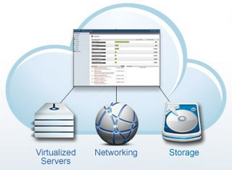
CloudStack is an open source software platform that pools computing resources to build public, private, and hybrid Infrastructure as a Service (IaaS) clouds. CloudStack manages the network, storage, and compute nodes that make up a cloud infrastructure. Use CloudStack to deploy, manage, and configure cloud computing environments.
Typical users are service providers and enterprises. With CloudStack, you can:
Set up an on-demand, elastic cloud computing service. Service providers can sell self service virtual machine instances, storage volumes, and networking configurations over the Internet.
Set up an on-premise private cloud for use by employees. Rather than managing virtual machines in the same way as physical machines, with CloudStack an enterprise can offer self-service virtual machines to users without involving IT departments.
1.2. What Can CloudStack Do?
Multiple Hypervisor Support
CloudStack works with a variety of hypervisors, and a single cloud deployment can contain multiple hypervisor implementations. The current release of CloudStack supports pre-packaged enterprise solutions like Citrix XenServer and VMware vSphere, as well as KVM or Xen running on Ubuntu or CentOS.
Massively Scalable Infrastructure Management
CloudStack can manage tens of thousands of servers installed in multiple geographically distributed datacenters. The centralized management server scales linearly, eliminating the need for intermediate cluster-level management servers. No single component failure can cause cloud-wide outage. Periodic maintenance of the management server can be performed without affecting the functioning of virtual machines running in the cloud.
Automatic Configuration Management
CloudStack automatically configures each guest virtual machine’s networking and storage settings.
CloudStack internally manages a pool of virtual appliances to support the cloud itself. These appliances offer services such as firewalling, routing, DHCP, VPN access, console proxy, storage access, and storage replication. The extensive use of virtual appliances simplifies the installation, configuration, and ongoing management of a cloud deployment.
Graphical User Interface
CloudStack offers an administrator's Web interface, used for provisioning and managing the cloud, as well as an end-user's Web interface, used for running VMs and managing VM templates. The UI can be customized to reflect the desired service provider or enterprise look and feel.
API and Extensibility
CloudStack provides an API that gives programmatic access to all the management features available in the UI. The API is maintained and documented. This API enables the creation of command line tools and new user interfaces to suit particular needs. See the Developer’s Guide and API Reference, both available at Apache CloudStack Guides and Apache CloudStack API Reference respectively.
CloudStack has a number of features to increase the availability of the system. The Management Server itself may be deployed in a multi-node installation where the servers are load balanced. MySQL may be configured to use replication to provide for a manual failover in the event of database loss. For the hosts, CloudStack supports NIC bonding and the use of separate networks for storage as well as iSCSI Multipath.
1.3. Deployment Architecture Overview
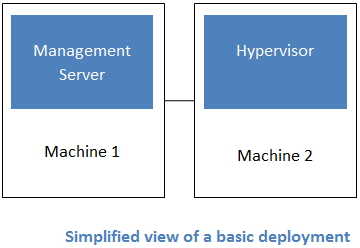
A CloudStack installation consists of two parts: the Management Server and the cloud infrastructure that it manages. When you set up and manage a CloudStack cloud, you provision resources such as hosts, storage devices, and IP addresses into the Management Server, and the Management Server manages those resources.
The minimum production installation consists of one machine running the CloudStack Management Server and another machine to act as the cloud infrastructure (in this case, a very simple infrastructure consisting of one host running hypervisor software). In its smallest deployment, a single machine can act as both the Management Server and the hypervisor host (using the KVM hypervisor).
A more full-featured installation consists of a highly-available multi-node Management Server installation and up to tens of thousands of hosts using any of several advanced networking setups. For information about deployment options, see Choosing a Deployment Architecture.
1.3.1. Management Server Overview
The Management Server is the CloudStack software that manages cloud resources. By interacting with the Management Server through its UI or API, you can configure and manage your cloud infrastructure.
The Management Server runs on a dedicated server or VM. It controls allocation of virtual machines to hosts and assigns storage and IP addresses to the virtual machine instances. The Management Server runs in a Tomcat container and requires a MySQL database for persistence.
The machine must meet the system requirements described in System Requirements.
The Management Server:
Provides the web user interface for the administrator and a reference user interface for end users.
Provides the APIs for CloudStack.
Manages the assignment of guest VMs to particular hosts.
Manages the assignment of public and private IP addresses to particular accounts.
Manages the allocation of storage to guests as virtual disks.
Manages snapshots, templates, and ISO images, possibly replicating them across data centers.
Provides a single point of configuration for the cloud.
1.3.2. Cloud Infrastructure Overview
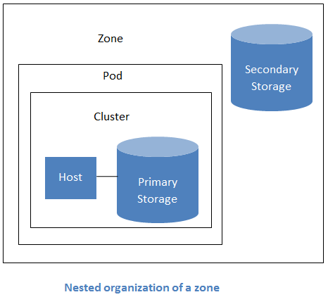
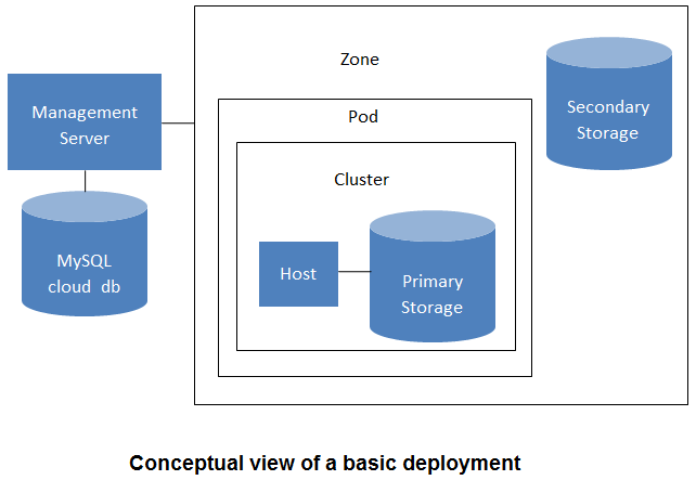
The Management Server manages one or more zones (typically, datacenters) containing host computers where guest virtual machines will run. The cloud infrastructure is organized as follows:
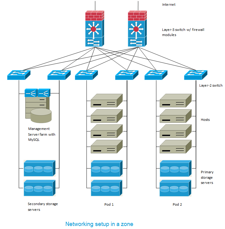
Zone: Typically, a zone is equivalent to a single datacenter. A zone consists of one or more pods and secondary storage.
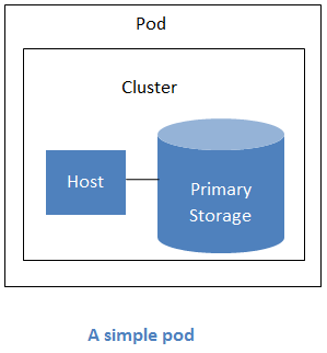
Pod: A pod is usually one rack of hardware that includes a layer-2 switch and one or more clusters.
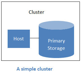
Cluster: A cluster consists of one or more hosts and primary storage.
Host: A single compute node within a cluster. The hosts are where the actual cloud services run in the form of guest virtual machines.
Primary storage is associated with a cluster, and it stores the disk volumes for all the VMs running on hosts in that cluster.
Secondary storage is associated with a zone, and it stores templates, ISO images, and disk volume snapshots.
More Information
For more information, see documentation on cloud infrastructure concepts.
1.3.3. Networking Overview
CloudStack offers two types of networking scenario:
Basic. For AWS-style networking. Provides a single network where guest isolation can be provided through layer-3 means such as security groups (IP address source filtering).
Advanced. For more sophisticated network topologies. This network model provides the most flexibility in defining guest networks.
A zone is the largest organizational unit within a CloudStack deployment. A zone typically corresponds to a single datacenter, although it is permissible to have multiple zones in a datacenter. The benefit of organizing infrastructure into zones is to provide physical isolation and redundancy. For example, each zone can have its own power supply and network uplink, and the zones can be widely separated geographically (though this is not required).
A zone consists of:
One or more pods. Each pod contains one or more clusters of hosts and one or more primary storage servers.
Secondary storage, which is shared by all the pods in the zone.
Zones are visible to the end user. When a user starts a guest VM, the user must select a zone for their guest. Users might also be required to copy their private templates to additional zones to enable creation of guest VMs using their templates in those zones.
Zones can be public or private. Public zones are visible to all users. This means that any user may create a guest in that zone. Private zones are reserved for a specific domain. Only users in that domain or its subdomains may create guests in that zone.
Hosts in the same zone are directly accessible to each other without having to go through a firewall. Hosts in different zones can access each other through statically configured VPN tunnels.
For each zone, the administrator must decide the following.
How many pods to place in a zone.
How many clusters to place in each pod.
How many hosts to place in each cluster.
How many primary storage servers to place in each cluster and total capacity for the storage servers.
How much secondary storage to deploy in a zone.
When you add a new zone, you will be prompted to configure the zone’s physical network and add the first pod, cluster, host, primary storage, and secondary storage.
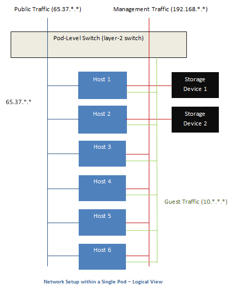
2.2. About Pods
A pod often represents a single rack. Hosts in the same pod are in the same subnet.
A pod is the second-largest organizational unit within a CloudStack deployment. Pods are contained within zones. Each zone can contain one or more pods.
Pods are not visible to the end user.
A pod consists of one or more clusters of hosts and one or more primary storage servers.
2.3. About Clusters
A cluster provides a way to group hosts. To be precise, a cluster is a XenServer server pool, a set of KVM servers, , or a VMware cluster preconfigured in vCenter. The hosts in a cluster all have identical hardware, run the same hypervisor, are on the same subnet, and access the same shared primary storage. Virtual machine instances (VMs) can be live-migrated from one host to another within the same cluster, without interrupting service to the user.
A cluster is the third-largest organizational unit within a CloudStack deployment. Clusters are contained within pods, and pods are contained within zones. Size of the cluster is limited by the underlying hypervisor, although the CloudStack recommends less in most cases; see Best Practices.
A cluster consists of one or more hosts and one or more primary storage servers.
CloudStack allows multiple clusters in a cloud deployment.
Even when local storage is used exclusively, clusters are still required organizationally, even if there is just one host per cluster.
When VMware is used, every VMware cluster is managed by a vCenter server. Administrator must register the vCenter server with CloudStack. There may be multiple vCenter servers per zone. Each vCenter server may manage multiple VMware clusters.
2.4. About Hosts
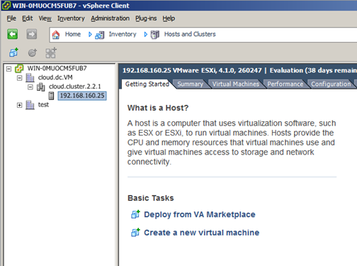
A host is a single computer. Hosts provide the computing resources that run the guest virtual machines. Each host has hypervisor software installed on it to manage the guest VMs. For example, a Linux KVM-enabled server, a Citrix XenServer server, and an ESXi server are hosts.
The host is the smallest organizational unit within a CloudStack deployment. Hosts are contained within clusters, clusters are contained within pods, and pods are contained within zones.
Hosts in a CloudStack deployment:
Provide the CPU, memory, storage, and networking resources needed to host the virtual machines
Interconnect using a high bandwidth TCP/IP network and connect to the Internet
May reside in multiple data centers across different geographic locations
May have different capacities (different CPU speeds, different amounts of RAM, etc.), although the hosts within a cluster must all be homogeneous
Additional hosts can be added at any time to provide more capacity for guest VMs.
CloudStack automatically detects the amount of CPU and memory resources provided by the Hosts.
Hosts are not visible to the end user. An end user cannot determine which host their guest has been assigned to.
For a host to function in CloudStack, you must do the following:
Install hypervisor software on the host
Assign an IP address to the host
Ensure the host is connected to the CloudStack Management Server
2.5. About Primary Storage
Primary storage is associated with a cluster, and it stores the disk volumes for all the VMs running on hosts in that cluster. You can add multiple primary storage servers to a cluster. At least one is required. It is typically located close to the hosts for increased performance.
CloudStack is designed to work with all standards-compliant iSCSI and NFS servers that are supported by the underlying hypervisor, including, for example:
Dell EqualLogic™ for iSCSI
Network Appliances filers for NFS and iSCSI
Scale Computing for NFS
If you intend to use only local disk for your installation, you can skip to Add Secondary Storage.
2.6. About Secondary Storage
Secondary storage is associated with a zone, and it stores the following:
Templates — OS images that can be used to boot VMs and can include additional configuration information, such as installed applications
ISO images — disc images containing data or bootable media for operating systems
Disk volume snapshots — saved copies of VM data which can be used for data recovery or to create new templates
The items in zone-based NFS secondary storage are available to all hosts in the zone. CloudStack manages the allocation of guest virtual disks to particular primary storage devices.
To make items in secondary storage available to all hosts throughout the cloud, you can add OpenStack Object Storage (Swift, swift.openstack.org) in addition to the zone-based NFS secondary storage. When using Swift, you configure Swift storage for the entire CloudStack, then set up NFS secondary storage for each zone as usual. The NFS storage in each zone acts as a staging area through which all templates and other secondary storage data pass before being forwarded to Swift. The Swift storage acts as a cloud-wide resource, making templates and other data available to any zone in the cloud. There is no hierarchy in the Swift storage, just one Swift container per storage object. Any secondary storage in the whole cloud can pull a container from Swift at need. It is not necessary to copy templates and snapshots from one zone to another, as would be required when using zone NFS alone. Everything is available everywhere.
2.7. About Physical Networks
Part of adding a zone is setting up the physical network. One or (in an advanced zone) more physical networks can be associated with each zone. The network corresponds to a NIC on the hypervisor host. Each physical network can carry one or more types of network traffic. The choices of traffic type for each network vary depending on whether you are creating a zone with basic networking or advanced networking.
A physical network is the actual network hardware and wiring in a zone. A zone can have multiple physical networks. An administrator can:
Add/Remove/Update physical networks in a zone
Configure VLANs on the physical network
Configure a name so the network can be recognized by hypervisors
Configure the service providers (firewalls, load balancers, etc.) available on a physical network
Configure the IP addresses trunked to a physical network
Specify what type of traffic is carried on the physical network, as well as other properties like network speed
2.7.1. Configurable Characteristics of Physical Networks
CloudStack provides configuration settings you can use to set up a physical network in a zone, including:
What type of network traffic it carries (guest, public, management, storage)
VLANs
Unique name that the hypervisor can use to find that particular network
Enabled or disabled. When a network is first set up, it is disabled – not in use yet. The administrator sets the physical network to enabled, and it begins to be used. The administrator can later disable the network again, which prevents any new virtual networks from being created on that physical network; the existing network traffic continues even though the state is disabled.
Speed
Tags, so network offerings can be matched to physical networks
Isolation method
2.7.2. Basic Zone Network Traffic Types
When basic networking is used, there can be only one physical network in the zone. That physical network carries the following traffic types:
Guest. When end users run VMs, they generate guest traffic. The guest VMs communicate with each other over a network that can be referred to as the guest network. Each pod in a basic zone is a broadcast domain, and therefore each pod has a different IP range for the guest network. The administrator must configure the IP range for each pod.
Management. When CloudStack’s internal resources communicate with each other, they generate management traffic. This includes communication between hosts, system VMs (VMs used by CloudStack to perform various tasks in the cloud), and any other component that communicates directly with the CloudStack Management Server. You must configure the IP range for the system VMs to use.
Note
We strongly recommend the use of separate NICs for management traffic and guest traffic.
Public. Public traffic is generated when VMs in the cloud access the Internet. Publicly accessible IPs must be allocated for this purpose. End users can use the CloudStack UI to acquire these IPs to implement NAT between their guest network and the public network, as described in Acquiring a New IP Address.
Storage. Traffic such as VM templates and snapshots, which is sent between the secondary storage VM and secondary storage servers. CloudStack uses a separate Network Interface Controller (NIC) named storage NIC for storage network traffic. Use of a storage NIC that always operates on a high bandwidth network allows fast template and snapshot copying. You must configure the IP range to use for the storage network.
In a basic network, configuring the physical network is fairly straightforward. In most cases, you only need to configure one guest network to carry traffic that is generated by guest VMs. If you use a NetScaler load balancer and enable its elastic IP and elastic load balancing (EIP and ELB) features, you must also configure a network to carry public traffic. CloudStack takes care of presenting the necessary network configuration steps to you in the UI when you add a new zone.
2.7.3. Basic Zone Guest IP Addresses
When basic networking is used, CloudPlatform will assign IP addresses in the CIDR of the pod to the guests in that pod. The administrator must add a Direct IP range on the pod for this purpose. These IPs are in the same VLAN as the hosts.
2.7.4. Advanced Zone Network Traffic Types
When advanced networking is used, there can be multiple physical networks in the zone. Each physical network can carry one or more traffic types, and you need to let CloudStack know which type of network traffic you want each network to carry. The traffic types in an advanced zone are:
Guest. When end users run VMs, they generate guest traffic. The guest VMs communicate with each other over a network that can be referred to as the guest network. This network can be isolated or shared. In an isolated guest network, the administrator needs to reserve VLAN ranges to provide isolation for each CloudStack account’s network (potentially a large number of VLANs). In a shared guest network, all guest VMs share a single network.
Management. When CloudStack’s internal resources communicate with each other, they generate management traffic. This includes communication between hosts, system VMs (VMs used by CloudStack to perform various tasks in the cloud), and any other component that communicates directly with the CloudStack Management Server. You must configure the IP range for the system VMs to use.
Public. Public traffic is generated when VMs in the cloud access the Internet. Publicly accessible IPs must be allocated for this purpose. End users can use the CloudStack UI to acquire these IPs to implement NAT between their guest network and the public network, as described in “Acquiring a New IP Address” in the Administration Guide.
Storage. Traffic such as VM templates and snapshots, which is sent between the secondary storage VM and secondary storage servers. CloudStack uses a separate Network Interface Controller (NIC) named storage NIC for storage network traffic. Use of a storage NIC that always operates on a high bandwidth network allows fast template and snapshot copying. You must configure the IP range to use for the storage network.
These traffic types can each be on a separate physical network, or they can be combined with certain restrictions. When you use the Add Zone wizard in the UI to create a new zone, you are guided into making only valid choices.
2.7.5. Advanced Zone Guest IP Addresses
When advanced networking is used, the administrator can create additional networks for use by the guests. These networks can span the zone and be available to all accounts, or they can be scoped to a single account, in which case only the named account may create guests that attach to these networks. The networks are defined by a VLAN ID, IP range, and gateway. The administrator may provision thousands of these networks if desired.
2.7.6. Advanced Zone Public IP Addresses
When advanced networking is used, the administrator can create additional networks for use by the guests. These networks can span the zone and be available to all accounts, or they can be scoped to a single account, in which case only the named account may create guests that attach to these networks. The networks are defined by a VLAN ID, IP range, and gateway. The administrator may provision thousands of these networks if desired.
2.7.7. System Reserved IP Addresses
In each zone, you need to configure a range of reserved IP addresses for the management network. This network carries communication between the CloudStack Management Server and various system VMs, such as Secondary Storage VMs, Console Proxy VMs, and DHCP.
The reserved IP addresses must be unique across the cloud. You cannot, for example, have a host in one zone which has the same private IP address as a host in another zone.
The hosts in a pod are assigned private IP addresses. These are typically RFC1918 addresses. The Console Proxy and Secondary Storage system VMs are also allocated private IP addresses in the CIDR of the pod that they are created in.
Make sure computing servers and Management Servers use IP addresses outside of the System Reserved IP range. For example, suppose the System Reserved IP range starts at 192.168.154.2 and ends at 192.168.154.7. CloudStack can use .2 to .7 for System VMs. This leaves the rest of the pod CIDR, from .8 to .254, for the Management Server and hypervisor hosts.
In all zones:
Provide private IPs for the system in each pod and provision them in CloudStack.
For KVM and XenServer, the recommended number of private IPs per pod is one per host. If you expect a pod to grow, add enough private IPs now to accommodate the growth.
In a zone that uses advanced networking:
For zones with advanced networking, we recommend provisioning enough private IPs for your total number of customers, plus enough for the required CloudStack System VMs. Typically, about 10 additional IPs are required for the System VMs. For more information about System VMs, see Working with System Virtual Machines in the Administrator's Guide.
When advanced networking is being used, the number of private IP addresses available in each pod varies depending on which hypervisor is running on the nodes in that pod. Citrix XenServer and KVM use link-local addresses, which in theory provide more than 65,000 private IP addresses within the address block. As the pod grows over time, this should be more than enough for any reasonable number of hosts as well as IP addresses for guest virtual routers. VMWare ESXi, by contrast uses any administrator-specified subnetting scheme, and the typical administrator provides only 255 IPs per pod. Since these are shared by physical machines, the guest virtual router, and other entities, it is possible to run out of private IPs when scaling up a pod whose nodes are running ESXi.
To ensure adequate headroom to scale private IP space in an ESXi pod that uses advanced networking, use one or both of the following techniques:
Specify a larger CIDR block for the subnet. A subnet mask with a /20 suffix will provide more than 4,000 IP addresses.
Create multiple pods, each with its own subnet. For example, if you create 10 pods and each pod has 255 IPs, this will provide 2,550 IP addresses.
An account typically represents a customer of the service provider or a department in a large organization. Multiple users can exist in an account.
Domains
Accounts are grouped by domains. Domains usually contain multiple accounts that have some logical relationship to each other and a set of delegated administrators with some authority over the domain and its subdomains. For example, a service provider with several resellers could create a domain for each reseller.
For each account created, the Cloud installation creates three different types of user accounts: root administrator, domain administrator, and user.
Users
Users are like aliases in the account. Users in the same account are not isolated from each other, but they are isolated from users in other accounts. Most installations need not surface the notion of users; they just have one user per account. The same user cannot belong to multiple accounts.
Username is unique in a domain across accounts in that domain. The same username can exist in other domains, including sub-domains. Domain name can repeat only if the full pathname from root is unique. For example, you can create root/d1, as well as root/foo/d1, and root/sales/d1.
Administrators are accounts with special privileges in the system. There may be multiple administrators in the system. Administrators can create or delete other administrators, and change the password for any user in the system.
Domain Administrators
Domain administrators can perform administrative operations for users who belong to that domain. Domain administrators do not have visibility into physical servers or other domains.
Root Administrator
Root administrators have complete access to the system, including managing templates, service offerings, customer care administrators, and domains
The resources belong to the account, not individual users in that account. For example, billing, resource limits, and so on are maintained by the account, not the users. A user can operate on any resource in the account provided the user has privileges for that operation. The privileges are determined by the role.
3.2. Using an LDAP Server for User Authentication
You can use an external LDAP server such as Microsoft Active Directory or ApacheDS to authenticate CloudStack end-users. Just map CloudStack accounts to the corresponding LDAP accounts using a query filter. The query filter is written using the query syntax of the particular LDAP server, and can include special wildcard characters provided by CloudStack for matching common values such as the user’s email address and name. CloudStack will search the external LDAP directory tree starting at a specified base directory and return the distinguished name (DN) and password of the matching user. This information along with the given password is used to authenticate the user..
To set up LDAP authentication in CloudStack, call the CloudStack API command ldapConfig and provide the following:
Hostname or IP address and listening port of the LDAP server
Base directory and query filter
Search user DN credentials, which give CloudStack permission to search on the LDAP server
SSL keystore and password, if SSL is used
3.2.1. Example LDAP Configuration Commands
To understand the examples in this section, you need to know the basic concepts behind calling the CloudStack API, which are explained in the Developer’s Guide.
The following shows an example invocation of ldapConfig with an ApacheDS LDAP server
The following shows a similar command for Active Directory. Here, the search base is the testing group within a company, and the users are matched up based on email address.
The next few sections explain some of the concepts you will need to know when filling out the ldapConfig parameters.
3.2.2. Search Base
An LDAP query is relative to a given node of the LDAP directory tree, called the search base. The search base is the distinguished name (DN) of a level of the directory tree below which all users can be found. The users can be in the immediate base directory or in some subdirectory. The search base may be equivalent to the organization, group, or domain name. The syntax for writing a DN varies depending on which LDAP server you are using. A full discussion of distinguished names is outside the scope of our documentation. The following table shows some examples of search bases to find users in the testing department..
LDAP Server
Example Search Base DN
ApacheDS
ou=testing,o=project
Active Directory
OU=testing, DC=company
3.2.3. Query Filter
The query filter is used to find a mapped user in the external LDAP server. The query filter should uniquely map the CloudPlatform user to LDAP user for a meaningful authentication. For more information about query filter syntax, consult the documentation for your LDAP server.
The CloudPlatform query filter wildcards are:
Query Filter Wildcard
Description
%u
User name
%e
Email address
%n
First and last name
The following examples assume you are using Active Directory, and refer to user attributes from the Active Directory schema.
If the CloudPlatform user name is the same as the LDAP user ID:
(uid=%u)
If the CloudPlatform user name is the LDAP display name:
(displayName=%u)
To find a user by email address:
(mail=%e)
3.2.4. Search User Bind DN
The bind DN is the user on the external LDAP server permitted to search the LDAP directory within the defined search base. When the DN is returned, the DN and passed password are used to authenticate the CloudStack user with an LDAP bind. A full discussion of bind DNs is outside the scope of our documentation. The following table shows some examples of bind DNs.
LDAP Server
Example Bind DN
ApacheDS
cn=Administrator,dc=testing,ou=project,ou=org
Active Directory
CN=Administrator, OU=testing, DC=company, DC=com
3.2.5. SSL Keystore Path and Password
If the LDAP server requires SSL, you need to enable it in the ldapConfig command by setting the parameters ssl, truststore, and truststorepass. Before enabling SSL for ldapConfig, you need to get the certificate which the LDAP server is using and add it to a trusted keystore. You will need to know the path to the keystore and the password.
In addition to the physical and logical infrastructure of your cloud, and the CloudStack software and servers, you also need a layer of user services so that people can actually make use of the cloud. This means not just a user UI, but a set of options and resources that users can choose from, such as templates for creating virtual machines, disk storage, and more. If you are running a commercial service, you will be keeping track of what services and resources users are consuming and charging them for that usage. Even if you do not charge anything for people to use your cloud – say, if the users are strictly internal to your organization, or just friends who are sharing your cloud – you can still keep track of what services they use and how much of them.
4.1. Service Offerings, Disk Offerings, Network Offerings, and Templates
A user creating a new instance can make a variety of choices about its characteristics and capabilities. CloudStack provides several ways to present users with choices when creating a new instance:
Service Offerings, defined by the CloudStack administrator, provide a choice of CPU speed, number of CPUs, RAM size, tags on the root disk, and other choices. See Creating a New Compute Offering.
Disk Offerings, defined by the CloudStack administrator, provide a choice of disk size for primary data storage. See Creating a New Disk Offering.
Network Offerings, defined by the CloudStack administrator, describe the feature set that is available to end users from the virtual router or external networking devices on a given guest network. See Network Offerings.
Templates, defined by the CloudStack administrator or by any CloudStack user, are the base OS images that the user can choose from when creating a new instance. For example, CloudStack includes CentOS as a template. See Working with Templates.
In addition to these choices that are provided for users, there is another type of service offering which is available only to the CloudStack root administrator, and is used for configuring virtual infrastructure resources. For more information, see Upgrading a Virtual Router with System Service Offerings.
CloudStack provides a web-based UI that can be used by both administrators and end users. The appropriate version of the UI is displayed depending on the credentials used to log in. The UI is available in popular browsers including IE7, IE8, IE9, Firefox 3.5+, Firefox 4, Safari 4, and Safari 5. The URL is: (substitute your own management server IP address)
http://<management-server-ip-address>:8080/client
On a fresh Management Server installation, a guided tour splash screen appears. On later visits, you’ll see a login screen where you specify the following to proceed to your Dashboard:
Username
The user ID of your account. The default username is admin.
Password
The password associated with the user ID. The password for the default username is password.
Domain
If you are a root user, leave this field blank.
If you are a user in the sub-domains, enter the full path to the domain, excluding the root domain.
For example, suppose multiple levels are created under the root domain, such as Comp1/hr. The users in the Comp1 domain should enter Comp1 in the Domain field, whereas the users in the Comp1/sales domain should enter Comp1/sales.
For more guidance about the choices that appear when you log in to this UI, see Logging In as the Root Administrator.
5.1.1. End User's UI Overview
The CloudStack UI helps users of cloud infrastructure to view and use their cloud resources, including virtual machines, templates and ISOs, data volumes and snapshots, guest networks, and IP addresses. If the user is a member or administrator of one or more CloudStack projects, the UI can provide a project-oriented view.
5.1.2. Root Administrator's UI Overview
The CloudStack UI helps the CloudStack administrator provision, view, and manage the cloud infrastructure, domains, user accounts, projects, and configuration settings. The first time you start the UI after a fresh Management Server installation, you can choose to follow a guided tour to provision your cloud infrastructure. On subsequent logins, the dashboard of the logged-in user appears. The various links in this screen and the navigation bar on the left provide access to a variety of administrative functions. The root administrator can also use the UI to perform all the same tasks that are present in the end-user’s UI.
5.1.3. Logging In as the Root Administrator
After the Management Server software is installed and running, you can run the CloudStack user interface. This UI is there to help you provision, view, and manage your cloud infrastructure.
Open your favorite Web browser and go to this URL. Substitute the IP address of your own Management Server:
http://<management-server-ip-address>:8080/client
On a fresh Management Server installation, a guided tour splash screen appears. On later visits, you’ll see a login screen where you can enter a user ID and password and proceed to your Dashboard.
If you see the first-time splash screen, choose one of the following.
Continue with basic setup. Choose this if you're just trying CloudStack, and you want a guided walkthrough of the simplest possible configuration so that you can get started right away. We'll help you set up a cloud with the following features: a single machine that runs CloudStack software and uses NFS to provide storage; a single machine running VMs under the XenServer or KVM hypervisor; and a shared public network.
The prompts in this guided tour should give you all the information you need, but if you want just a bit more detail, you can follow along in the Trial Installation Guide.
I have used CloudStack before. Choose this if you have already gone through a design phase and planned a more sophisticated deployment, or you are ready to start scaling up a trial cloud that you set up earlier with the basic setup screens. In the Administrator UI, you can start using the more powerful features of CloudPlatform, such as advanced VLAN networking, high availability, additional network elements such as load balancers and firewalls, and support for multiple hypervisors including Citrix XenServer, KVM, and VMware vSphere.
The root administrator Dashboard appears.
You should set a new root administrator password. If you chose basic setup, you’ll be prompted to create a new password right away. If you chose experienced user, use the steps in Section 5.1.4, “Changing the Root Password”.
Warning
You are logging in as the root administrator. This account manages the CloudStack deployment, including physical infrastructure. The root administrator can modify configuration settings to change basic functionality, create or delete user accounts, and take many actions that should be performed only by an authorized person. Please change the default password to a new, unique password.
5.1.4. Changing the Root Password
During installation and ongoing cloud administration, you will need to log in to the UI as the root administrator. The root administrator account manages the CloudStack deployment, including physical infrastructure. The root administrator can modify configuration settings to change basic functionality, create or delete user accounts, and take many actions that should be performed only by an authorized person. When first installing CloudStack, be sure to change the default password to a new, unique value.
Open your favorite Web browser and go to this URL. Substitute the IP address of your own Management Server:
http://<management-server-ip-address>:8080/client
Log in to the UI using the current root user ID and password. The default is admin, password.
Click Accounts.
Click the admin account name.
Click View Users.
Click the admin user name.
Click the Change Password button.
Type the new password, and click OK.
5.2. Using SSH Keys for Authentication
In addition to the username and password authentication, CloudStack supports using SSH keys to log in to the cloud infrastructure for additional security. You can use the createSSHKeyPair API to generate the SSH keys.
Because each cloud user has their own SSH key, one cloud user cannot log in to another cloud user's instances unless they share their SSH key files. Using a single SSH key pair, you can manage multiple instances.
5.2.1. Creating an Instance Template that Supports SSH Keys
Create a instance template that supports SSH Keys.
Create a new instance by using the template provided by cloudstack.
For more information on creating a new instance, see
Download the cloudstack script from The SSH Key Gen Scriptto the instance you have created.
Run the script while starting up the operating system:
chkconfig --add cloud-set-guest-sshkey.in
Stop the instance.
5.2.2. Creating the SSH Keypair
You must make a call to the createSSHKeyPair api method. You can either use the CloudStack Python API library or the curl commands to make the call to the cloudstack api.
For example, make a call from the cloudstack server to create a SSH keypair called "keypair-doc" for the admin account in the root domain:
Note
Ensure that you adjust these values to meet your needs. If you are making the API call from a different server, your URL/PORT will be different, and you will need to use the API keys.
Projects are used to organize people and resources. CloudStack users within a single domain can group themselves into project teams so they can collaborate and share virtual resources such as VMs, snapshots, templates, data disks, and IP addresses. CloudStack tracks resource usage per project as well as per user, so the usage can be billed to either a user account or a project. For example, a private cloud within a software company might have all members of the QA department assigned to one project, so the company can track the resources used in testing while the project members can more easily isolate their efforts from other users of the same cloud
You can configure CloudStack to allow any user to create a new project, or you can restrict that ability to just CloudStack administrators. Once you have created a project, you become that project’s administrator, and you can add others within your domain to the project. CloudStack can be set up either so that you can add people directly to a project, or so that you have to send an invitation which the recipient must accept. Project members can view and manage all virtual resources created by anyone in the project (for example, share VMs). A user can be a member of any number of projects and can switch views in the CloudStack UI to show only project-related information, such as project VMs, fellow project members, project-related alerts, and so on.
The project administrator can pass on the role to another project member. The project administrator can also add more members, remove members from the project, set new resource limits (as long as they are below the global defaults set by the CloudStack administrator), and delete the project. When the administrator removes a member from the project, resources created by that user, such as VM instances, remain with the project. This brings us to the subject of resource ownership and which resources can be used by a project.
Resources created within a project are owned by the project, not by any particular CloudStack account, and they can be used only within the project. A user who belongs to one or more projects can still create resources outside of those projects, and those resources belong to the user’s account; they will not be counted against the project’s usage or resource limits. You can create project-level networks to isolate traffic within the project and provide network services such as port forwarding, load balancing, VPN, and static NAT. A project can also make use of certain types of resources from outside the project, if those resources are shared. For example, a shared network or public template is available to any project in the domain. A project can get access to a private template if the template’s owner will grant permission. A project can use any service offering or disk offering available in its domain; however, you can not create private service and disk offerings at the project level..
6.2. Configuring Projects
Before CloudPlatform users start using projects, the CloudPlatform administrator must set up various systems to support them, including membership invitations, limits on project resources, and controls on who can create projects.
6.2.1. Setting Up Invitations
CloudStack can be set up either so that project administrators can add people directly to a project, or so that it is necessary to send an invitation which the recipient must accept. The invitation can be sent by email or through the user’s CloudStack account. If you want administrators to use invitations to add members to projects, turn on and set up the invitations feature in CloudStack.
Log in as administrator to the CloudStack UI.
In the left navigation, click Global Settings.
In the search box, type project and click the search button.
In the search box, type project and click the search button.
In the search results, you will see a few other parameters you need to set to control how invitations behave. The table below shows global configuration parameters related to project invitations. Click the edit button to set each parameter
Configuration Parameters
Description
project.invite.required
Set to true to turn on the invitations feature.
project.email.sender
The email address to show in the From field of invitation emails.
project.invite.timeout
Amount of time to allow for a new member to respond to the invitation.
project.smtp.host
Name of the host that acts as an email server to handle invitations.
project.smtp.password
(Optional) Password required by the SMTP server. You must also set project.smtp.username and set project.smtp.useAuth to true.
project.smtp.port
SMTP server’s listening port.
project.smtp.useAuth
Set to true if the SMTP server requires a username and password.
project.smtp.username
(Optional) User name required by the SMTP server for authentication. You must also set project.smtp.password and set project.smtp.useAuth to true..
Restart the Management Server
service cloud-management restart
6.2.2. Setting Resource Limits for Projects
The CloudStack administrator can set global default limits to control the amount of resources that can be owned by each project in the cloud. This serves to prevent uncontrolled usage of resources such as snapshots, IP addresses, and virtual machine instances. Domain administrators can override these resource limits for individual projects with their domains, as long as the new limits are below the global defaults set by the CloudStack root administrator. The root administrator can also set lower resource limits for any project in the cloud
6.2.2.1. Setting Per-Project Resource Limits
The CloudStack root administrator or the domain administrator of the domain where the project resides can set new resource limits for an individual project. The project owner can set resource limits only if the owner is also a domain or root administrator.
The new limits must be below the global default limits set by the CloudStack administrator (as described in Section 6.2.2, “Setting Resource Limits for Projects”). If the project already owns more of a given type of resource than the new maximum, the resources are not affected; however, the project can not add any new resources of that type until the total drops below the new limit.
Log in as administrator to the CloudStack UI.
In the left navigation, click Projects.
In Select View, choose Projects.
Click the name of the project you want to work with.
Click the Resources tab. This tab lists the current maximum amount that the project is allowed to own for each type of resource.
Type new values for one or more resources.
Click Apply.
6.2.2.2. Setting the Global Project Resource Limits
Log in as administrator to the CloudStack UI.
In the left navigation, click Global Settings.
In the search box, type max.projects and click the search button.
In the search results, you will see the parameters you can use to set per-project maximum resource amounts that apply to all projects in the cloud. No project can have more resources, but an individual project can have lower limits. Click the edit button to set each parameter.
max.project.public.ips
Maximum number of public IP addresses that can be owned by any project in the cloud. See About Public IP Addresses.
max.project.snapshots
Maximum number of snapshots that can be owned by any project in the cloud. See Working with Snapshots.
max.project.templates
Maximum number of templates that can be owned by any project in the cloud. See Working with Templates.
max.project.uservms
Maximum number of guest virtual machines that can be owned by any project in the cloud. See Working With Virtual Machines.
max.project.volumes
Maximum number of data volumes that can be owned by any project in the cloud. See Working with Volumes.
Restart the Management Server.
# service cloud-management restart
6.2.3. Setting Project Creator Permissions
You can configure CloudStack to allow any user to create a new project, or you can restrict that ability to just CloudStack administrators.
Log in as administrator to the CloudStack UI.
In the left navigation, click Global Settings.
In the search box, type allow.user.create.projects.
Click the edit button to set the parameter.
allow.user.create.projects
Set to true to allow end users to create projects. Set to false if you want only the CloudStack root administrator and domain administrators to create projects.
Restart the Management Server.
# service cloud-management restart
6.3. Creating a New Project
CloudStack administrators and domain administrators can create projects. If the global configuration parameter allow.user.create.projects is set to true, end users can also create projects.
Log in as administrator to the CloudStack UI.
In the left navigation, click Projects.
In Select view, click Projects.
Click New Project.
Give the project a name and description for display to users, then click Create Project.
A screen appears where you can immediately add more members to the project. This is optional. Click Next when you are ready to move on.
Click Save.
6.4. Adding Members to a Project
New members can be added to a project by the project’s administrator, the domain administrator of the domain where the project resides or any parent domain, or the CloudStack root administrator. There are two ways to add members in CloudStack, but only one way is enabled at a time:
If invitations have been enabled, you can send invitations to new members.
If invitations are not enabled, you can add members directly through the UI.
6.4.1. Sending Project Membership Invitations
Use these steps to add a new member to a project if the invitations feature is enabled in the cloud as described in Section 6.2.1, “Setting Up Invitations”. If the invitations feature is not turned on, use the procedure in Adding Project Members From the UI.
Log in to the CloudStack UI.
In the left navigation, click Projects.
In Select View, choose Projects.
Click the name of the project you want to work with.
Click the Invitations tab.
In Add by, select one of the following:
Account – The invitation will appear in the user’s Invitations tab in the Project View. See Using the Project View.
Email – The invitation will be sent to the user’s email address. Each emailed invitation includes a unique code called a token which the recipient will provide back to CloudStack when accepting the invitation. Email invitations will work only if the global parameters related to the SMTP server have been set. See Section 6.2.1, “Setting Up Invitations”.
Type the user name or email address of the new member you want to add, and click Invite. Type the CloudStack user name if you chose Account in the previous step. If you chose Email, type the email address. You can invite only people who have an account in this cloud within the same domain as the project. However, you can send the invitation to any email address.
To view and manage the invitations you have sent, return to this tab. When an invitation is accepted, the new member will appear in the project’s Accounts tab.
Click the name of the project you want to work with.
Click the Accounts tab. The current members of the project are listed.
Type the account name of the new member you want to add, and click Add Account. You can add only people who have an account in this cloud and within the same domain as the project.
6.5. Accepting a Membership Invitation
If you have received an invitation to join a CloudStack project, and you want to accept the invitation, follow these steps:
Log in to the CloudStack UI.
In the left navigation, click Projects.
In Select View, choose Invitations.
If you see the invitation listed onscreen, click the Accept button.
Invitations listed on screen were sent to you using your CloudStack account name.
If you received an email invitation, click the Enter Token button, and provide the project ID and unique ID code (token) from the email.
6.6. Suspending or Deleting a Project
When a project is suspended, it retains the resources it owns, but they can no longer be used. No new resources or members can be added to a suspended project.
When a project is deleted, its resources are destroyed, and member accounts are removed from the project. The project’s status is shown as Disabled pending final deletion.
A project can be suspended or deleted by the project administrator, the domain administrator of the domain the project belongs to or of its parent domain, or the CloudStack root administrator.
Log in to the CloudStack UI.
In the left navigation, click Projects.
In Select View, choose Projects.
Click the name of the project.
Click one of the buttons:
To delete, use
To suspend, use
6.7. Using the Project View
If you are a member of a project, you can use CloudStack’s project view to see project members, resources consumed, and more. The project view shows only information related to one project. It is a useful way to filter out other information so you can concentrate on a project status and resources.
Log in to the CloudStack UI.
Click Project View.
The project dashboard appears, showing the project’s VMs, volumes, users, events, network settings, and more. From the dashboard, you can:
Click the Accounts tab to view and manage project members. If you are the project administrator, you can add new members, remove members, or change the role of a member from user to admin. Only one member at a time can have the admin role, so if you set another user’s role to admin, your role will change to regular user.
(If invitations are enabled) Click the Invitations tab to view and manage invitations that have been sent to new project members but not yet accepted. Pending invitations will remain in this list until the new member accepts, the invitation timeout is reached, or you cancel the invitation.
Chapter 7. Steps to Provisioning Your Cloud Infrastructure
This section tells how to add zones, pods, clusters, hosts, storage, and networks to your cloud. If you are unfamiliar with these entities, please begin by looking through Chapter 2, Cloud Infrastructure Concepts.
7.1. Overview of Provisioning Steps
After the Management Server is installed and running, you can add the compute resources for it to manage. For an overview of how a CloudStack cloud infrastructure is organized, see Section 1.3.2, “Cloud Infrastructure Overview”.
To provision the cloud infrastructure, or to scale it up at any time, follow these procedures:
(Optional) If you are going to use Swift for cloud-wide secondary storage, you need to add it before you add zones.
Log in to the CloudStack UI as administrator.
If this is your first time visiting the UI, you will see the guided tour splash screen. Choose “Experienced user.” The Dashboard appears.
In the left navigation bar, click Global Settings.
In the search box, type swift.enable and click the search button.
Click the edit button and set swift.enable to true.
Restart the Management Server.
# service cloud-management restart
Refresh the CloudStack UI browser tab and log back in.
In the left navigation, choose Infrastructure.
On Zones, click View More.
(Optional) If you are using Swift storage, click Enable Swift. Provide the following:
URL. The Swift URL.
Account. The Swift account.
Username. The Swift account’s username.
Key. The Swift key.
Click Add Zone. The zone creation wizard will appear.
Choose one of the following network types:
Basic. For AWS-style networking. Provides a single network where each VM instance is assigned an IP directly from the network. Guest isolation can be provided through layer-3 means such as security groups (IP address source filtering).
Advanced. For more sophisticated network topologies. This network model provides the most flexibility in defining guest networks and providing custom network offerings such as firewall, VPN, or load balancer support.
For more information about the network types, see Network Setup.
The rest of the steps differ depending on whether you chose Basic or Advanced. Continue with the steps that apply to you:
After you select Basic in the Add Zone wizard and click Next, you will be asked to enter the following details. Then click Next.
Name. A name for the zone.
DNS 1 and 2. These are DNS servers for use by guest VMs in the zone. These DNS servers will be accessed via the public network you will add later. The public IP addresses for the zone must have a route to the DNS server named here.
Internal DNS 1 and Internal DNS 2. These are DNS servers for use by system VMs in the zone (these are VMs used by CloudStack itself, such as virtual routers, console proxies, and Secondary Storage VMs.) These DNS servers will be accessed via the management traffic network interface of the System VMs. The private IP address you provide for the pods must have a route to the internal DNS server named here.
Hypervisor. (Introduced in version 3.0.1) Choose the hypervisor for the first cluster in the zone. You can add clusters with different hypervisors later, after you finish adding the zone.
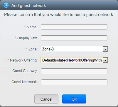
Network Offering. Your choice here determines what network services will be available on the network for guest VMs.
Network Offering
Description
DefaultSharedNetworkOfferingWithSGService
If you want to enable security groups for guest traffic isolation, choose this. (See Using Security Groups to Control Traffic to VMs.)
DefaultSharedNetworkOffering
If you do not need security groups, choose this.
DefaultSharedNetscalerEIPandELBNetworkOffering
If you have installed a Citrix NetScaler appliance as part of your zone network, and you will be using its Elastic IP and Elastic Load Balancing features, choose this. With the EIP and ELB features, a basic zone with security groups enabled can offer 1:1 static NAT and load balancing.
Network Domain. (Optional) If you want to assign a special domain name to the guest VM network, specify the DNS suffix.
Public. A public zone is available to all users. A zone that is not public will be assigned to a particular domain. Only users in that domain will be allowed to create guest VMs in this zone.
Choose which traffic types will be carried by the physical network.
The traffic types are management, public, guest, and storage traffic. For more information about the types, roll over the icons to display their tool tips, or see Basic Zone Network Traffic Types. This screen starts out with some traffic types already assigned. To add more, drag and drop traffic types onto the network. You can also change the network name if desired.
(Introduced in version 3.0.1) Assign a network traffic label to each traffic type on the physical network. These labels must match the labels you have already defined on the hypervisor host. To assign each label, click the Edit button under the traffic type icon. A popup dialog appears where you can type the label, then click OK.
These traffic labels will be defined only for the hypervisor selected for the first cluster. For all other hypervisors, the labels can be configured after the zone is created.
Click Next.
(NetScaler only) If you chose the network offering for NetScaler, you have an additional screen to fill out. Provide the requested details to set up the NetScaler, then click Next.
IP address. The NSIP (NetScaler IP) address of the NetScaler device.
Username/Password. The authentication credentials to access the device. CloudStack uses these credentials to access the device.
Type. NetScaler device type that is being added. It could be NetScaler VPX, NetScaler MPX, or NetScaler SDX. For a comparison of the types, see About Using a NetScaler Load Balancer.
Public interface. Interface of NetScaler that is configured to be part of the public network.
Private interface. Interface of NetScaler that is configured to be part of the private network.
Number of retries. Number of times to attempt a command on the device before considering the operation failed. Default is 2.
Capacity. Number of guest networks/accounts that will share this NetScaler device.
Dedicated. When marked as dedicated, this device will be dedicated to a single account. When Dedicated is checked, the value in the Capacity field has no significance – implicitly, its value is 1.
(NetScaler only) Configure the IP range for public traffic. The IPs in this range will be used for the static NAT capability which you enabled by selecting the network offering for NetScaler with EIP and ELB. Enter the following details, then click Add. If desired, you can repeat this step to add more IP ranges. When done, click Next.
Gateway. The gateway in use for these IP addresses.
Netmask. The netmask associated with this IP range.
VLAN. The VLAN that will be used for public traffic.
Start IP/End IP. A range of IP addresses that are assumed to be accessible from the Internet and will be allocated for access to guest VMs.
In a new zone, CloudStack adds the first pod for you. You can always add more pods later. For an overview of what a pod is, see Section 2.2, “About Pods”.
To configure the first pod, enter the following, then click Next:
Pod Name. A name for the pod.
Reserved system gateway. The gateway for the hosts in that pod.
Reserved system netmask. The network prefix that defines the pod's subnet. Use CIDR notation.
Start/End Reserved System IP. The IP range in the management network that CloudStack uses to manage various system VMs, such as Secondary Storage VMs, Console Proxy VMs, and DHCP. For more information, see System Reserved IP Addresses.
Configure the network for guest traffic. Provide the following, then click Next:
Guest gateway. The gateway that the guests should use.
Guest netmask. The netmask in use on the subnet the guests will use.
Guest start IP/End IP. Enter the first and last IP addresses that define a range that CloudStack can assign to guests.
We strongly recommend the use of multiple NICs. If multiple NICs are used, they may be in a different subnet.
If one NIC is used, these IPs should be in the same CIDR as the pod CIDR.
In a new pod, CloudStack adds the first cluster for you. You can always add more clusters later. For an overview of what a cluster is, see About Clusters.
To configure the first cluster, enter the following, then click Next:
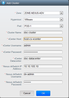
Hypervisor. (Version 3.0.0 only; in 3.0.1, this field is read only) Choose the type of hypervisor software that all hosts in this cluster will run. If you choose VMware, additional fields appear so you can give information about a vSphere cluster. For vSphere servers, we recommend creating the cluster of hosts in vCenter and then adding the entire cluster to CloudStack. See Add Cluster: vSphere.
Cluster name. Enter a name for the cluster. This can be text of your choosing and is not used by CloudStack.
In a new cluster, CloudStack adds the first host for you. You can always add more hosts later. For an overview of what a host is, see About Hosts.
Note
When you add a hypervisor host to CloudStack, the host must not have any VMs already running.
Before you can configure the host, you need to install the hypervisor software on the host. You will need to know which version of the hypervisor software version is supported by CloudStack and what additional configuration is required to ensure the host will work with CloudStack. To find these installation details, see:
Citrix XenServer Installation and Configuration
VMware vSphere Installation and Configuration
KVM vSphere Installation and Configuration
To configure the first host, enter the following, then click Next:
Host Name. The DNS name or IP address of the host.
Username. The username is root.
Password. This is the password for the user named above (from your XenServer or KVM install).
Host Tags. (Optional) Any labels that you use to categorize hosts for ease of maintenance. For example, you can set this to the cloud's HA tag (set in the ha.tag global configuration parameter) if you want this host to be used only for VMs with the "high availability" feature enabled. For more information, see HA-Enabled Virtual Machines as well as HA for Hosts.
In a new cluster, CloudPlatform adds the first primary storage server for you. You can always add more servers later. For an overview of what primary storage is, see About Primary Storage.
To configure the first primary storage server, enter the following, then click Next:
Name. The name of the storage device.
Protocol. For XenServer, choose either NFS, iSCSI, or PreSetup. For KVM, choose NFS, SharedMountPoint,CLVM, or RBD. For vSphere choose either VMFS (iSCSI or FiberChannel) or NFS. The remaining fields in the screen vary depending on what you choose here.
7.2.2. Advanced Zone Configuration
After you select Advanced in the Add Zone wizard and click Next, you will be asked to enter the following details. Then click Next.
Name. A name for the zone.
DNS 1 and 2. These are DNS servers for use by guest VMs in the zone. These DNS servers will be accessed via the public network you will add later. The public IP addresses for the zone must have a route to the DNS server named here.
Internal DNS 1 and Internal DNS 2. These are DNS servers for use by system VMs in the zone(these are VMs used by CloudStack itself, such as virtual routers, console proxies,and Secondary Storage VMs.) These DNS servers will be accessed via the management traffic network interface of the System VMs. The private IP address you provide for the pods must have a route to the internal DNS server named here.
Network Domain. (Optional) If you want to assign a special domain name to the guest VM network, specify the DNS suffix.
Guest CIDR. This is the CIDR that describes the IP addresses in use in the guest virtual networks in this zone. For example, 10.1.1.0/24. As a matter of good practice you should set different CIDRs for different zones. This will make it easier to set up VPNs between networks in different zones.
Hypervisor. (Introduced in version 3.0.1) Choose the hypervisor for the first cluster in the zone. You can add clusters with different hypervisors later, after you finish adding the zone.
Public. A public zone is available to all users. A zone that is not public will be assigned to a particular domain. Only users in that domain will be allowed to create guest VMs in this zone.
Choose which traffic types will be carried by the physical network.
The traffic types are management, public, guest, and storage traffic. For more information about the types, roll over the icons to display their tool tips, or see Section 2.7.4, “Advanced Zone Network Traffic Types”. This screen starts out with one network already configured. If you have multiple physical networks, you need to add more. Drag and drop traffic types onto a greyed-out network and it will become active. You can move the traffic icons from one network to another; for example, if the default traffic types shown for Network 1 do not match your actual setup, you can move them down. You can also change the network names if desired.
(Introduced in version 3.0.1) Assign a network traffic label to each traffic type on each physical network. These labels must match the labels you have already defined on the hypervisor host. To assign each label, click the Edit button under the traffic type icon within each physical network. A popup dialog appears where you can type the label, then click OK.
These traffic labels will be defined only for the hypervisor selected for the first cluster. For all other hypervisors, the labels can be configured after the zone is created.
Click Next.
Configure the IP range for public Internet traffic. Enter the following details, then click Add. If desired, you can repeat this step to add more public Internet IP ranges. When done, click Next.
Gateway. The gateway in use for these IP addresses.
Netmask. The netmask associated with this IP range.
VLAN. The VLAN that will be used for public traffic.
Start IP/End IP. A range of IP addresses that are assumed to be accessible from the Internet and will be allocated for access to guest networks.
In a new zone, CloudStack adds the first pod for you. You can always add more pods later. For an overview of what a pod is, see Section 2.2, “About Pods”.
To configure the first pod, enter the following, then click Next:
Pod Name. A name for the pod.
Reserved system gateway. The gateway for the hosts in that pod.
Reserved system netmask. The network prefix that defines the pod's subnet. Use CIDR notation.
Start/End Reserved System IP. The IP range in the management network that CloudStack uses to manage various system VMs, such as Secondary Storage VMs, Console Proxy VMs, and DHCP. For more information, see Section 2.7.7, “System Reserved IP Addresses”.
Specify a range of VLAN IDs to carry guest traffic for each physical network (see VLAN Allocation Example ), then click Next.
In a new pod, CloudStack adds the first cluster for you. You can always add more clusters later. For an overview of what a cluster is, see Section 2.3, “About Clusters”.
To configure the first cluster, enter the following, then click Next:
Hypervisor. (Version 3.0.0 only; in 3.0.1, this field is read only) Choose the type of hypervisor software that all hosts in this cluster will run. If you choose VMware, additional fields appear so you can give information about a vSphere cluster. For vSphere servers, we recommend creating the cluster of hosts in vCenter and then adding the entire cluster to CloudStack. See Add Cluster: vSphere .
Cluster name. Enter a name for the cluster. This can be text of your choosing and is not used by CloudStack.
In a new cluster, CloudStack adds the first host for you. You can always add more hosts later. For an overview of what a host is, see Section 2.4, “About Hosts”.
Note
When you deploy CloudStack, the hypervisor host must not have any VMs already running.
Before you can configure the host, you need to install the hypervisor software on the host. You will need to know which version of the hypervisor software version is supported by CloudStack and what additional configuration is required to ensure the host will work with CloudStack. To find these installation details, see:
Citrix XenServer Installation for CloudStack
VMware vSphere Installation and Configuration
KVM Installation and Configuration
To configure the first host, enter the following, then click Next:
Host Name. The DNS name or IP address of the host.
Username. Usually root.
Password. This is the password for the user named above (from your XenServer or KVM install).
Host Tags. (Optional) Any labels that you use to categorize hosts for ease of maintenance. For example, you can set to the cloud's HA tag (set in the ha.tag global configuration parameter) if you want this host to be used only for VMs with the "high availability" feature enabled. For more information, see HA-Enabled Virtual Machines as well as HA for Hosts, both in the Administration Guide.
In a new cluster, CloudStack adds the first primary storage server for you. You can always add more servers later. For an overview of what primary storage is, see Section 2.5, “About Primary Storage”.
To configure the first primary storage server, enter the following, then click Next:
Name. The name of the storage device.
Protocol. For XenServer, choose either NFS, iSCSI, or PreSetup. For KVM, choose NFS, SharedMountPoint, CLVM, and RBD. For vSphere choose either VMFS (iSCSI or FiberChannel) or NFS. The remaining fields in the screen vary depending on what you choose here.
NFS
Server. The IP address or DNS name of the storage device.
Path. The exported path from the server.
Tags (optional). The comma-separated list of tags for this storage device. It should be an equivalent set or superset of the tags on your disk offerings.
The tag sets on primary storage across clusters in a Zone must be identical. For example, if cluster A provides primary storage that has tags T1 and T2, all other clusters in the Zone must also provide primary storage that has tags T1 and T2.
iSCSI
Server. The IP address or DNS name of the storage device.
Target IQN. The IQN of the target. For example, iqn.1986-03.com.sun:02:01ec9bb549-1271378984.
Lun. The LUN number. For example, 3.
Tags (optional). The comma-separated list of tags for this storage device. It should be an equivalent set or superset of the tags on your disk offerings.
The tag sets on primary storage across clusters in a Zone must be identical. For example, if cluster A provides primary storage that has tags T1 and T2, all other clusters in the Zone must also provide primary storage that has tags T1 and T2.
preSetup
Server. The IP address or DNS name of the storage device.
SR Name-Label. Enter the name-label of the SR that has been set up outside CloudStack.
Tags (optional). The comma-separated list of tags for this storage device. It should be an equivalent set or superset of the tags on your disk offerings.
The tag sets on primary storage across clusters in a Zone must be identical. For example, if cluster A provides primary storage that has tags T1 and T2, all other clusters in the Zone must also provide primary storage that has tags T1 and T2.
SharedMountPoint
Path. The path on each host that is where this primary storage is mounted. For example, "/mnt/primary".
Tags (optional). The comma-separated list of tags for this storage device. It should be an equivalent set or superset of the tags on your disk offerings.
The tag sets on primary storage across clusters in a Zone must be identical. For example, if cluster A provides primary storage that has tags T1 and T2, all other clusters in the Zone must also provide primary storage that has tags T1 and T2.
VMFS
Server. The IP address or DNS name of the vCenter server.
Path. A combination of the datacenter name and the datastore name. The format is "/" datacenter name "/" datastore name. For example, "/cloud.dc.VM/cluster1datastore".
Tags (optional). The comma-separated list of tags for this storage device. It should be an equivalent set or superset of the tags on your disk offerings.
The tag sets on primary storage across clusters in a Zone must be identical. For example, if cluster A provides primary storage that has tags T1 and T2, all other clusters in the Zone must also provide primary storage that has tags T1 and T2.
In a new zone, CloudStack adds the first secondary storage server for you. For an overview of what secondary storage is, see Section 2.6, “About Secondary Storage”.
Before you can fill out this screen, you need to prepare the secondary storage by setting up NFS shares and installing the latest CloudStack System VM template. See Adding Secondary Storage :
NFS Server. The IP address of the server.
Path. The exported path from the server.
Click Launch.
7.3. Adding a Pod
When you created a new zone, CloudStack adds the first pod for you. You can add more pods at any time using the procedure in this section.
In the left navigation, choose Infrastructure. In Zones, click View More, then click the zone to which you want to add a pod.
Click the Compute and Storage tab. In the Pods node of the diagram, click View All.
Click Add Pod.
Enter the following details in the dialog.
Name. The name of the pod.
Gateway. The gateway for the hosts in that pod.
Netmask. The network prefix that defines the pod's subnet. Use CIDR notation.
Start/End Reserved System IP. The IP range in the management network that CloudStack uses to manage various system VMs, such as Secondary Storage VMs, Console Proxy VMs, and DHCP. For more information, see System Reserved IP Addresses.
Click OK.
7.4. Adding a Cluster
You need to tell CloudStack about the hosts that it will manage. Hosts exist inside clusters, so before you begin adding hosts to the cloud, you must add at least one cluster.
7.4.1. Add Cluster: KVM or XenServer
These steps assume you have already installed the hypervisor on the hosts and logged in to the CloudStack UI.
In the left navigation, choose Infrastructure. In Zones, click View More, then click the zone in which you want to add the cluster.
Click the Compute tab.
In the Clusters node of the diagram, click View All.
Click Add Cluster.
Choose the hypervisor type for this cluster.
Choose the pod in which you want to create the cluster.
Enter a name for the cluster. This can be text of your choosing and is not used by CloudStack.
Click OK.
7.4.2. Add Cluster: vSphere
Host management for vSphere is done through a combination of vCenter and the CloudStack admin UI. CloudStack requires that all hosts be in a CloudStack cluster, but the cluster may consist of a single host. As an administrator you must decide if you would like to use clusters of one host or of multiple hosts. Clusters of multiple hosts allow for features like live migration. Clusters also require shared storage such as NFS or iSCSI.
For vSphere servers, we recommend creating the cluster of hosts in vCenter and then adding the entire cluster to CloudStack. Follow these requirements:
Do not put more than 8 hosts in a vSphere cluster
Make sure the hypervisor hosts do not have any VMs already running before you add them to CloudStack.
To add a vSphere cluster to CloudStack:
Create the cluster of hosts in vCenter. Follow the vCenter instructions to do this. You will create a cluster that looks something like this in vCenter.
Log in to the UI.
In the left navigation, choose Infrastructure. In Zones, click View More, then click the zone in which you want to add the cluster.
Click the Compute tab, and click View All on Pods. Choose the pod to which you want to add the cluster.
Click View Clusters.
Click Add Cluster.
In Hypervisor, choose VMware.
Provide the following information in the dialog. The fields below make reference to values from vCenter.
Cluster Name. Enter the name of the cluster you created in vCenter. For example, "cloud.cluster.2.2.1"
vCenter Host. Enter the hostname or IP address of the vCenter server.
vCenter Username. Enter the username that CloudStack should use to connect to vCenter. This user must have all administrative privileges.
vCenter Password. Enter the password for the user named above
vCenter Datacenter. Enter the vCenter datacenter that the cluster is in. For example, "cloud.dc.VM".
There might be a slight delay while the cluster is provisioned. It will automatically display in the UI
7.5. Adding a Host
Before adding a host to the CloudStack configuration, you must first install your chosen hypervisor on the host. CloudStack can manage hosts running VMs under a variety of hypervisors.
The CloudStack Installation Guide provides instructions on how to install each supported hypervisor and configure it for use with CloudStack. See the appropriate section in the Installation Guide for information about which version of your chosen hypervisor is supported, as well as crucial additional steps to configure the hypervisor hosts for use with CloudStack.
Warning
Be sure you have performed the additional CloudStack-specific configuration steps described in the hypervisor installation section for your particular hypervisor.
Now add the hypervisor host to CloudStack. The technique to use varies depending on the hypervisor.
When copying and pasting a command, be sure the command has pasted as a single line before executing. Some document viewers may introduce unwanted line breaks in copied text.
With all hosts added to the XenServer pool, run the cloud-setup-bond script. This script will complete the configuration and setup of the bonds on the new hosts in the cluster.
Copy the script from the Management Server in /usr/lib64/cloud/common/scripts/vm/hypervisor/xenserver/cloud-setup-bonding.sh to the master host and ensure it is executable.
Run the script:
# ./cloud-setup-bonding.sh
7.5.1.1.2. KVM Host Additional Requirements
If shared mountpoint storage is in use, the administrator should ensure that the new host has all the same mountpoints (with storage mounted) as the other hosts in the cluster.
Make sure the new host has the same network configuration (guest, private, and public network) as other hosts in the cluster.
7.5.1.2. Adding a XenServer or KVM Host
If you have not already done so, install the hypervisor software on the host. You will need to know which version of the hypervisor software version is supported by CloudStack and what additional configuration is required to ensure the host will work with CloudStack. To find these installation details, see the appropriate section for your hypervisor in the CloudStack Installation Guide.
Log in to the CloudStack UI as administrator.
In the left navigation, choose Infrastructure. In Zones, click View More, then click the zone in which you want to add the host.
Click the Compute tab. In the Clusters node, click View All.
Click the cluster where you want to add the host.
Click View Hosts.
Click Add Host.
Provide the following information.
Host Name. The DNS name or IP address of the host.
Username. Usually root.
Password. This is the password for the user from your XenServer or KVM install).
Host Tags (Optional). Any labels that you use to categorize hosts for ease of maintenance. For example, you can set to the cloud's HA tag (set in the ha.tag global configuration parameter) if you want this host to be used only for VMs with the "high availability" feature enabled. For more information, see HA-Enabled Virtual Machines as well as HA for Hosts.
There may be a slight delay while the host is provisioned. It should automatically display in the UI.
Repeat for additional hosts.
7.5.2. Adding a Host (vSphere)
For vSphere servers, we recommend creating the cluster of hosts in vCenter and then adding the entire cluster to CloudStack. See Add Cluster: vSphere.
7.6. Add Primary Storage
7.6.1. System Requirements for Primary Storage
Hardware requirements:
Any standards-compliant iSCSI or NFS server that is supported by the underlying hypervisor.
The storage server should be a machine with a large number of disks. The disks should ideally be managed by a hardware RAID controller.
Minimum required capacity depends on your needs.
When setting up primary storage, follow these restrictions:
Primary storage cannot be added until a host has been added to the cluster.
If you do not provision shared primary storage, you must set the global configuration parameter system.vm.local.storage.required to true, or else you will not be able to start VMs.
7.6.2. Adding Primary Stroage
When you create a new zone, the first primary storage is added as part of that procedure. You can add primary storage servers at any time, such as when adding a new cluster or adding more servers to an existing cluster.
Warning
Be sure there is nothing stored on the server. Adding the server to CloudStack will destroy any existing data.
In the left navigation, choose Infrastructure. In Zones, click View More, then click the zone in which you want to add the primary storage.
Click the Compute tab.
In the Primary Storage node of the diagram, click View All.
Click Add Primary Storage.
Provide the following information in the dialog. The information required varies depending on your choice in Protocol.
Pod. The pod for the storage device.
Cluster. The cluster for the storage device.
Name. The name of the storage device.
Protocol. For XenServer, choose either NFS, iSCSI, or PreSetup. For KVM, choose NFS or SharedMountPoint. For vSphere choose either VMFS (iSCSI or FiberChannel) or NFS.
Server (for NFS, iSCSI, or PreSetup). The IP address or DNS name of the storage device.
Server (for VMFS). The IP address or DNS name of the vCenter server.
Path (for NFS). In NFS this is the exported path from the server.
Path (for VMFS). In vSphere this is a combination of the datacenter name and the datastore name. The format is "/" datacenter name "/" datastore name. For example, "/cloud.dc.VM/cluster1datastore".
Path (for SharedMountPoint). With KVM this is the path on each host that is where this primary storage is mounted. For example, "/mnt/primary".
SR Name-Label (for PreSetup). Enter the name-label of the SR that has been set up outside CloudStack.
Target IQN (for iSCSI). In iSCSI this is the IQN of the target. For example, iqn.1986-03.com.sun:02:01ec9bb549-1271378984.
Lun # (for iSCSI). In iSCSI this is the LUN number. For example, 3.
Tags (optional). The comma-separated list of tags for this storage device. It should be an equivalent set or superset of the tags on your disk offerings..
The tag sets on primary storage across clusters in a Zone must be identical. For example, if cluster A provides primary storage that has tags T1 and T2, all other clusters in the Zone must also provide primary storage that has tags T1 and T2.
Click OK.
7.7. Add Secondary Storage
7.7.1. System Requirements for Secondary Storage
NFS storage appliance or Linux NFS server
(Optional) OpenStack Object Storage (Swift) (see http://swift.openstack.org)
100GB minimum capacity
A secondary storage device must be located in the same zone as the guest VMs it serves.
Each Secondary Storage server must be available to all hosts in the zone.
7.7.2. Adding Secondary Storage
When you create a new zone, the first secondary storage is added as part of that procedure. You can add secondary storage servers at any time to add more servers to an existing zone.
Warning
Be sure there is nothing stored on the server. Adding the server to CloudStack will destroy any existing data.
If you are going to use Swift for cloud-wide secondary storage, you must add the Swift storage to CloudStack before you add the local zone secondary storage servers. See Section 7.2, “Adding a Zone”.
To prepare for local zone secondary storage, you should have created and mounted an NFS share during Management Server installation. See Preparing NFS Shares in the Installation Guide.
Make sure you prepared the system VM template during Management Server installation. See Prepare the System VM Template in the Installation Guide.
Now that the secondary storage server for per-zone storage is prepared, add it to CloudStack. Secondary storage is added as part of the procedure for adding a new zone. See Section 7.2, “Adding a Zone”.
7.8. Initialize and Test
After everything is configured, CloudStack will perform its initialization. This can take 30 minutes or more, depending on the speed of your network. When the initialization has completed successfully, the administrator's Dashboard should be displayed in the CloudStack UI.
Verify that the system is ready. In the left navigation bar, select Templates. Click on the CentOS 5.5 (64bit) no Gui (KVM) template. Check to be sure that the status is "Download Complete." Do not proceed to the next step until this status is displayed.
Go to the Instances tab, and filter by My Instances.
Click Add Instance and follow the steps in the wizard.
Choose the zone you just added.
In the template selection, choose the template to use in the VM. If this is a fresh installation, likely only the provided CentOS template is available.
Select a service offering. Be sure that the hardware you have allows starting the selected service offering.
In data disk offering, if desired, add another data disk. This is a second volume that will be available to but not mounted in the guest. For example, in Linux on XenServer you will see /dev/xvdb in the guest after rebooting the VM. A reboot is not required if you have a PV-enabled OS kernel in use.
In default network, choose the primary network for the guest. In a trial installation, you would have only one option here.
Optionally give your VM a name and a group. Use any descriptive text you would like.
Click Launch VM. Your VM will be created and started. It might take some time to download the template and complete the VM startup. You can watch the VM’s progress in the Instances screen.
To use the VM, click the View Console button.
Congratulations! You have successfully completed a CloudStack Installation.
If you decide to grow your deployment, you can add more hosts, primary storage, zones, pods, and clusters.
In this chapter we discuss compute, disk, and system service offerings. Network offerings are discussed in the section on setting up networking for users.
8.1. Compute and Disk Service Offerings
A service offering is a set of virtual hardware features such as CPU core count and speed, memory, and disk size. The CloudStack administrator can set up various offerings, and then end users choose from the available offerings when they create a new VM. A service offering includes the following elements:
CPU, memory, and network resource guarantees
How resources are metered
How the resource usage is charged
How often the charges are generated
For example, one service offering might allow users to create a virtual machine instance that is equivalent to a 1 GHz Intel® Core™ 2 CPU, with 1 GB memory at $0.20/hour, with network traffic metered at $0.10/GB. Based on the user’s selected offering, CloudStack emits usage records that can be integrated with billing systems. CloudStack separates service offerings into compute offerings and disk offerings. The computing service offering specifies:
Guest CPU
Guest RAM
Guest Networking type (virtual or direct)
Tags on the root disk
The disk offering specifies:
Disk size (optional). An offering without a disk size will allow users to pick their own
Tags on the data disk
8.1.1. Creating a New Compute Offering
To create a new compute offering:
Log in with admin privileges to the CloudStack UI.
In the left navigation bar, click Service Offerings.
In Select Offering, choose Compute Offering.
Click Add Compute Offering.
In the dialog, make the following choices:
Name: Any desired name for the service offering.
Description: A short description of the offering that can be displayed to users
Storage type: The type of disk that should be allocated. Local allocates from storage attached directly to the host where the system VM is running. Shared allocates from storage accessible via NFS.
# of CPU cores: The number of cores which should be allocated to a system VM with this offering
CPU (in MHz): The CPU speed of the cores that the system VM is allocated. For example, “2000” would provide for a 2 GHz clock.
Memory (in MB): The amount of memory in megabytes that the system VM should be allocated. For example, “2048” would provide for a 2 GB RAM allocation.
Network Rate: Allowed data transfer rate in MB per second.
Offer HA: If yes, the administrator can choose to have the system VM be monitored and as highly available as possible.
Storage Tags: The tags that should be associated with the primary storage used by the system VM.
Host Tags: (Optional) Any tags that you use to organize your hosts
CPU cap: Whether to limit the level of CPU usage even if spare capacity is available.
Public: Indicate whether the service offering should be available all domains or only some domains. Choose Yes to make it available to all domains. Choose No to limit the scope to a subdomain; CloudStack will then prompt for the subdomain's name.
Click Add.
8.1.2. Creating a New Disk Offering
To create a system service offering:
Log in with admin privileges to the CloudStack UI.
In the left navigation bar, click Service Offerings.
In Select Offering, choose Disk Offering.
Click Add Disk Offering.
In the dialog, make the following choices:
Name. Any desired name for the system offering.
Description. A short description of the offering that can be displayed to users
Custom Disk Size. If checked, the user can set their own disk size. If not checked, the root administrator must define a value in Disk Size.
Disk Size. Appears only if Custom Disk Size is not selected. Define the volume size in GB.
(Optional)Storage Tags. The tags that should be associated with the primary storage for this disk. Tags are a comma separated list of attributes of the storage. For example "ssd,blue". Tags are also added on Primary Storage. CloudStack matches tags on a disk offering to tags on the storage. If a tag is present on a disk offering that tag (or tags) must also be present on Primary Storage for the volume to be provisioned. If no such primary storage exists, allocation from the disk offering will fail..
Public. Indicate whether the service offering should be available all domains or only some domains. Choose Yes to make it available to all domains. Choose No to limit the scope to a subdomain; CloudStack will then prompt for the subdomain's name.
Click Add.
8.1.3. Modifying or Deleting a Service Offering
Service offerings cannot be changed once created. This applies to both compute offerings and disk offerings.
A service offering can be deleted. If it is no longer in use, it is deleted immediately and permanently. If the service offering is still in use, it will remain in the database until all the virtual machines referencing it have been deleted. After deletion by the administrator, a service offering will not be available to end users that are creating new instances.
8.2. System Service Offerings
System service offerings provide a choice of CPU speed, number of CPUs, tags, and RAM size, just as other service offerings do. But rather than being used for virtual machine instances and exposed to users, system service offerings are used to change the default properties of virtual routers, console proxies, and other system VMs. System service offerings are visible only to the CloudStack root administrator. CloudStack provides default system service offerings. The CloudStack root administrator can create additional custom system service offerings.
When CloudStack creates a virtual router for a guest network, it uses default settings which are defined in the system service offering associated with the network offering. You can upgrade the capabilities of the virtual router by applying a new network offering that contains a different system service offering. All virtual routers in that network will begin using the settings from the new service offering.
People using cloud infrastructure have a variety of needs and preferences when it comes to the networking services provided by the cloud. As a CloudStack administrator, you can do the following things to set up networking for your users:
Set up physical networks in zones
Set up several different providers for the same service on a single physical network (for example, both Cisco and Juniper firewalls)
Bundle different types of network services into network offerings, so users can choose the desired network services for any given virtual machine
Add new network offerings as time goes on so end users can upgrade to a better class of service on their network
Provide more ways for a network to be accessed by a user, such as through a project of which the user is a member
9.2. About Virtual Networks
A virtual network is a logical construct that enables multi-tenancy on a single physical network. In CloudStack a virtual network can be shared or isolated.
9.2.1. Isolated Networks
An isolated network can be accessed only by virtual machines of a single account. Isolated networks have the following properties.
Resources such as VLAN are allocated and garbage collected dynamically
There is one network offering for the entire network
The network offering can be upgraded or downgraded but it is for the entire network
9.2.2. Shared Networks
A shared network can be accessed by virtual machines that belong to many different accounts. Network Isolation on shared networks is accomplished using techniques such as security groups (supported only in basic zones in CloudStack 3.0.3).
Shared Networks are created by the administrator
Shared Networks can be designated to a certain domain
Shared Network resources such as VLAN and physical network that it maps to are designated by the administrator
Shared Networks are isolated by security groups
Public Network is a shared network that is not shown to the end users
9.2.3. Runtime Allocation of Virtual Network Resources
When you define a new virtual network, all your settings for that network are stored in CloudStack. The actual network resources are activated only when the first virtual machine starts in the network. When all virtual machines have left the virtual network, the network resources are garbage collected so they can be allocated again. This helps to conserve network resources..
9.3. Network Service Providers
Note
For the most up-to-date list of supported network service providers, see the CloudPlatform UI or call listNetworkServiceProviders.
A service provider (also called a network element) is hardware or virtual appliance that makes a network service possible; for example, a firewall appliance can be installed in the cloud to provide firewall service. On a single network, multiple providers can provide the same network service. For example, a firewall service may be provided by Cisco or Juniper devices in the same physical network.
You can have multiple instances of the same service provider in a network (say, more than one Juniper SRX device).
If different providers are set up to provide the same service on the network, the administrator can create network offerings so users can specify which network service provider they prefer (along with the other choices offered in network offerings). Otherwise, CloudPlatform will choose which provider to use whenever the service is called for.
Supported Network Service Providers
CloudPlatform ships with an internal list of the supported service providers, and you can choose from this list when creating a network offering.
9.4. Network Offerings
Note
For the most up-to-date list of supported network services, see the CloudPlatform UI or call listNetworkServices.
A network offering is a named set of network services, such as:
DHCP
DNS
Source NAT
Static NAT
Port Forwarding
Load Balancing
Firewall
VPN
Optional) Name one of several available providers to use for a given service, such as Juniper for the firewall
(Optional) Network tag to specify which physical network to use
When creating a new VM, the user chooses one of the available network offerings, and that determines which network services the VM can use.
The CloudPlatform administrator can create any number of custom network offerings, in addition to the default network offerings provided by CloudPlatform. By creating multiple custom network offerings, you can set up your cloud to offer different classes of service on a single multi-tenant physical network. For example, while the underlying physical wiring may be the same for two tenants, tenant A may only need simple firewall protection for their website, while tenant B may be running a web server farm and require a scalable firewall solution, load balancing solution, and alternate networks for accessing the database backend.
Note
If you create load balancing rules while using a network service offering that includes an external load balancer device such as NetScaler, and later change the network service offering to one that uses the CloudPlatform virtual router, you must create a firewall rule on the virtual router for each of your existing load balancing rules so that they continue to function.
When creating a new virtual network, the CloudPlatform administrator chooses which network offering to enable for that network. Each virtual network is associated with one network offering. A virtual network can be upgraded or downgraded by changing its associated network offering. If you do this, be sure to reprogram the physical network to match.
CloudPlatform also has internal network offerings for use by CloudPlatform system VMs. These network offerings are not visible to users but can be modified by administrators.
CloudStack provides administrators with complete control over the lifecycle of all guest VMs executing in the cloud. CloudStack provides several guest management operations for end users and administrators. VMs may be stopped, started, rebooted, and destroyed.
Guest VMs have a name and group. VM names and groups are opaque to CloudStack and are available for end users to organize their VMs. Each VM can have three names for use in different contexts. Only two of these names can be controlled by the user:
Instance name – a unique, immutable ID that is generated by CloudStack and can not be modified by the user. This name conforms to the requirements in IETF RFC 1123.
Display name – the name displayed in the CloudStack web UI. Can be set by the user. Defaults to instance name.
Name – host name that the DHCP server assigns to the VM. Can be set by the user. Defaults to instance name
Guest VMs can be configured to be Highly Available (HA). An HA-enabled VM is monitored by the system. If the system detects that the VM is down, it will attempt to restart the VM, possibly on a different host. For more information, see HA-Enabled Virtual Machines on
Each new VM is allocated one public IP address. When the VM is started, CloudStack automatically creates a static NAT between this public IP address and the private IP address of the VM.
If elastic IP is in use (with the NetScaler load balancer), the IP address initially allocated to the new VM is not marked as elastic. The user must replace the automatically configured IP with a specifically acquired elastic IP, and set up the static NAT mapping between this new IP and the guest VM’s private IP. The VM’s original IP address is then released and returned to the pool of available public IPs.
CloudStack cannot distinguish a guest VM that was shut down by the user (such as with the “shutdown” command in Linux) from a VM that shut down unexpectedly. If an HA-enabled VM is shut down from inside the VM, CloudStack will restart it. To shut down an HA-enabled VM, you must go through the CloudStack UI or API.
10.2. Best Practices for Virtual Machines
The CloudStack administrator should monitor the total number of VM instances in each cluster, and disable allocation to the cluster if the total is approaching the maximum that the hypervisor can handle. Be sure to leave a safety margin to allow for the possibility of one or more hosts failing, which would increase the VM load on the other hosts as the VMs are automatically redeployed. Consult the documentation for your chosen hypervisor to find the maximum permitted number of VMs per host, then use CloudStack global configuration settings to set this as the default limit. Monitor the VM activity in each cluster at all times. Keep the total number of VMs below a safe level that allows for the occasional host failure. For example, if there are N hosts in the cluster, and you want to allow for one host in the cluster to be down at any given time, the total number of VM instances you can permit in the cluster is at most (N-1) * (per-host-limit). Once a cluster reaches this number of VMs, use the CloudStack UI to disable allocation of more VMs to the cluster.
10.3. VM Lifecycle
Virtual machines can be in the following states:
Once a virtual machine is destroyed, it cannot be recovered. All the resources used by the virtual machine will be reclaimed by the system. This includes the virtual machine’s IP address.
A stop will attempt to gracefully shut down the operating system, which typically involves terminating all the running applications. If the operation system cannot be stopped, it will be forcefully terminated. This has the same effect as pulling the power cord to a physical machine.
A reboot is a stop followed by a start.
CloudPlatform preserves the state of the virtual machine hard disk until the machine is destroyed.
A running virtual machine may fail because of hardware or network issues. A failed virtual machine is in the down state.
The system places the virtual machine into the down state if it does not receive the heartbeat from the hypervisor for three minutes.
The user can manually restart the virtual machine from the down state.
The system will start the virtual machine from the down state automatically if the virtual machine is marked as HA-enabled.
10.4. Creating VMs
Virtual machines are usually created from a template. Users can also create blank virtual machines. A blank virtual machine is a virtual machine without an OS template. Users can attach an ISO file and install the OS from the CD/DVD-ROM.
To create a VM from a template:
Log in to the CloudStack UI as an administrator or user.
In the left navigation bar, click Instances.
Click Add Instance.
Select a template, then follow the steps in the wizard. (For more information about how the templates came to be in this list, see Working with Templates.
Be sure that the hardware you have allows starting the selected service offering.
Click Submit and your VM will be created and started.
Note
For security reason, the internal name of the VM is visible only to the root admin.
Note
Starting with v3.0.3, you can create a VM without starting it. You can determine whether the VM needs to be started as part of the VM deployment. A new request parameter, startVM, is introduced in the deployVm API to support this feature. For more information, see the Developer's Guide
To create a VM from an ISO:
Note
(XenServer) Windows VMs running on XenServer require PV drivers, which may be provided in the template or added after the VM is created. The PV drivers are necessary for essential management functions such as mounting additional volumes and ISO images, live migration, and graceful shutdown.
Log in to the CloudStack UI as an administrator or user.
In the left navigation bar, click Instances.
Click Add Instance.
Select ISO Boot, and follow the steps in the wizard.
Click Submit and your VM will be created and started.
10.5. Accessing VMs
Any user can access their own virtual machines. The administrator can access all VMs running in the cloud.
To access a VM through the CloudStack UI:
Log in to the CloudStack UI as a user or admin.
Click Instances, then click the name of a running VM.
Click the View Console button .
To access a VM directly over the network:
The VM must have some port open to incoming traffic. For example, in a basic zone, a new VM might be assigned to a security group which allows incoming traffic. This depends on what security group you picked when creating the VM. In other cases, you can open a port by setting up a port forwarding policy. See IP Forwarding and Firewalling.
If a port is open but you can not access the VM using ssh, it’s possible that ssh is not already enabled on the VM. This will depend on whether ssh is enabled in the template you picked when creating the VM. Access the VM through the CloudStack UI and enable ssh on the machine using the commands for the VM’s operating system.
If the network has an external firewall device, you will need to create a firewall rule to allow access. See IP Forwarding and Firewalling.
10.6. Stopping and Starting VMs
Any user can access their own virtual machines. The administrator can access all VMs running in the cloud.
10.7. Changing the VM Name, OS, or Group
After a VM is created, you can modify the display name, operating system, and the group it belongs to.
To access a VM through the CloudStack UI:
Log in to the CloudStack UI as a user or admin.
In the left navigation, click Instances.
Select the VM that you want to modify.
Click the Stop button to stop the VM
Click Edit
.
Make the desired changes to the following:
Display name: Enter a new display name if you want to change the name of the VM.
OS Type: Select the desired operating system.
Group: Enter the group name for the VM.
Click Apply.
10.8. Changing the Service Offering for a VM
To upgrade or downgrade the level of compute resources available to a virtual machine, you can change the VM's compute offering.
Log in to the CloudStack UI as a user or admin.
In the left navigation, click Instances.
Choose the VM that you want to work with.
Click the Stop button to stop the VM
Click the Change Service button
. The Change service dialog box is displayed.
Select the offering you want.
Click OK.
10.9. Moving VMs Between Hosts (Manual Live Migration)
The CloudPlatform administrator can move a running VM from one host to another without interrupting service to users or going into maintenance mode. This is called manual live migration, and can be done under the following conditions:
The root administrator is logged in. Domain admins and users can not perform manual live migration of VMs.
The VM is running. Stopped VMs can not be live migrated.
The destination host must be in the same cluster as the original host.
The VM must not be using local disk storage.
The destination host must have enough available capacity. If not, the VM will remain in the "migrating" state until memory becomes available.
To manually live migrate a virtual machine
Log in to the CloudPlatform UI as a user or admin.
In the left navigation, click Instances.
Choose the VM that you want to migrate.
Click the Migrate Instance button
From the list of hosts, choose the one to which you want to move the VM.
Click OK.
10.10. Deleting VMs
Users can delete their own virtual machines. A running virtual machine will be abruptly stopped before it is deleted. Administrators can delete any virtual machines.
To delete a virtual machine:
Log in to the CloudStack UI as a user or admin.
In the left navigation, click Instances.
Choose the VM that you want to delete.
Click the Destroy Instance button
10.11. Working with ISOs
CloudStack supports ISOs and their attachment to guest VMs. An ISO is a read-only file that has an ISO/CD-ROM style file system. Users can upload their own ISOs and mount them on their guest VMs.
ISOs are uploaded based on a URL. HTTP is the supported protocol. Once the ISO is available via HTTP specify an upload URL such as http://my.web.server/filename.iso.
ISOs may be public or private, like templates.ISOs are not hypervisor-specific. That is, a guest on vSphere can mount the exact same image that a guest on KVM can mount.
ISO images may be stored in the system and made available with a privacy level similar to templates. ISO images are classified as either bootable or not bootable. A bootable ISO image is one that contains an OS image. CloudStack allows a user to boot a guest VM off of an ISO image. Users can also attach ISO images to guest VMs. For example, this enables installing PV drivers into Windows. ISO images are not hypervisor-specific.
10.11.1. Adding an ISO
To make additional operating system or other software available for use with guest VMs, you can add an ISO. The ISO is typically thought of as an operating system image, but you can also add ISOs for other types of software, such as desktop applications that you want to be installed as part of a template.
Log in to the CloudStack UI as an administrator or end user.
In the left navigation bar, click Templates.
In Select View, choose ISOs.
Click Add ISO.
In the Add ISO screen, provide the following:
Name: Short name for the ISO image. For example, CentOS 6.2 64-bit.
Description: Display test for the ISO image. For example, CentOS 6.2 64-bit.
URL: The URL that hosts the ISO image. The Management Server must be able to access this location via HTTP. If needed you can place the ISO image directly on the Management Server
Zone: Choose the zone where you want the ISO to be available, or All Zones to make it available throughout CloudStack.
Bootable: Whether or not a guest could boot off this ISO image. For example, a CentOS ISO is bootable, a Microsoft Office ISO is not bootable.
OS Type: This helps CloudStack and the hypervisor perform certain operations and make assumptions that improve the performance of the guest. Select one of the following.
If the operating system of your desired ISO image is listed, choose it.
If the OS Type of the ISO is not listed or if the ISO is not bootable, choose Other.
(XenServer only) If you want to boot from this ISO in PV mode, choose Other PV (32-bit) or Other PV (64-bit)
(KVM only) If you choose an OS that is PV-enabled, the VMs created from this ISO will have a SCSI (virtio) root disk. If the OS is not PV-enabled, the VMs will have an IDE root disk. The PV-enabled types are:
Fedora 13
Fedora 12
Fedora 11
Fedora 10
Fedora 9
Other PV
Debian GNU/Linux
CentOS 5.3
CentOS 5.4
CentOS 5.5
Red Hat Enterprise Linux 5.3
Red Hat Enterprise Linux 5.4
Red Hat Enterprise Linux 5.5
Red Hat Enterprise Linux 6
Note
It is not recommended to choose an older version of the OS than the version in the image. For example, choosing CentOS 5.4 to support a CentOS 6.2 image will usually not work. In these cases, choose Other.
Extractable: Choose Yes if the ISO should be available for extraction.
Public: Choose Yes if this ISO should be available to other users.
Featured: Choose Yes if you would like this ISO to be more prominent for users to select. The ISO will appear in the Featured ISOs list. Only an administrator can make an ISO Featured.
Click OK.
The Management Server will download the ISO. Depending on the size of the ISO, this may take a long time. The ISO status column will display Ready once it has been successfully downloaded into secondary storage. Clicking Refresh updates the download percentage.
Important: Wait for the ISO to finish downloading. If you move on to the next task and try to use the ISO right away, it will appear to fail. The entire ISO must be available before CloudStack can work with it.
10.11.2. Attaching an ISO to a VM
In the left navigation, click Instances.
Choose the virtual machine you want to work with.
Click the Attach ISO button
In the Attach ISO dialog box, select the desired ISO.
Additional hosts can be added at any time to provide more capacity for guest VMs. For requirements and instructions, see Section 7.5, “Adding a Host”.
11.2. Scheduled Maintenance and Maintenance Mode for Hosts
You can place a host into maintenance mode. When maintenance mode is activated, the host becomes unavailable to receive new guest VMs, and the guest VMs already running on the host are seamlessly migrated to another host not in maintenance mode. This migration uses live migration technology and does not interrupt the execution of the guest.
11.3. Disabling and Enabling Zones, Pods, and Clusters
You can enable or disable a zone, pod, or cluster without permanently removing it from the cloud. This is useful for maintenance or when there are problems that make a portion of the cloud infrastructure unreliable. No new allocations will be made to a disabled zone, pod, or cluster until its state is returned to Enabled. When a zone, pod, or cluster is first added to the cloud, it is Disabled by default.
To disable and enable a zone, pod, or cluster:
Log in to the CloudStack UI as administrator
In the left navigation bar, click Infrastructure.
In Zones, click View More.
If you are disabling or enabling a zone, find the name of the zone in the list, and click the Enable/Disable button.
If you are disabling or enabling a pod or cluster, click the name of the zone that contains the pod or cluster.
Click the Compute tab.
In the Pods or Clusters node of the diagram, click View All.
Click the pod or cluster name in the list.
Click the Enable/Disable button.
11.4. Removing Hosts
Hosts can be removed from the cloud as needed. The procedure to remove a host depends on the hypervisor type.
11.4.1. Removing XenServer and KVM Hosts
A node cannot be removed from a cluster until it has been placed in maintenance mode. This will ensure that all of the VMs on it have been migrated to other Hosts. To remove a Host from the cloud:
Then you may power down the Host, re-use its IP address, re-install it, etc
11.4.2. Removing vSphere Hosts
To remove this type of host, first place it in maintenance mode, as described in Section 11.2, “Scheduled Maintenance and Maintenance Mode for Hosts”. Then use CloudStack to remove the host. CloudStack will not direct commands to a host that has been removed using CloudStack. However, the host may still exist in the vCenter cluster.
11.5. Re-Installing Hosts
You can re-install a host after placing it in maintenance mode and then removing it. If a host is down and cannot be placed in maintenance mode, it should still be removed before the re-install.
11.6. Maintaining Hypervisors on Hosts
When running hypervisor software on hosts, be sure all the hotfixes provided by the hypervisor vendor are applied. Track the release of hypervisor patches through your hypervisor vendor’s support channel, and apply patches as soon as possible after they are released. CloudStack will not track or notify you of required hypervisor patches. It is essential that your hosts are completely up to date with the provided hypervisor patches. The hypervisor vendor is likely to refuse to support any system that is not up to date with patches.
Note
The lack of up-do-date hotfixes can lead to data corruption and lost VMs.
The password for a XenServer Node, KVM Node, or vSphere Node may be changed in the database. Note that all Nodes in a Cluster must have the same password.
To change a Node's password:
Identify all hosts in the cluster.
Change the password on all hosts in the cluster. Now the password for the host and the password known to CloudStack will not match. Operations on the cluster will fail until the two passwords match.
Get the list of host IDs for the host in the cluster where you are changing the password. You will need to access the database to determine these host IDs. For each hostname "h" (or vSphere cluster) that you are changing the password for, execute:
mysql> select id from cloud.host where name like '%h%';
This should return a single ID. Record the set of such IDs for these hosts.
Update the passwords for the host in the database. In this example, we change the passwords for hosts with IDs 5, 10, and 12 to "password".
mysql> update cloud.host set password='password' where id=5 or id=10 or id=12;
11.8. Host Allocation
The system automatically picks the most appropriate host to run each virtual machine. End users may specify the zone in which the virtual machine will be created. End users do not have control over which host will run the virtual machine instance.
CloudStack administrators can specify that certain hosts should have a preference for particular types of guest instances. For example, an administrator could state that a host should have a preference to run Windows guests. The default host allocator will attempt to place guests of that OS type on such hosts first. If no such host is available, the allocator will place the instance wherever there is sufficient physical capacity.
Both vertical and horizontal allocation is allowed. Vertical allocation consumes all the resources of a given host before allocating any guests on a second host. This reduces power consumption in the cloud. Horizontal allocation places a guest on each host in a round-robin fashion. This may yield better performance to the guests in some cases. CloudStack also allows an element of CPU over-provisioning as configured by the administrator. Over-provisioning allows the administrator to commit more CPU cycles to the allocated guests than are actually available from the hardware.
CloudStack also provides a pluggable interface for adding new allocators. These custom allocators can provide any policy the administrator desires.
11.9. VLAN Provisioning
CloudStack automatically creates and destroys interfaces bridged to VLANs on the hosts. In general the administrator does not need to manage this process.
CloudStack manages VLANs differently based on hypervisor type. For XenServer or KVM, the VLANs are created on only the hosts where they will be used and then they are destroyed when all guests that require them have been terminated or moved to another host.
For vSphere the VLANs are provisioned on all hosts in the cluster even if there is no guest running on a particular Host that requires the VLAN. This allows the administrator to perform live migration and other functions in vCenter without having to create the VLAN on the destination Host. Additionally, the VLANs are not removed from the Hosts when they are no longer needed.
A template is a reusable configuration for virtual machines. When users launch VMs, they can choose from a list of templates in CloudStack.
Specifically, a template is a virtual disk image that includes one of a variety of operating systems, optional additional software such as office applications, and settings such as access control to determine who can use the template. Each template is associated with a particular type of hypervisor, which is specified when the template is added to CloudStack.
CloudStack ships with a default template. In order to present more choices to users, CloudStack administrators and users can create templates and add them to CloudStack.
12.1. Creating Templates: Overview
CloudStack ships with a default template for the CentOS operating system. There are a variety of ways to add more templates. Administrators and end users can add templates. The typical sequence of events is:
Launch a VM instance that has the operating system you want. Make any other desired configuration changes to the VM.
Stop the VM.
Convert the volume into a template.
There are other ways to add templates to CloudStack. For example, you can take a snapshot of the VM's volume and create a template from the snapshot, or import a VHD from another system into CloudStack
The various techniques for creating templates are described in the next few sections.
12.2. Requirements for Templates
For XenServer, install PV drivers / Xen tools on each template that you create. This will enable live migration and clean guest shutdown.
For vSphere, install VMware Tools on each template that you create. This will enable console view to work properly.
12.3. Best Practices for Templates
If you plan to use large templates (100 GB or larger), be sure you have a 10-gigabit network to support the large templates. A slower network can lead to timeouts and other errors when large templates are used.
12.4. The Default Template
CloudStack includes a CentOS template. This template is downloaded by the Secondary Storage VM after the primary and secondary storage are configured. You can use this template in your production deployment or you can delete it and use custom templates.
The root password for the default template is "password".
A default template is provided for each of XenServer, KVM, and vSphere. The templates that are downloaded depend on the hypervisor type that is available in your cloud. Each template is approximately 2.5 GB physical size.
The default template includes the standard iptables rules, which will block most access to the template excluding ssh.
When a user creates a template, it can be designated private or public.
Private templates are only available to the user who created them. By default, an uploaded template is private.
When a user marks a template as “public,” the template becomes available to all users in all accounts in the user's domain, as well as users in any other domains that have access to the Zone where the template is stored. This depends on whether the Zone, in turn, was defined as private or public. A private Zone is assigned to a single domain, and a public Zone is accessible to any domain. If a public template is created in a private Zone, it is available only to users in the domain assigned to that Zone. If a public template is created in a public Zone, it is available to all users in all domains.
12.6. Creating a Template from an Existing Virtual Machine
Once you have at least one VM set up in the way you want, you can use it as the prototype for other VMs.
Make any desired configuration changes on the running VM, then click Stop.
Wait for the VM to stop. When the status shows Stopped, go to the next step.
Click Create Template and provide the following:
Name and Display Text. These will be shown in the UI, so choose something descriptive.
OS Type. This helps CloudStack and the hypervisor perform certain operations and make assumptions that improve the performance of the guest. Select one of the following.
If the operating system of the stopped VM is listed, choose it.
If the OS type of the stopped VM is not listed, choose Other.
If you want to boot from this template in PV mode, choose Other PV (32-bit) or Other PV (64-bit). This choice is available only for XenServere:
Note
Note: Generally you should not choose an older version of the OS than the version in the image. For example, choosing CentOS 5.4 to support a CentOS 6.2 image will in general not work. In those cases you should choose Other.
Public. Choose Yes to make this template accessible to all users of this CloudStack installation. The template will appear in the Community Templates list. See Section 12.5, “Private and Public Templates”.
Password Enabled. Choose Yes if your template has the CloudStack password change script installed. See Adding Password Management to Your Templates.
Click Add.
The new template will be visible in the Templates section when the template creation process has been completed. The template is then available when creating a new VM
If you are uploading a template that was created using vSphere Client, be sure the OVA file does not contain an ISO. If it does, the deployment of VMs from the template will fail.
Templates are uploaded based on a URL. HTTP is the supported access protocol. Templates are frequently large files. You can optionally gzip them to decrease upload times.
To upload a template:
In the left navigation bar, click Templates.
Click Create Template.
Provide the following:
Name and Display Text. These will be shown in the UI, so choose something descriptive.
URL. The Management Server will download the file from the specified URL, such as http://my.web.server/filename.vhd.gz.
Zone. Choose the zone where you want the template to be available, or All Zones to make it available throughout CloudStack.
OS Type: This helps CloudStack and the hypervisor perform certain operations and make assumptions that improve the performance of the guest. Select one of the following:
If the operating system of the stopped VM is listed, choose it.
If the OS type of the stopped VM is not listed, choose Other.
Note
You should not choose an older version of the OS than the version in the image. For example, choosing CentOS 5.4 to support a CentOS 6.2 image will in general not work. In those cases you should choose Other.
Hypervisor
Format. The format of the template upload file, such as VHD or OVA.
Password Enabled. Choose Yes if your template has the CloudStack password change script installed. See Adding Password Management to Your Templates
Extractable. Choose Yes if the template is available for extraction. If this option is selected, end users can download a full image of a template.
Public. Choose Yes to make this template accessible to all users of this CloudStack installation. The template will appear in the Community Templates list. See Section 12.5, “Private and Public Templates”
Featured. Choose Yes if you would like this template to be more prominent for users to select. The template will appear in the Featured Templates list. Only an administrator can make a template Featured.
12.9. Exporting Templates
End users and Administrators may export templates from the CloudStack. Navigate to the template in the UI and choose the Download function from the Actions menu.
12.10. Creating a Windows Template
Windows templates must be prepared with Sysprep before they can be provisioned on multiple machines. Sysprep allows you to create a generic Windows template and avoid any possible SID conflicts.
Note
(XenServer) Windows VMs running on XenServer require PV drivers, which may be provided in the template or added after the VM is created. The PV drivers are necessary for essential management functions such as mounting additional volumes and ISO images, live migration, and graceful shutdown.
Follow the steps in Sysprep for Windows Server 2008 R2 (below) or Sysprep for Windows Server 2003 R2, depending on your version of Windows Server
The preparation steps are complete. Now you can actually create the template as described in Creating the Windows Template.
12.10.1. System Preparation for Windows Server 2008 R2
For Windows 2008 R2, you run Windows System Image Manager to create a custom sysprep response XML file. Windows System Image Manager is installed as part of the Windows Automated Installation Kit (AIK). Windows AIK can be downloaded from the Microsoft Download Center at the following location:
Windows AIK should not be installed on the Windows 2008 R2 VM you just created. Windows AIK should not be part of the template you create. It is only used to create the sysprep answer file.
Copy the install.wim file in the \sources directory of the Windows 2008 R2 installation DVD to the hard disk. This is a very large file and may take a long time to copy. Windows AIK requires the WIM file to be writable.
Start the Windows System Image Manager, which is part of the Windows AIK.
In the Windows Image pane, right click “Select a Windows image or catalog file” to load the install.wim file you just copied.
Select the Windows 2008 R2 Edition
You may be prompted with a warning that the catalog file cannot be opened. Click Yes to create a new catalog file.
In the Answer File pane, right click to create a new answer file.
Generate the answer file from the Windows System Image Manager using the following steps:
The first page you need to automate is the Language and Country or Region Selection page. To automate this, expand Components in your Windows Image pane, right-click and add the Microsoft-Windows-International-Core setting to Pass 7 oobeSystem. In your Answer File pane, configure the InputLocale, SystemLocale, UILanguage, and UserLocale with the appropriate settings for your language and country or region. Should you have a question about any of these settings, you can right-click on the specific setting and select Help. This will open the appropriate CHM help file with more information, including examples on the setting you are attempting to configure.
You need to automate the Software License Terms Selection page, otherwise known as the End-User License Agreement (EULA). To do this, expand the Microsoft-Windows-Shell-Setup component. High-light the OOBE setting, and add the setting to the Pass 7 oobeSystem. In Settings, set HideEULAPage true.
Make sure the license key is properly set. If you use MAK key, you can just enter the MAK key on the Windows 2008 R2 VM. You need not input the MAK into the Windows System Image Manager. If you use KMS host for activation you need not enter the Product Key. Details of Windows Volume Activation can be found at http://technet.microsoft.com/en-us/library/bb892849.aspx
You need to automate is the Change Administrator Password page. Expand the Microsoft-Windows-Shell-Setup component (if it is not still expanded), expand UserAccounts, right-click on AdministratorPassword, and add the setting to the Pass 7 oobeSystem configuration pass of your answer file. Under Settings, specify a password next to Value.
You may read the AIK documentation and set many more options that suit your deployment. The steps above are the minimum needed to make Windows unattended setup work.
Save the answer file as unattend.xml. You can ignore the warning messages that appear in the validation window.
Copy the unattend.xml file into the c:\windows\system32\sysprep directory of the Windows 2008 R2 Virtual Machine
Once you place the unattend.xml file in c:\windows\system32\sysprep directory, you run the sysprep tool as follows:
cd c:\Windows\System32\sysprep
sysprep.exe /oobe /generalize /shutdown
The Windows 2008 R2 VM will automatically shut down after sysprep is complete.
12.10.2. Sysprep for Windows Server 2003 R2
Earlier versions of Windows have a different sysprep tool. Follow these steps for Windows Server 2003 R2.
Extract the content of \support\tools\deploy.cab on the Windows installation CD into a directory called c:\sysprep on the Windows 2003 R2 VM.
Run c:\sysprep\setupmgr.exe to create the sysprep.inf file.
Select Create New to create a new Answer File.
Enter “Sysprep setup” for the Type of Setup.
Select the appropriate OS version and edition.
On the License Agreement screen, select “Yes fully automate the installation”.
Provide your name and organization.
Leave display settings at default.
Set the appropriate time zone.
Provide your product key.
Select an appropriate license mode for your deployment
Select “Automatically generate computer name”.
Type a default administrator password. If you enable the password reset feature, the users will not actually use this password. This password will be reset by the instance manager after the guest boots up.
Leave Network Components at “Typical Settings”.
Select the “WORKGROUP” option.
Leave Telephony options at default.
Select appropriate Regional Settings.
Select appropriate language settings.
Do not install printers.
Do not specify “Run Once commands”.
You need not specify an identification string.
Save the Answer File as c:\sysprep\sysprep.inf.
Run the following command to sysprep the image:
c:\sysprep\sysprep.exe -reseal -mini -activated
After this step the machine will automatically shut down
12.11. Importing Amazon Machine Images
The following procedures describe how to import an Amazon Machine Image (AMI) into CloudStack when using the XenServer hypervisor.
Assume you have an AMI file and this file is called CentOS_6.2_x64. Assume further that you are working on a CentOS host. If the AMI is a Fedora image, you need to be working on a Fedora host initially.
You need to have a XenServer host with a file-based storage repository (either a local ext3 SR or an NFS SR) to convert to a VHD once the image file has been customized on the Centos/Fedora host.
Note
When copying and pasting a command, be sure the command has pasted as a single line before executing. Some document viewers may introduce unwanted line breaks in copied text.
Set up loopback on image file:
# mkdir -p /mnt/loop/centos62
# mount -o loop  CentOS_6.2_x64 /mnt/loop/centos54
Install the kernel-xen package into the image. This downloads the PV kernel and ramdisk to the image.
Determine the name of the PV kernel that has been installed into the image.
# cd /mnt/loop/centos62
# ls lib/modules/
2.6.16.33-xenU  2.6.16-xenU  2.6.18-164.15.1.el5xen  2.6.18-164.6.1.el5.centos.plus  2.6.18-xenU-ec2-v1.0  2.6.21.7-2.fc8xen  2.6.31-302-ec2
# ls boot/initrd*
boot/initrd-2.6.18-164.6.1.el5.centos.plus.img boot/initrd-2.6.18-164.15.1.el5xen.img
# ls boot/vmlinuz*
boot/vmlinuz-2.6.18-164.15.1.el5xen  boot/vmlinuz-2.6.18-164.6.1.el5.centos.plus  boot/vmlinuz-2.6.18-xenU-ec2-v1.0  boot/vmlinuz-2.6.21-2952.fc8xen
Xen kernels/ramdisk always end with "xen". For the kernel version you choose, there has to be an entry for that version under lib/modules, there has to be an initrd and vmlinuz corresponding to that. Above, the only kernel that satisfies this condition is 2.6.18-164.15.1.el5xen.
Based on your findings, create an entry in the grub.conf file. Below is an example entry.
Enable login via the console. The default console device in a XenServer system is xvc0. Ensure that etc/inittab and etc/securetty have the following lines respectively:
Copy the image file to your XenServer host's file-based storage repository. In the example below, the Xenserver is "xenhost". This XenServer has an NFS repository whose uuid is a9c5b8c8-536b-a193-a6dc-51af3e5ff799.
To convert a Hyper-V VM to a XenServer-compatible CloudStack template, you will need a standalone XenServer host with an attached NFS VHD SR. Use whatever XenServer version you are using with CloudStack, but use XenCenter 5.6 FP1 or SP2 (it is backwards compatible to 5.6). Additionally, it may help to have an attached NFS ISO SR.
For Linux VMs, you may need to do some preparation in Hyper-V before trying to get the VM to work in XenServer. Clone the VM and work on the clone if you still want to use the VM in Hyper-V. Uninstall Hyper-V Integration Components and check for any references to device names in /etc/fstab:
From the linux_ic/drivers/dist directory, run make uninstall (where "linux_ic" is the path to the copied Hyper-V Integration Components files).
Restore the original initrd from backup in /boot/ (the backup is named *.backup0).
Remove the "hdX=noprobe" entries from /boot/grub/menu.lst.
Check /etc/fstab for any partitions mounted by device name. Change those entries (if any) to mount by LABEL or UUID (get that information with the "blkid" command)..
The next step is make sure the VM is not running in Hyper-V, then get the VHD into XenServer. There are two options for doing this.
Option one:
Import the VHD using XenCenter. In XenCenter, go to Tools>Virtual Appliance Tools>Disk Image Import.
Choose the VHD, then click Next.
Name the VM, choose the NFS VHD SR under Storage, enable "Run Operating System Fixups" and choose the NFS ISO SR.
Click Next, then Finish. A VM should be created.
Option two
Run XenConvert, under From choose VHD, under To choose XenServer. Click Next.
Choose the VHD, then click Next.
Input the XenServer host info, then click Next.
Name the VM, then click Next, then Convert. A VM should be created
Once you have a VM created from the Hyper-V VHD, prepare it using the following steps:
Boot the VM, uninstall Hyper-V Integration Services, and reboot.
Either option above will create a VM in HVM mode. This is fine for Windows VMs, but Linux VMs may not perform optimally. Converting a Linux VM to PV mode will require additional steps and will vary by distribution.
Shut down the VM and copy the VHD from the NFS storage to a web server; for example, mount the NFS share on the web server and copy it, or from the XenServer host use sftp or scp to upload it to the web server.
In CloudStack, create a new template using the following values:
URL. Give the URL for the VHD
OS Type. Use the appropriate OS. For PV mode on CentOS, choose Other PV (32-bit) or Other PV (64-bit). This choice is available only for XenServer.
Hypervisor. XenServer
Format. VHD
The template will be created, and you can create instances from it.
12.13. Adding Password Management to Your Templates
CloudStack provides an optional password reset feature that allows users to set a temporary admin or root password as well as reset the existing admin or root password from the CloudStack UI.
To enable the Reset Password feature, you will need to download an additional script to patch your template. When you later upload the template into CloudStack, you can specify whether reset admin/root password feature should be enabled for this template.
The password management feature works always resets the account password on instance boot. The script does an HTTP call to the virtual router to retrieve the account password that should be set. As long as the virtual router is accessible the guest will have access to the account password that should be used. When the user requests a password reset the management server generates and sends a new password to the virtual router for the account. Thus an instance reboot is necessary to effect any password changes.
If the script is unable to contact the virtual router during instance boot it will not set the password but boot will continue normally.
12.13.1. Linux OS Installation
Use the following steps to begin the Linux OS installation:
Download the script file cloud-set-guest-password:
On some Linux distributions, copy the file to /etc/rc.d/init.d.
Run the following command to make the script executable:
chmod +x /etc/init.d/cloud-set-guest-password
Depending on the Linux distribution, continue with the appropriate step.
On Fedora, CentOS/RHEL, and Debian, run:
chkconfig --add cloud-set-guest-password
12.13.2. Windows OS Installation
Download the installer, CloudInstanceManager.msi, from Download page and run the installer in the newly created Windows VM.
12.14. Deleting Templates
Templates may be deleted. In general, when a template spans multiple Zones, only the copy that is selected for deletion will be deleted; the same template in other Zones will not be deleted. The provided CentOS template is an exception to this. If the provided CentOS template is deleted, it will be deleted from all Zones.
When templates are deleted, the VMs instantiated from them will continue to run. However, new VMs cannot be created based on the deleted template.
CloudStack defines two types of storage: primary and secondary. Primary storage can be accessed by either iSCSI or NFS. Additionally, direct attached storage may be used for primary storage. Secondary storage is always accessed using NFS.
There is no ephemeral storage in CloudStack. All volumes on all nodes are persistent.
13.2. Primary Storage
This section gives concepts and technical details about CloudPlatform primary storage. For information about how to install and configure primary storage through the CloudPlatform UI, see the Advanced Installation Guide.
13.3. Secondary Storage
This section gives concepts and technical details about CloudStack secondary storage. For information about how to install and configure secondary storage through the CloudStack UI, see the Advanced Installation Guide.
13.4. Using Swift for Secondary Storage
A volume provides storage to a guest VM. The volume can provide for a root disk or an additional data disk. CloudStack supports additional volumes for guest VMs.
Volumes are created for a specific hypervisor type. A volume that has been attached to guest using one hypervisor type (e.g, XenServer) may not be attached to a guest that is using another hypervisor type (e.g. vSphere, KVM). This is because the different hypervisors use different disk image formats.
CloudStack defines a volume as a unit of storage available to a guest VM. Volumes are either root disks or data disks. The root disk has "/" in the file system and is usually the boot device. Data disks provide for additional storage (e.g. As "/opt" or "D:"). Every guest VM has a root disk, and VMs can also optionally have a data disk. End users can mount multiple data disks to guest VMs. Users choose data disks from the disk offerings created by administrators. The user can create a template from a volume as well; this is the standard procedure for private template creation. Volumes are hypervisor-specific: a volume from one hypervisor type may not be used on a guest of another hypervisor type.
13.5. Working with Snapshots
(Supported for the following hypervisors: XenServer, VMware vSphere, and KVM)
CloudStack supports snapshots of disk volumes. Snapshots are a point-in-time capture of virtual machine disks. Memory and CPU states are not captured.
Snapshots may be taken for volumes, including both root and data disks. The administrator places a limit on the number of stored snapshots per user. Users can create new volumes from the snapshot for recovery of particular files and they can create templates from snapshots to boot from a restored disk.
Users can create snapshots manually or by setting up automatic recurring snapshot policies. Users can also create disk volumes from snapshots, which may be attached to a VM like any other disk volume. Snapshots of both root disks and data disks are supported. However, CloudStack does not currently support booting a VM from a recovered root disk. A disk recovered from snapshot of a root disk is treated as a regular data disk; the data on recovered disk can be accessed by attaching the disk to a VM.
A completed snapshot is copied from primary storage to secondary storage, where it is stored until deleted or purged by newer snapshot.
The Usage Server is an optional, separately-installed part of CloudStack that provides aggregated usage records which you can use to create billing integration for CloudStack. The Usage Server works by taking data from the events log and creating summary usage records that you can access using the listUsageRecords API call.
The usage records show the amount of resources, such as VM run time or template storage space, consumed by guest instances.
The Usage Server runs at least once per day. It can be configured to run multiple times per day.
14.1. Configuring the Usage Server
To configure the usage server:
Be sure the Usage Server has been installed. This requires extra steps beyond just installing the CloudStack software. See Installing the Usage Server (Optional) in the Advanced Installation Guide.
Log in to the CloudStack UI as administrator.
Click Global Settings.
In Search, type usage. Find the configuration parameter that controls the behavior you want to set. See the table below for a description of the available parameters.
In Actions, click the Edit icon.
Type the desired value and click the Save icon.
Restart the Management Server (as usual with any global configuration change) and also the Usage Server:
# service cloud-management restart
# service cloud-usage restart
The following table shows the global configuration settings that control the behavior of the Usage Server.
Parameter Name
Description
enable.usage.server
Whether the Usage Server is active.
usage.aggregation.timezone
Time zone of usage records. Set this if the usage records and daily job execution are in different time zones. For example, with the following settings, the usage job will run at PST 00:15 and generate usage records for the 24 hours from 00:00:00 GMT to 23:59:59 GMT:
The time zone of usage.stats.job.exec.time. Valid values for the time zone are specified in Appendix A, Time Zones
Default: The time zone of the management server.
usage.sanity.check.interval
The number of days between sanity checks. Set this in order to periodically search for records with erroneous data before issuing customer invoices. For example, this checks for VM usage records created after the VM was destroyed, and similar checks for templates, volumes, and so on. It also checks for usage times longer than the aggregation range. If any issue is found, the alert ALERT_TYPE_USAGE_SANITY_RESULT = 21 is sent.
usage.stats.job.aggregation.range
The time period in minutes between Usage Server processing jobs. For example, if you set it to 1440, the Usage Server will run once per day. If you set it to 600, it will run every ten hours. In general, when a Usage Server job runs, it processes all events generated since usage was last run.
There is special handling for the case of 1440 (once per day). In this case the Usage Server does not necessarily process all records since Usage was last run. CloudStack assumes that you require processing once per day for the previous, complete day’s records. For example, if the current day is October 7, then it is assumed you would like to process records for October 6, from midnight to midnight. CloudStack assumes this "midnight to midnight" is relative to the usage.execution.timezone.
Default: 1440
usage.stats.job.exec.time
The time when the Usage Server processing will start. It is specified in 24-hour format (HH:MM) in the time zone of the server, which should be GMT. For example, to start the Usage job at 10:30 GMT, enter "10:30".
If usage.stats.job.aggregation.range is also set, and its value is not 1440, then its value will be added to usage.stats.job.exec.time to get the time to run the Usage Server job again. This is repeated until 24 hours have elapsed, and the next day's processing begins again at usage.stats.job.exec.time.
Default: 00:15.
For example, suppose that your server is in GMT, your user population is predominantly in the East Coast of the United States, and you would like to process usage records every night at 2 AM local (EST) time. Choose these settings:
enable.usage.server = true
usage.execution.timezone = America/New_York
usage.stats.job.exec.time = 07:00. This will run the Usage job at 2:00 AM EST. Note that this will shift by an hour as the East Coast of the U.S. enters and exits Daylight Savings Time.
usage.stats.job.aggregation.range = 1440
With this configuration, the Usage job will run every night at 2 AM EST and will process records for the previous day’s midnight-midnight as defined by the EST (America/New_York) time zone.
Note
Because the special value 1440 has been used for usage.stats.job.aggregation.range, the Usage Server will ignore the data between midnight and 2 AM. That data will be included in the next day's run
14.2. Setting Usage Limits
CloudStack provides several administrator control points for capping resource usage by users. Some of these limits are global configuration parameters. Others are applied at the ROOT domain and may be overridden on a per-account basis.
Aggregate limits may be set on a per-domain basis. For example, you may limit a domain and all subdomains to the creation of 100 VMs.
In a zone, the guest virtual network has a 24 bit CIDR by default. This limits the guest virtual network to 254 running instances. It can be adjusted as needed, but this must be done before any instances are created in the zone. For example, 10.1.1.0/22 would provide for ~1000 addresses.
The following table lists limits set in the Global Configuration:
Parameter Name
Definition
max.account.public.ips
Number of public IP addresses that can be owned by an account
max.account.snapshots
Number of snapshots that can exist for an account
max.account.templates
Number of templates that can exist for an account
max.account.user.vms
Number of virtual machine instances that can exist for an account
max.account.volumes
Number of disk volumes that can exist for an account
max.template.iso.size
Maximum size for a downloaded template or ISO in GB
max.volume.size.gb
Maximum size for a volume in GB
network.throttling.rate
Default data transfer rate in megabits per second allowed per user (supported on XenServer)
snapshot.max.hourly
Maximum recurring hourly snapshots to be retained for a volume. If the limit is reached, early snapshots from the start of the hour are deleted so that newer ones can be saved. This limit does not apply to manual snapshots. If set to 0, recurring hourly snapshots can not be scheduled
snapshot.max.daily
Maximum recurring daily snapshots to be retained for a volume. If the limit is reached, snapshots from the start of the day are deleted so that newer ones can be saved. This limit does not apply to manual snapshots. If set to 0, recurring daily snapshots can not be scheduled
snapshot.max.weekly
Maximum recurring weekly snapshots to be retained for a volume. If the limit is reached, snapshots from the beginning of the week are deleted so that newer ones can be saved. This limit does not apply to manual snapshots. If set to 0, recurring weekly snapshots can not be scheduled
snapshot.max.monthly
Maximum recurring monthly snapshots to be retained for a volume. If the limit is reached, snapshots from the beginning of the month are deleted so that newer ones can be saved. This limit does not apply to manual snapshots. If set to 0, recurring monthly snapshots can not be scheduled.
To modify global configuration parameters, use the global configuration screen in the CloudStack UI. See Setting Global Configuration Parameters
14.4. Default Account Resource Limits
You can limit resource use by accounts. The default limits are set using global configuration parameters, and they affect all accounts within a cloud. The relevant parameters are those beginning with max.account (max.account.snapshots, etc.)..
To override a default limit for a particular account, set a per-account resource limit.
Log in to the CloudStack UI.
In the left navigation tree, click Accounts.
Select the account you want to modify. The current limits are displayed. A value of -1 shows that there is no limit in place
Click the Edit button
14.5. Per-Domain Limits
CloudStack allows the configuration of limits on a domain basis. With a domain limit in place, all users still have their account limits. They are additionally limited, as a group, to not exceed the resource limits set on their domain. Domain limits aggregate the usage of all accounts in the domain as well as all accounts in all subdomains of that domain. Limits set at the root domain level apply to the sum of resource usage by the accounts in all domains and sub-domains below that root domain.
To set a domain limit:
Log in to the CloudStack UI.
In the left navigation tree, click Domains.
Select the domain you want to modify. The current domain limits are displayed. A value of -1 shows that there is no limit in place.
In a CloudStack, guest VMs can communicate with each other using shared infrastructure with the security and user perception that the guests have a private LAN. The CloudStack virtual router is the main component providing networking features for guest traffic.
15.1. Guest Traffic
A network can carry guest traffic only between VMs within one zone. Virtual machines in different zones cannot communicate with each other using their IP addresses; they must communicate with each other by routing through a public IP address.
Figure 1 illustrates a typical guest traffic setup:
The Management Server automatically creates a virtual router for each network. A virtual router is a special virtual machine that runs on the hosts. Each virtual router has three network interfaces. Its eth0 interface serves as the gateway for the guest traffic and has the IP address of 10.1.1.1. Its eth1 interface is used by the system to configure the virtual router. Its eth2 interface is assigned a public IP address for public traffic.
The virtual router provides DHCP and will automatically assign an IP address for each guest VM within the IP range assigned for the network. The user can manually reconfigure guest VMs to assume different IP addresses.
Source NAT is automatically configured in the virtual router to forward outbound traffic for all guest VMs
15.2. Networking in a Pod
Figure 2 illustrates network setup within a single pod. The hosts are connected to a pod-level switch. At a minimum, the hosts should have one physical uplink to each switch. Bonded NICs are supported as well. The pod-level switch is a pair of redundant gigabit switches with 10 G uplinks.
Servers are connected as follows:
Storage devices are connected to only the network that carries management traffic.
Hosts are connected to networks for both management traffic and public traffic.
Hosts are also connected to one or more networks carrying guest traffic.
We recommend the use of multiple physical Ethernet cards to implement each network interface as well as redundant switch fabric in order to maximize throughput and improve reliability.
15.3. Networking in a Zone
Figure 3 illustrates the network setup within a single zone.
A firewall for management traffic operates in the NAT mode. The network typically is assigned IP addresses in the 192.168.0.0/16 Class B private address space. Each pod is assigned IP addresses in the 192.168.*.0/24 Class C private address space.
Each zone has its own set of public IP addresses. Public IP addresses from different zones do not overlap.
15.4. Basic Zone Physical Network Configuration
In a basic network, configuring the physical network is fairly straightforward. You only need to configure one guest network to carry traffic that is generated by guest VMs. When you first add a zone to CloudPlatform, you set up the guest network through the Add Zone screens.
15.5. Advanced Zone Physical Network Configuration
Within a zone that uses advanced networking, you need to tell the Management Server how the physical network is set up to carry different kinds of traffic in isolation.
15.5.1. Configure Guest Traffic in an Advanced Zone
These steps assume you have already logged in to the CloudStack UI. To configure the base guest network:
In the left navigation, choose Infrastructure. On Zones, click View More, then click the zone to which you want to add a network.
Click the Network tab.
Click Add guest network.
The Add guest network window is displayed:
Provide the following information:
Name. The name of the network. This will be user-visible
Display Text: The description of the network. This will be user-visible
Zone: The zone in which you are configuring the guest network.
Network offering: If the administrator has configured multiple network offerings, select the one you want to use for this network
Guest Gateway: The gateway that the guests should use
Guest Netmask: The netmask in use on the subnet the guests will use
Click OK.
15.5.2. Configure Public Traffic in an Advanced Zone
In a zone that uses advanced networking, you need to configure at least one range of IP addresses for Internet traffic.
15.6. Using Multiple Guest Networks
In zones that use advanced networking, additional networks for guest traffic may be added at any time after the initial installation. You can also customize the domain name associated with the network by specifying a DNS suffix for each network.
A VM's networks are defined at VM creation time. A VM cannot add or remove networks after it has been created, although the user can go into the guest and remove the IP address from the NIC on a particular network.
Each VM has just one default network. The virtual router's DHCP reply will set the guest's default gateway as that for the default network. Multiple non-default networks may be added to a guest in addition to the single, required default network. The administrator can control which networks are available as the default network.
Additional networks can either be available to all accounts or be assigned to a specific account. Networks that are available to all accounts are zone-wide. Any user with access to the zone can create a VM with access to that network. These zone-wide networks provide little or no isolation between guests.Networks that are assigned to a specific account provide strong isolation.
15.6.1. Adding an Additional Guest Network
Log in to the CloudStack UI as an administrator or end user.
In the left navigation, choose Network.
Click Add guest network. Provide the following information:
Name: The name of the network. This will be user-visible.
Display Text: The description of the network. This will be user-visible.
Zone. The name of the zone this network applies to. Each zone is a broadcast domain, and therefore each zone has a different IP range for the guest network. The administrator must configure the IP range for each zone.
Network offering: If the administrator has configured multiple network offerings, select the one you want to use for this network.
Guest Gateway: The gateway that the guests should use.
Guest Netmask: The netmask in use on the subnet the guests will use.
Click Create.
15.6.2. Changing the Network Offering on a Guest Network
A user or administrator can change the network offering that is associated with an existing guest network.
Log in to the CloudStack UI as an administrator or end user.
If you are changing from a network offering that uses the CloudStack virtual router to one that uses external devices as network service providers, you must first stop all the VMs on the network. See Stopping and Starting VMs. Then return here and continue to the next step
In the left navigation, choose Network
Click the name of the network you want to modify
.
In Network Offering, choose the new network offering, then click Apply.
A prompt appears asking whether you want to keep the existing CIDR. This is to let you know that if you change the network offering, the CIDR will be affected. Choose No to proceed with the change.
Wait for the update to complete. Don’t try to restart VMs until after the network change is complete.
If you stopped any VMs in step 2, restart them.
15.7. Security Groups
15.7.1. About Security Groups
Security groups provide a way to isolate traffic to VMs. A security group is a group of VMs that filter their incoming and outgoing traffic according to a set of rules, called ingress and egress rules. These rules filter network traffic according to the IP address that is attempting to communicate with the VM. Security groups are particularly useful in zones that use basic networking, because there is a single guest network for all guest VMs. In CloudStack 3.0.3 - 3.0.5, security groups are supported only in zones that use basic networking.
Note
In a zone that uses advanced networking, you can instead define multiple guest networks to isolate traffic to VMs.
Each CloudStack account comes with a default security group that denies all inbound traffic and allows all outbound traffic. The default security group can be modified so that all new VMs inherit some other desired set of rules.
Any CloudStack user can set up any number of additional security groups. When a new VM is launched, it is assigned to the default security group unless another user-defined security group is specified. A VM can be a member of any number of security groups. Once a VM is assigned to a security group, it remains in that group for its entire lifetime; you can not move a running VM from one security group to another.
You can modify a security group by deleting or adding any number of ingress and egress rules. When you do, the new rules apply to all VMs in the group, whether running or stopped.
If no ingress rules are specified, then no traffic will be allowed in, except for responses to any traffic that has been allowed out through an egress rule.
15.7.2. Adding a Security Group
A user or administrator can define a new security group.
Log in to the CloudStack UI as an administrator or end user.
In the left navigation, choose Network
In Select view, choose Security Groups.
Click Add Security Group.
Provide a name and description.
Click OK.
The new security group appears in the Security Groups Details tab.
To make the security group useful, continue to Adding Ingress and Egress Rules to a Security Group.
15.7.3. Enabling Security Groups
In order for security groups to function in a zone, the security groups feature must first be enabled for the zone. The administrator can do this when creating a new zone, by selecting a network offering that includes security groups. The procedure is described in Basic Zone Configuration in the Advanced Installation Guide.
15.7.4. Adding Ingress and Egress Rules to a Security Group
Log in to the CloudStack UI as an administrator or end user.
In the left navigation, choose Network
In Select view, choose Security Groups, then click the security group you want .
To add an ingress rule, click the Ingress Rules tab and fill out the following fields to specify what network traffic is allowed into VM instances in this security group. If no ingress rules are specified, then no traffic will be allowed in, except for responses to any traffic that has been allowed out through an egress rule.
Add by CIDR/Account. Indicate whether the source of the traffic will be defined by IP address (CIDR) or an existing security group in a CloudStack account (Account). Choose Account if you want to allow incoming traffic from all VMs in another security group
Protocol. The networking protocol that sources will use to send traffic to the security group. TCP and UDP are typically used for data exchange and end-user communications. ICMP is typically used to send error messages or network monitoring data.
Start Port, End Port. (TCP, UDP only) A range of listening ports that are the destination for the incoming traffic. If you are opening a single port, use the same number in both fields.
ICMP Type, ICMP Code. (ICMP only) The type of message and error code that will be accepted.
CIDR. (Add by CIDR only) To accept only traffic from IP addresses within a particular address block, enter a CIDR or a comma-separated list of CIDRs. The CIDR is the base IP address of the incoming traffic. For example, 192.168.0.0/22. To allow all CIDRs, set to 0.0.0.0/0.
Account, Security Group. (Add by Account only) To accept only traffic from another security group, enter the CloudStack account and name of a security group that has already been defined in that account. To allow traffic between VMs within the security group you are editing now, enter the same name you used in step 7.
The following example allows inbound HTTP access from anywhere:
To add an egress rule, click the Egress Rules tab and fill out the following fields to specify what type of traffic is allowed to be sent out of VM instances in this security group. If no egress rules are specified, then all traffic will be allowed out. Once egress rules are specified, the following types of traffic are allowed out: traffic specified in egress rules; queries to DNS and DHCP servers; and responses to any traffic that has been allowed in through an ingress rule
Add by CIDR/Account. Indicate whether the destination of the traffic will be defined by IP address (CIDR) or an existing security group in a CloudStack account (Account). Choose Account if you want to allow outgoing traffic to all VMs in another security group.
Protocol. The networking protocol that VMs will use to send outgoing traffic. TCP and UDP are typically used for data exchange and end-user communications. ICMP is typically used to send error messages or network monitoring data.
Start Port, End Port. (TCP, UDP only) A range of listening ports that are the destination for the outgoing traffic. If you are opening a single port, use the same number in both fields.
ICMP Type, ICMP Code. (ICMP only) The type of message and error code that will be sent
CIDR. (Add by CIDR only) To send traffic only to IP addresses within a particular address block, enter a CIDR or a comma-separated list of CIDRs. The CIDR is the base IP address of the destination. For example, 192.168.0.0/22. To allow all CIDRs, set to 0.0.0.0/0.
Account, Security Group. (Add by Account only) To allow traffic to be sent to another security group, enter the CloudStack account and name of a security group that has already been defined in that account. To allow traffic between VMs within the security group you are editing now, enter its name.
Click Add.
15.8. External Firewalls and Load Balancers
CloudStack is capable of replacing its Virtual Router with an external Juniper SRX device and an optional external NetScaler or F5 load balancer for gateway and load balancing services. In this case, the VMs use the SRX as their gateway.
15.9. Load Balancer Rules
A CloudStack user or administrator may create load balancing rules that balance traffic received at a public IP to one or more VMs. A user creates a rule, specifies an algorithm, and assigns the rule to a set of VMs.
Note
If you create load balancing rules while using a network service offering that includes an external load balancer device such as NetScaler, and later change the network service offering to one that uses the CloudStack virtual router, you must create a firewall rule on the virtual router for each of your existing load balancing rules so that they continue to function.
15.10. Guest IP Ranges
The IP ranges for guest network traffic are set on a per-account basis by the user. This allows the users to configure their network in a fashion that will enable VPN linking between their guest network and their clients.
15.11. Acquiring a New IP Address
Log in to the CloudStack UI as an administrator or end user.
In the left navigation, choose Network.
Click the name of the network where you want to work with.
Click View IP Addresses.
Click Acquire New IP, and click Yes in the confirmation dialog.
You are prompted for confirmation because, typically, IP addresses are a limited resource. Within a few moments, the new IP address should appear with the state Allocated. You can now use the IP address in port forwarding or static NAT rules.
15.12. Releasing an IP Address
Log in to the CloudPlatform UI as an administrator or end user.
In the left navigation, choose Network.
Click the name of the network where you want to work with.
Click View IP Addresses.
Click the IP address you want to release.
Click the Release IP button
.
15.13. Static NAT
A static NAT rule maps a public IP address to the private IP address of a VM in order to allow Internet traffic into the VM. The public IP address always remains the same, which is why it is called "static" NAT. This section tells how to enable or disable static NAT for a particular IP address.
15.14. IP Forwarding and Firewalling
By default, all incoming traffic to the public IP address is rejected. All outgoing traffic from the guests is translated via NAT to the public IP address and is allowed.
To allow incoming traffic, users may set up firewall rules and/or port forwarding rules. For example, you can use a firewall rule to open a range of ports on the public IP address, such as 33 through 44. Then use port forwarding rules to direct traffic from individual ports within that range to specific ports on user VMs. For example, one port forwarding rule could route incoming traffic on the public IP's port 33 to port 100 on one user VM's private IP.
For the steps to implement these rules, see Firewall Rules and Port Forwarding.
15.15. IP Load Balancing
The user may choose to associate the same public IP for multiple guests. CloudStack implements a TCP-level load balancer with the following policies.
Round-robin
Least connection
Source IP
This is similar to port forwarding but the destination may be multiple IP addresses.
15.16. DNS and DHCP
The Virtual Router provides DNS and DHCP services to the guests. It proxies DNS requests to the DNS server configured on the Availability Zone.
15.17. VPN
CloudStack account owners can create virtual private networks (VPN) to access their virtual machines. If the guest network is instantiated from a network offering that offers the Remote Access VPN service, the virtual router (based on the System VM) is used to provide the service. CloudStack provides a L2TP-over-IPsec-based remote access VPN service to guest virtual networks. Since each network gets its own virtual router, VPNs are not shared across the networks. VPN clients native to Windows, Mac OS X and iOS can be used to connect to the guest networks. The account owner can create and manage users for their VPN. CloudStack does not use its account database for this purpose but uses a separate table. The VPN user database is shared across all the VPNs created by the account owner. All VPN users get access to all VPNs created by the account owner.
Note
Make sure that not all traffic goes through the VPN. That is, the route installed by the VPN should be only for the guest network and not for all traffic.
Road Warrior / Remote Access. Users want to be able to connect securely from a home or office to a private network in the cloud. Typically, the IP address of the connecting client is dynamic and cannot be preconfigured on the VPN server.
Site to Site. In this scenario, two private subnets are connected over the public Internet with a secure VPN tunnel. The cloud user’s subnet (for example, an office network) is connected through a gateway to the network in the cloud. The address of the user’s gateway must be preconfigured on the VPN server in the cloud. Note that although L2TP-over-IPsec can be used to set up Site-to-Site VPNs, this is not the primary intent of this feature.
15.17.1. Configuring VPN
To set up VPN for the cloud:
Log in to the CloudStack UI as an administrator or end user.
In the left navigation, click Global Settings.
Set the following global configuration parameters.
remote.access.vpn.client.ip.range – The range of IP addressess to be allocated to remote access VPN clients. The first IP in the range is used by the VPN server.
remote.access.vpn.psk.length – Length of the IPSec key.
remote.access.vpn.user.limit – Maximum number of VPN users per account.
To enable VPN for a particular network:
Log in as a user or administrator to the CloudStack UI.
In the left navigation, click Network.
Click the name of the network you want to work with.
Click View IP Addresses.
Click one of the displayed IP address names.
Click the Enable VPN button
.
The IPsec key is displayed in a popup window.
15.17.2. Using VPN with Windows
The procedure to use VPN varies by Windows version. Generally, the user must edit the VPN properties and make sure that the default route is not the VPN. The following steps are for Windows L2TP clients on Windows Vista. The commands should be similar for other Windows versions.
Log in to the CloudStack UI and click on the source NAT IP for the account. The VPN tab should display the IPsec preshared key. Make a note of this and the source NAT IP. The UI also lists one or more users and their passwords. Choose one of these users, or, if none exists, add a user and password.
On the Windows box, go to Control Panel, then select Network and Sharing center. Click Setup a connection or network.
In the next dialog, select No, create a new connection.
In the next dialog, select Use my Internet Connection (VPN).
In the next dialog, enter the source NAT IP from step 1 and give the connection a name. Check Don't connect now.
In the next dialog, enter the user name and password selected in step 1.
Click Create.
Go back to the Control Panel and click Network Connections to see the new connection. The connection is not active yet.
Right-click the new connection and select Properties. In the Properties dialog, select the Networking tab.
In Type of VPN, choose L2TP IPsec VPN, then click IPsec settings. Select Use preshared key. Enter the preshared key from Step 1.
The connection is ready for activation. Go back to Control Panel -> Network Connections and double-click the created connection.
Enter the user name and password from Step 1.
15.17.3. Using VPN with Mac OS X
In Mac OS X, in Network Preferences - Advanced, make sure Send all traffic over VPN connection is not checked.
15.17.4. Setting Up a Site-to-Site VPN Connection
A Site-to-Site VPN connection helps you establish a secure connection from an enterprise datacenter to the cloud infrastructure. This allows users to access the guest VMs by establishing a VPN connection to the virtual router of the account from a device in the datacenter of the enterprise. Having this facility eliminates the need to establish VPN connections to individual VMs.
The supported endpoints on the remote datacenters are:
Cisco ISR with IOS 12.4 or later
Juniper J-Series routers with JunOS 9.5 or later
Note
In addition to the specific Cisco and Juniper devices listed above, the expectation is that any Cisco or Juniper device running on the supported operating systems are able to establish VPN connections.
To set up a Site-to-Site VPN connection, perform the following:
Create a VPN gateway for the VPC that you created.
Create VPN connection from the VPC VPN gateway to the customer VPN gateway.
15.17.4.1. Creating and Updating a VPN Customer Gateway
Note
A VPN customer gateway can be connected to only one VPN gateway at a time.
To add a VPN Customer Gateway:
Log in to the CloudStack UI as an administrator or end user.
In the left navigation, choose Network.
In the Select view, select VPN Customer Gateway.
Click Add site-to-site VPN.
Provide the following information:
Name: A unique name for the VPN customer gateway you create.
Gateway: The IP address for the remote gateway.
CIDR list: The guest CIDR list of the remote subnets. Enter a CIDR or a comma-separated list of CIDRs. Ensure that a guest CIDR list is not overlapped with the VPC’s CIDR, or another guest CIDR. The CIDR must be RFC1918-compliant.
IPsec Preshared Key: Preshared keying is a method where the endpoints of the VPN share a secret key. This key value is used to authenticate the customer gateway and the VPC VPN gateway to each other.
Note
The IKE peers (VPN end points) authenticate each other by computing and sending a keyed hash of data that includes the Preshared key. If the receiving peer is able to create the same hash independently by using its Preshared key, it knows that both peers must share the same secret, thus authenticating the customer gateway.
IKE Encryption: The Internet Key Exchange (IKE) policy for phase-1. The supported encryption algorithms are AES128, AES192, AES256, and 3DES. Authentication is accomplished through the Preshared Keys.
Note
The phase-1 is the first phase in the IKE process. In this initial negotiation phase, the two VPN endpoints agree on the methods to be used to provide security for the underlying IP traffic. The phase-1 authenticates the two VPN gateways to each other, by confirming that the remote gateway has a matching Preshared Key.
IKE Hash: The IKE hash for phase-1. The supported hash algorithms are SHA1 and MD5.
IKE DH: A public-key cryptography protocol which allows two parties to establish a shared secret over an insecure communications channel. The 1536-bit Diffie-Hellman group is used within IKE to establish session keys. The supported options are None, Group-5 (1536-bit) and Group-2 (1024-bit).
ESP Encryption: Encapsulating Security Payload (ESP) algorithm within phase-2. The supported encryption algorithms are AES128, AES192, AES256, and 3DES.
Note
The phase-2 is the second phase in the IKE process. The purpose of IKE phase-2 is to negotiate IPSec security associations (SA) to set up the IPSec tunnel. In phase-2, new keying material is extracted from the Diffie-Hellman key exchange in phase-1, to provide session keys to use in protecting the VPN data flow.
ESP Hash: Encapsulating Security Payload (ESP) hash for phase-2. Supported hash algorithms are SHA1 and MD5.
Perfect Forward Secrecy: Perfect Forward Secrecy (or PFS) is the property that ensures that a session key derived from a set of long-term public and private keys will not be compromised. This property enforces a new Diffie-Hellman key exchange. It provides the keying material that has greater key material life and thereby greater resistance to cryptographic attacks. The available options are None, Group-5 (1536-bit) and Group-2 (1024-bit). The security of the key exchanges increase as the DH groups grow larger, as does the time of the exchanges.
Note
When PFS is turned on, for every negotiation of a new phase-2 SA the two gateways must generate a new set of phase-1 keys. This adds an extra layer of protection that PFS adds, which ensures if the phase-2 SA’s have expired, the keys used for new phase-2 SA’s have not been generated from the current phase-1 keying material.
IKE Lifetime (seconds): The phase-1 lifetime of the security association in seconds. Default is 86400 seconds (1 day). Whenever the time expires, a new phase-1 exchange is performed.
ESP Lifetime (seconds): The phase-2 lifetime of the security association in seconds. Default is 3600 seconds (1 hour). Whenever the value is exceeded, a re-key is initiated to provide a new IPsec encryption and authentication session keys.
Dead Peer Detection: A method to detect an unavailable Internet Key Exchange (IKE) peer. Select this option if you want the virtual router to query the liveliness of its IKE peer at regular intervals. It’s recommended to have the same configuration of DPD on both side of VPN connection.
Click OK.
Updating and Removing a VPN Customer Gateway
You can update a customer gateway either with no VPN connection, or related VPN connection is in error state.
Log in to the CloudStack UI as an administrator or end user.
In the left navigation, choose Network.
In the Select view, select VPN Customer Gateway.
Select the VPN customer gateway you want to work with.
To modify the required parameters, click the Edit VPN Customer Gateway button
To remove the VPN customer gateway, click the Delete VPN Customer Gateway button
Click OK.
15.17.4.2. Creating a VPN gateway for the VPC
Log in to the CloudStack UI as an administrator or end user.
In the left navigation, choose Network.
In the Select view, select VPC.
All the VPCs that you have created for the account is listed in the page.
Click the Configure button of the VPC to which you want to deploy the VMs.
The VPC page is displayed where all the tiers you created are listed in a diagram.
Click the Settings icon.
The following options are displayed.
IP Addresses
Gateways
Site-to-Site VPN
Network ACLs
Select Site-to-Site VPN.
If you are creating the VPN gateway for the first time, selecting Site-to-Site VPN prompts you to create a VPN gateway.
In the confirmation dialog, click Yes to confirm.
Within a few moments, the VPN gateway is created. You will be prompted to view the details of the VPN gateway you have created. Click Yes to confirm.
The following details are displayed in the VPN Gateway page:
IP Address
Account
Domain
15.17.4.3. Creating a VPN Connection
Log in to the CloudStack UI as an administrator or end user.
In the left navigation, choose Network.
In the Select view, select VPC.
All the VPCs that you create for the account are listed in the page.
Click the Configure button of the VPC to which you want to deploy the VMs.
The VPC page is displayed where all the tiers you created are listed in a diagram.
Click the Settings icon.
The following options are displayed.
IP Addresses
Gateways
Site-to-Site VPN
Network ASLs
Select Site-to-Site VPN.
The Site-to-Site VPN page is displayed.
From the Select View drop-down, ensure that VPN Connection is selected.
Click Create VPN Connection.
The Create VPN Connection dialog is displayed:
Select the desired customer gateway, then click OK to confirm.
Within a few moments, the VPN Connection is displayed.
The following information on the VPN connection is displayed:
IP Address
Gateway
State
IPSec Preshared Key
IKE Policy
ESP Policy
15.17.4.4. Restarting and Removing a VPN Connection
Log in to the CloudStack UI as an administrator or end user.
In the left navigation, choose Network.
In the Select view, select VPC.
All the VPCs that you have created for the account is listed in the page.
Click the Configure button of the VPC to which you want to deploy the VMs.
The VPC page is displayed where all the tiers you created are listed in a diagram.
Click the Settings icon.
The following options are displayed.
IP Addresses
Gateways
Site-to-Site VPN
Network ASLs
Select Site-to-Site VPN.
The Site-to-Site VPN page is displayed.
From the Select View drop-down, ensure that VPN Connection is selected.
All the VPN connections you created are displayed.
Select the VPN connection you want to work with.
The Details tab is displayed.
To remove a VPN connection, click the Delete VPN connection button
To restart a VPN connection, click the Reset VPN connection button present in the Details tab.
15.18. About Inter-VLAN Routing
Inter-VLAN Routing is the capability to route network traffic between VLANs. This feature enables you to build Virtual Private Clouds (VPC), an isolated segment of your cloud, that can hold multi-tier applications. These tiers are deployed on different VLANs that can communicate with each other. You provision VLANs to the tiers your create, and VMs can be deployed on different tiers. The VLANs are connected to a virtual router, which facilitates communication between the VMs. In effect, you can segment VMs by means of VLANs into different networks that can host multi-tier applications, such as Web, Application, or Database. Such segmentation by means of VLANs logically separate application VMs for higher security and lower broadcasts, while remaining physically connected to the same device.
This feature is supported on XenServer and VMware hypervisors.
The major advantages are:
The administrator can deploy a set of VLANs and allow users to deploy VMs on these VLANs. A guest VLAN is randomly alloted to an account from a pre-specified set of guest VLANs. All the VMs of a certain tier of an account reside on the guest VLAN allotted to that account.
Note
A VLAN allocated for an account cannot be shared between multiple accounts.
The administrator can allow users create their own VPC and deploy the application. In this scenario, the VMs that belong to the account are deployed on the VLANs allotted to that account.
Both administrators and users can create multiple VPCs. The guest network NIC is plugged to the VPC virtual router when the first VM is deployed in a tier.
The administrator can create the following gateways to send to or receive traffic from the VMs:
Public Gateway: The public gateway for a VPC is added to the virtual router when the virtual router is created for VPC. The public gateway is not exposed to the end users. You are not allowed to list it, nor allowed to create any static routes.
Both administrators and users can create various possible destinations-gateway combinations. However, only one gateway of each type can be used in a deployment.
For example:
VLANs and Public Gateway: For example, an application is deployed in the cloud, and the Web application VMs communicate with the Internet.
VLANs, VPN Gateway, and Public Gateway: For example, an application is deployed in the cloud; the Web application VMs communicate with the Internet; and the database VMs communicate with the on-premise devices.
The administrator can define Access Control List (ACL) on the virtual router to filter the traffic among the VLANs or between the Internet and a VLAN. You can define ACL based on CIDR, port range, protocol, type code (if ICMP protocol is selected) and Ingress/Egress type.
The following figure shows the possible deployment scenarios of a Inter-VLAN setup:
CloudStack Virtual Private Cloud is a private, isolated part of CloudStack. A VPC can have its own virtual network topology that resembles a traditional physical network. You can launch VMs in the virtual network that can have private addresses in the range of your choice, for example: 10.0.0.0/16. You can define network tiers within your VPC network range, which in turn enables you to group similar kinds of instances based on IP address range.
For example, if a VPC has the private range 10.0.0.0/16, its guest networks can have the network ranges 10.0.1.0/24, 10.0.2.0/24, 10.0.3.0/24, and so on.
Major Components of a VPC:
A VPC is comprised of the following network components:
VPC: A VPC acts as a container for multiple isolated networks that can communicate with each other via its virtual router.
Network Tiers: Each tier acts as an isolated network with its own VLANs and CIDR list, where you can place groups of resources, such as VMs. The tiers are segmented by means of VLANs. The NIC of each tier acts as its gateway.
Virtual Router: A virtual router is automatically created and started when you create a VPC. The virtual router connect the tiers and direct traffic among the public gateway, the VPN gateways, and the NAT instances. For each tier, a corresponding NIC and IP exist in the virtual router. The virtual router provides DNS and DHCP services through its IP.
Public Gateway: The traffic to and from the Internet routed to the VPC through the public gateway. In a VPC, the public gateway is not exposed to the end user; therefore, static routes are not support for the public gateway.
In a VPC, the following four basic options of network architectures are present:
VPC with a public gateway only
VPC with public and private gateways
VPC with public and private gateways and site-to-site VPN access
VPC with a private gateway only and site-to-site VPN access
Connectivity Options for a VPC
You can connect your VPC to:
The Internet through the public gateway.
The corporate datacenter by using a site-to-site VPN connection through the VPN gateway.
Both the Internet and your corporate datacenter by using both the public gateway and a VPN gateway.
VPC Network Considerations
Consider the following before you create a VPC:
A VPC, by default, is created in the enabled state.
A VPC can be created in Advance zone only, and can't belong to more than one zone at a time.
The default number of VPCs an account can create is 20. However, you can change it by using the max.account.vpcs global parameter, which controls the maximum number of VPCs an account is allowed to create.
The default number of tiers an account can create within a VPC is 3. You can configure this number by using the vpc.max.networks parameter.
Each tier should have an unique CIDR in the VPC. Ensure that the tier's CIDR should be within the VPC CIDR range.
A tier belongs to only one VPC.
All network tiers inside the VPC should belong to the same account.
When a VPC is created, by default, a SourceNAT IP is allocated to it. The Source NAT IP is released only when the VPC is removed.
A public IP can be used for only one purpose at a time. If the IP is a sourceNAT, it cannot be used for StaticNAT or port forwarding.
The instances only have a private IP address that you provision. To communicate with the Internet, enable NAT to an instance that you launch in your VPC.
Only new networks can be added to a VPC. The maximum number of networks per VPC is limited by the value you specify in the vpc.max.networks parameter. The default value is three.
The load balancing service can be supported by only one tier inside the VPC.
If an IP address is assigned to a tier:
That IP can't be used by more than one tier at a time in the VPC. For example, if you have tiers A and B, and a public IP1, you can create a port forwarding rule by using the IP either for A or B, but not for both.
That IP can't be used for StaticNAT, load balancing, or port forwarding rules for another guest network inside the VPC.
Remote access VPN is not supported in VPC networks.
15.19.2. Adding a Virtual Private Cloud
When creating the VPC, you simply provide the zone and a set of IP addresses for the VPC network address space. You specify this set of addresses in the form of a Classless Inter-Domain Routing (CIDR) block.
Log in to the CloudStack UI as an administrator or end user.
In the left navigation, choose Network.
In the Select view, select VPC.
Click Add VPC. The Add VPC page is displayed as follows:
Provide the following information:
Name: A short name for the VPC that you are creating.
Description: A brief description of the VPC.
Zone: Choose the zone where you want the VPC to be available.
Super CIDR for Guest Networks: Defines the CIDR range for all the tiers (guest networks) within a VPC. When you create a tier, ensure that its CIDR is within the Super CIDR value you enter. The CIDR must be RFC1918 compliant.
DNS domain for Guest Networks: If you want to assign a special domain name, specify the DNS suffix. This parameter is applied to all the tiers within the VPC. That implies, all the tiers you create in the VPC belong to the same DNS domain. If the parameter is not specified, a DNS domain name is generated automatically.
15.19.3. Adding Tiers
Tiers are distinct locations within a VPC that act as isolated networks, which do not have access to other tiers by default. Tiers are set up on different VLANs that can communicate with each other by using a virtual router. Tiers provide inexpensive, low latency network connectivity to other tiers within the VPC.
Log in to the CloudStack UI as an administrator or end user.
In the left navigation, choose Network.
In the Select view, select VPC.
All the VPC that you have created for the account is listed in the page.
Note
The end users can see their own VPCs, while root and domain admin can see any VPC they are authorized to see.
Click the Configure button of the VPC for which you want to set up tiers.
The Add new tier dialog is displayed, as follows:
If you have already created tiers, the VPC diagram is displayed. Click Create Tier to add a new tier.
Specify the following:
All the fields are mandatory.
Name: A unique name for the tier you create.
Network Offering: The following default network offerings are listed: DefaultIsolatedNetworkOfferingForVpcNetworksNoLB, DefaultIsolatedNetworkOfferingForVpcNetworks
In a VPC, only one tier can be created by using LB-enabled network offering.
Gateway: The gateway for the tier you create. Ensure that the gateway is within the Super CIDR range that you specified while creating the VPC, and is not overlapped with the CIDR of any existing tier within the VPC.
Netmask: The netmask for the tier you create.
For example, if the VPC CIDR is 10.0.0.0/16 and the network tier CIDR is 10.0.1.0/24, the gateway of the tier is 10.0.1.1, and the netmask of the tier is 255.255.255.0.
Click OK.
Continue with configuring access control list for the tier.
15.19.4. Configuring Access Control List
Define Network Access Control List (ACL) on the VPC virtual router to control incoming (ingress) and outgoing (egress) traffic between the VPC tiers, and the tiers and Internet. By default, all incoming and outgoing traffic to the guest networks is blocked. To open the ports, you must create a new network ACL. The network ACLs can be created for the tiers only if the NetworkACL service is supported.
Log in to the CloudStack UI as an administrator or end user.
In the left navigation, choose Network.
In the Select view, select VPC.
All the VPCs that you have created for the account is listed in the page.
Click the Settings icon.
The following options are displayed.
IP Addresses
Gateways
Site-to-Site VPN
Network ACLs
Select Network ACLs.
The Network ACLs page is displayed.
Click Add Network ACLs.
To add an ACL rule, fill in the following fields to specify what kind of network traffic is allowed in this tier.
CIDR: The CIDR acts as the Source CIDR for the Ingress rules, and Destination CIDR for the Egress rules. To accept traffic only from or to the IP addresses within a particular address block, enter a CIDR or a comma-separated list of CIDRs. The CIDR is the base IP address of the incoming traffic. For example, 192.168.0.0/22. To allow all CIDRs, set to 0.0.0.0/0.
Protocol: The networking protocol that sources use to send traffic to the tier. The TCP and UDP protocols are typically used for data exchange and end-user communications. The ICMP protocol is typically used to send error messages or network monitoring data.
Start Port, End Port (TCP, UDP only): A range of listening ports that are the destination for the incoming traffic. If you are opening a single port, use the same number in both fields.
Select Tier: Select the tier for which you want to add this ACL rule.
ICMP Type, ICMP Code (ICMP only): The type of message and error code that will be sent.
Traffic Type: Select the traffic type you want to apply.
Egress: To add an egress rule, select Egress from the Traffic type drop-down box and click Add. This specifies what type of traffic is allowed to be sent out of VM instances in this tier. If no egress rules are specified, all traffic from the tier is allowed out at the VPC virtual router. Once egress rules are specified, only the traffic specified in egress rules and the responses to any traffic that has been allowed in through an ingress rule are allowed out. No egress rule is required for the VMs in a tier to communicate with each other.
Ingress: To add an ingress rule, select Ingress from the Traffic type drop-down box and click Add. This specifies what network traffic is allowed into the VM instances in this tier. If no ingress rules are specified, then no traffic will be allowed in, except for responses to any traffic that has been allowed out through an egress rule.
Note
By default, all incoming and outgoing traffic to the guest networks is blocked. To open the ports, create a new network ACL.
Click Add. The ACL rule is added.
To view the list of ACL rules you have added, click the desired tier from the Network ACLs page, then select the Network ACL tab.
You can edit the tags assigned to the ACL rules and delete the ACL rules you have created. Click the appropriate button in the Actions column.
15.19.5. Adding a Private Gateway to a VPC
A private gateway can be added by the root admin only. The VPC private network has 1:1 relationship with the NIC of the physical network. No gateways with duplicated VLAN and IP are allowed in the same data center.
Log in to the CloudStack UI as an administrator or end user.
In the left navigation, choose Network.
In the Select view, select VPC.
All the VPCs that you have created for the account is listed in the page.
Click the Configure button of the VPC to which you want to configure load balancing rules.
The VPC page is displayed where all the tiers you created are listed in a diagram.
Click the Settings icon.
The following options are displayed.
IP Addresses
Private Gateways
Site-to-Site VPN
Network ACLs
Select Private Gateways.
The Gateways page is displayed.
Click Add new gateway:
Specify the following:
Physical Network: The physical network you have created in the zone.
IP Address: The IP address associated with the VPC gateway.
Gateway: The gateway through which the traffic is routed to and from the VPC.
Netmask: The netmask associated with the VPC gateway.
VLAN: The VLAN associated with the VPC gateway.
The new gateway appears in the list. You can repeat these steps to add more gateway for this VPC.
15.19.6. Deploying VMs to the Tier
Log in to the CloudStack UI as an administrator or end user.
In the left navigation, choose Network.
In the Select view, select VPC.
All the VPCs that you have created for the account is listed in the page.
Click the Configure button of the VPC to which you want to deploy the VMs.
The VPC page is displayed where all the tiers you created are listed.
Click the Add VM button of the tier for which you want to add a VM.
The Add Instance page is displayed.
Follow the on-screen instruction to add an instance. For information on adding an instance, see Adding Instances section in the Installation Guide.
15.19.7. Acquiring a New IP Address for a VPC
When you acquire an IP address, all IP addresses are allocated to VPC, not to the guest networks within the VPC. The IPs are associated to the guest network only when the first port-forwarding, load balancing, or Static NAT rule is created for the IP or the network. IP can't be associated to more than one network at a time.
Log in to the CloudStack UI as an administrator or end user.
In the left navigation, choose Network.
In the Select view, select VPC.
All the VPCs that you have created for the account is listed in the page.
Click the Configure button of the VPC to which you want to deploy the VMs.
The VPC page is displayed where all the tiers you created are listed in a diagram.
Click the Settings icon.
The following options are displayed.
IP Addresses
Gateways
Site-to-Site VPN
Network ACLs
Select IP Addresses.
The IP Addresses page is displayed.
Click Acquire New IP, and click Yes in the confirmation dialog.
You are prompted for confirmation because, typically, IP addresses are a limited resource. Within a few moments, the new IP address should appear with the state Allocated. You can now use the IP address in port forwarding, load balancing, and static NAT rules.
15.19.8. Releasing an IP Address Alloted to a VPC
The IP address is a limited resource. If you no longer need a particular IP, you can disassociate it from its VPC and return it to the pool of available addresses. An IP address can be released from its tier, only when all the networking ( port forwarding, load balancing, or StaticNAT ) rules are removed for this IP address. The released IP address will still belongs to the same VPC.
Log in to the CloudStack UI as an administrator or end user.
In the left navigation, choose Network.
In the Select view, select VPC.
All the VPCs that you have created for the account is listed in the page.
Click the Configure button of the VPC whose IP you want to release.
The VPC page is displayed where all the tiers you created are listed in a diagram.
Click the Settings icon.
The following options are displayed.
IP Addresses
Gateways
Site-to-Site VPN
Network ACLs
Select IP Addresses.
The IP Addresses page is displayed.
Click the IP you want to release.
In the Details tab, click the Release IP button
15.19.9. Enabling or Disabling Static NAT on a VPC
A static NAT rule maps a public IP address to the private IP address of a VM in a VPC to allow Internet traffic to it. This section tells how to enable or disable static NAT for a particular IP address in a VPC.
If port forwarding rules are already in effect for an IP address, you cannot enable static NAT to that IP.
If a guest VM is part of more than one network, static NAT rules will function only if they are defined on the default network.
Log in to the CloudStack UI as an administrator or end user.
In the left navigation, choose Network.
In the Select view, select VPC.
All the VPCs that you have created for the account is listed in the page.
Click the Configure button of the VPC to which you want to deploy the VMs.
The VPC page is displayed where all the tiers you created are listed in a diagram.
Click the Settings icon.
The following options are displayed.
IP Addresses
Gateways
Site-to-Site VPN
Network ACLs
Select IP Addresses.
The IP Addresses page is displayed.
Click the IP you want to work with.
In the Details tab,click the Static NAT button.
The button toggles between Enable and Disable, depending on whether static NAT is currently enabled for the IP address.
If you are enabling static NAT, a dialog appears as follows:
Select the tier and the destination VM, then click Apply.
15.19.10. Adding Load Balancing Rules on a VPC
A CloudStack user or administrator may create load balancing rules that balance traffic received at a public IP to one or more VMs that belong to a network tier that provides load balancing service in a VPC. A user creates a rule, specifies an algorithm, and assigns the rule to a set of VMs within a VPC.
Log in to the CloudStack UI as an administrator or end user.
In the left navigation, choose Network.
In the Select view, select VPC.
All the VPCs that you have created for the account is listed in the page.
Click the Configure button of the VPC to which you want to configure load balancing rules.
The VPC page is displayed where all the tiers you created are listed in a diagram.
Click the Settings icon.
The following options are displayed.
IP Addresses
Gateways
Site-to-Site VPN
Network ACLs
Select IP Addresses.
The IP Addresses page is displayed.
Click the IP address for which you want to create the rule, then click the Configuration tab.
In the Load Balancing node of the diagram, click View All.
Select the tier to which you want to apply the rule.
Note
In a VPC, the load balancing service is supported only on a single tier.
Specify the following:
Name: A name for the load balancer rule.
Public Port: The port that receives the incoming traffic to be balanced.
Private Port: The port that the VMs will use to receive the traffic.
Algorithm. Choose the load balancing algorithm you want CloudStack to use. CloudStack supports the following well-known algorithms:
Round-robin
Least connections
Source
Stickiness. (Optional) Click Configure and choose the algorithm for the stickiness policy. See Sticky Session Policies for Load Balancer Rules.
Add VMs: Click Add VMs, then select two or more VMs that will divide the load of incoming traffic, and click Apply.
The new load balancing rule appears in the list. You can repeat these steps to add more load balancing rules for this IP address.
15.19.11. Adding a Port Forwarding Rule on a VPC
Log in to the CloudStack UI as an administrator or end user.
In the left navigation, choose Network.
In the Select view, select VPC.
All the VPCs that you have created for the account is listed in the page.
Click the Configure button of the VPC to which you want to deploy the VMs.
The VPC page is displayed where all the tiers you created are listed in a diagram.
Click the Settings icon.
The following options are displayed.
IP Addresses
Gateways
Site-to-Site VPN
Network ACLs
Choose an existing IP address or acquire a new IP address. Click the name of the IP address in the list.
The IP Addresses page is displayed.
Click the IP address for which you want to create the rule, then click the Configuration tab.
In the Port Forwarding node of the diagram, click View All.
Select the tier to which you want to apply the rule.
Specify the following:
Public Port: The port to which public traffic will be addressed on the IP address you acquired in the previous step.
Private Port: The port on which the instance is listening for forwarded public traffic.
Protocol: The communication protocol in use between the two ports.
TCP
UDP
Add VM: Click Add VM. Select the name of the instance to which this rule applies, and click Apply.
You can test the rule by opening an ssh session to the instance.
15.19.12. Removing Tiers
You can remove a tier from a VPC. A removed tier cannot be revoked. When a tier is removed, only the resources of the tier are expunged. All the network rules (port forwarding, load balancing and staticNAT) and the IP addresses associated to the tier are removed. The IP address still be belonging to the same VPC.
Log in to the CloudStack UI as an administrator or end user.
In the left navigation, choose Network.
In the Select view, select VPC.
All the VPC that you have created for the account is listed in the page.
Click the Configure button of the VPC for which you want to set up tiers.
The Configure VPC page is displayed. Locate the tier you want to work with.
Click the Remove VPC button:
Wait for some time for the tier to be removed.
15.19.13. Editing, Restarting, and Removing a Virtual Private Cloud
Note
Ensure that all the tiers are removed before you remove a VPC.
Log in to the CloudStack UI as an administrator or end user.
In the left navigation, choose Network.
In the Select view, select VPC.
All the VPCs that you have created for the account is listed in the page.
Select the VPC you want to work with.
To remove, click the Remove VPC button
You can edit the name and description of a VPC. To do that, select the VPC, then click the Edit button.
To restart a VPC, select the VPC, then click the Restart button.
CloudStack uses several types of system virtual machines to perform tasks in the cloud. In general CloudStack manages these system VMs and creates, starts, and stops them as needed based on scale and immediate needs. However, the administrator should be aware of them and their roles to assist in debugging issues.
16.1. The System VM Template
The System VMs come from a single template. The System VM has the following characteristics:
Debian 6.0 ("Squeeze"), 2.6.32 kernel with the latest security patches from the Debian security APT repository
Has a minimal set of packages installed thereby reducing the attack surface
32-bit for enhanced performance on Xen/VMWare
pvops kernel with Xen PV drivers, KVM virtio drivers, and VMware tools for optimum performance on all hypervisors
Xen tools inclusion allows performance monitoring
Latest versions of HAProxy, iptables, IPsec, and Apache from debian repository ensures improved security and speed
Latest version of JRE from Sun/Oracle ensures improved security and speed
16.2. Multiple System VM Support for VMware
Every CloudStack zone has single System VM for template processing tasks such as downloading templates, uploading templates, and uploading ISOs. In a zone where VMware is being used, additional System VMs can be launched to process VMware-specific tasks such as taking snapshots and creating private templates. The CloudStack management server launches additional System VMs for VMware-specific tasks as the load increases. The management server monitors and weights all commands sent to these System VMs and performs dynamic load balancing and scaling-up of more System VMs.
16.3. Console Proxy
The Console Proxy is a type of System Virtual Machine that has a role in presenting a console view via the web UI. It connects the user’s browser to the VNC port made available via the hypervisor for the console of the guest. Both the administrator and end user web UIs offer a console connection.
Clicking on a console icon brings up a new window. The AJAX code downloaded into that window refers to the public IP address of a console proxy VM. There is exactly one public IP address allocated per console proxy VM. The AJAX application connects to this IP. The console proxy then proxies the connection to the VNC port for the requested VM on the Host hosting the guest. .
Note
The hypervisors will have many ports assigned to VNC usage so that multiple VNC sessions can occur simultaneously.
There is never any traffic to the guest virtual IP, and there is no need to enable VNC within the guest.
The console proxy VM will periodically report its active session count to the Management Server. The default reporting interval is five seconds. This can be changed through standard Management Server configuration with the parameter consoleproxy.loadscan.interval.
Assignment of guest VM to console proxy is determined by first determining if the guest VM has a previous session associated with a console proxy. If it does, the Management Server will assign the guest VM to the target Console Proxy VM regardless of the load on the proxy VM. Failing that, the first available running Console Proxy VM that has the capacity to handle new sessions is used.
Console proxies can be restarted by administrators but this will interrupt existing console sessions for users.
The console viewing functionality uses a dynamic DNS service under the domain name realhostip.com to assist in providing SSL security to console sessions. The console proxy is assigned a public IP address. In order to avoid browser warnings for mismatched SSL certificates, the URL for the new console window is set to the form of https://aaa-bbb-ccc-ddd.realhostip.com. Customers will see this URL during console session creation. CloudStack includes the realhostip.com SSL certificate in the console proxy VM. Of course, CloudStack cannot know about DNS A records for our customers' public IPs prior to shipping the software. CloudStack therefore runs a dynamic DNS server that is authoritative for the realhostip.com domain. It maps the aaa-bbb-ccc-ddd part of the DNS name to the IP address aaa.bbb.ccc.ddd on lookups. This allows the browser to correctly connect to the console proxy's public IP, where it then expects and receives a SSL certificate for realhostip.com, and SSL is set up without browser warnings.
16.4. Virtual Router
The virtual router is a type of System Virtual Machine. The virtual router is one of the most frequently used service providers in CloudStack. The end user has no direct access to the virtual router. Users can ping the virtual router and take actions that affect it (such as setting up port forwarding), but users do not have SSH access into the virtual router.
There is no mechanism for the administrator to log in to the virtual router. Virtual routers can be restarted by administrators, but this will interrupt public network access and other services for end users. A basic test in debugging networking issues is to attempt to ping the virtual router from a guest VM. Some of the characteristics of the virtual router are determined by its associated system service offering.
16.5. Secondary Storage VM
In addition to the hosts, CloudStack’s Secondary Storage VM mounts and writes to secondary storage.
Submissions to secondary storage go through the Secondary Storage VM. The Secondary Storage VM can retrieve templates and ISO images from URLs using a variety of protocols.
The secondary storage VM provides a background task that takes care of a variety of secondary storage activities: downloading a new template to a Zone, copying templates between Zones, and snapshot backups.
The administrator can log in to the secondary storage VM if needed.
Chapter 17. System Reliability and High Availability
The CloudStack Management Server should be deployed in a multi-node configuration such that it is not susceptible to individual server failures. The Management Server itself (as distinct from the MySQL database) is stateless and may be placed behind a load balancer.
Normal operation of Hosts is not impacted by an outage of all Management Serves. All guest VMs will continue to work.
When the Management Server is down, no new VMs can be created, and the end user and admin UI, API, dynamic load distribution, and HA will cease to work.
17.2. HA-Enabled Virtual Machines
The user can specify a virtual machine as HA-enabled. By default, all virtual router VMs and Elastic Load Balancing VMs are automatically configured as HA-enabled. When an HA-enabled VM crashes, CloudStack detects the crash and restarts the VM automatically within the same Availability Zone. HA is never performed across different Availability Zones. CloudStack has a conservative policy towards restarting VMs and ensures that there will never be two instances of the same VM running at the same time. The Management Server attempts to start the VM on another Host in the same cluster.
HA features work with iSCSI or NFS primary storage. HA with local storage is not supported.
17.3. HA for Hosts
The user can specify a virtual machine as HA-enabled. By default, all virtual router VMs and Elastic Load Balancing VMs are automatically configured as HA-enabled. When an HA-enabled VM crashes, CloudStack detects the crash and restarts the VM automatically within the same Availability Zone. HA is never performed across different Availability Zones. CloudStack has a conservative policy towards restarting VMs and ensures that there will never be two instances of the same VM running at the same time. The Management Server attempts to start the VM on another Host in the same cluster.
HA features work with iSCSI or NFS primary storage. HA with local storage is not supported.
17.4. Primary Storage Outage and Data Loss
When a primary storage outage occurs the hypervisor immediately stops all VMs stored on that storage device. Guests that are marked for HA will be restarted as soon as practical when the primary storage comes back on line. With NFS, the hypervisor may allow the virtual machines to continue running depending on the nature of the issue. For example, an NFS hang will cause the guest VMs to be suspended until storage connectivity is restored.Primary storage is not designed to be backed up. Individual volumes in primary storage can be backed up using snapshots.
17.5. Secondary Storage Outage and Data Loss
For a Zone that has only one secondary storage server, a secondary storage outage will have feature level impact to the system but will not impact running guest VMs. It may become impossible to create a VM with the selected template for a user. A user may also not be able to save snapshots or examine/restore saved snapshots. These features will automatically be available when the secondary storage comes back online.
Secondary storage data loss will impact recently added user data including templates, snapshots, and ISO images. Secondary storage should be backed up periodically. Multiple secondary storage servers can be provisioned within each zone to increase the scalability of the system.
18.1. Using Tags to Organize Resources in the Cloud
A tag is a key-value pair that stores metadata about a resource in the cloud. Tags are useful for categorizing resources. For example, you can tag a user VM with a value that indicates the user's city of residence. In this case, the key would be "city" and the value might be "Toronto" or "Tokyo." You can then request CloudStack to find all resources that have a given tag; for example, VMs for users in a given city.
You can tag a user virtual machine, volume, snapshot, guest network, template, ISO, firewall rule, port forwarding rule, public IP address, security group, load balancer rule, project, VPC, network ACL, or static route. You can not tag a remote access VPN.
You can work with tags through the UI or through the API commands createTags, deleteTags, and listTags. You can define multiple tags for each resource. There is no limit on the number of tags you can define. Each tag can be up to 255 characters long. Users can define tags on the resources they own, and administrators can define tags on any resources in the cloud.
An optional input parameter, "tags," exists on many of the list* API commands. The following example shows how to use this new parameter to find all the volumes having tag region=canada OR tag city=Toronto:
The following API commands have the "tags" input parameter:
listVirtualMachines
listVolumes
listSnapshots
listNetworks
listTemplates
listIsos
listFirewallRules
listPortForwardingRules
listPublicIpAddresses
listSecurityGroups
listLoadBalancerRules
listProjects
listVPCs
listNetworkACLs
listStaticRoutes
18.2. Changing the Database Configuration
The CloudStack Management Server stores database configuration information (e.g., hostname, port, credentials) in the file /etc/cloud/management/db.properties. To effect a change, edit this file on each Management Server, then restart the Management Server.
18.3. Administrator Alerts
The system provides alerts and events to help with the management of the cloud. Alerts are notices to an administrator, generally delivered by e-mail, notifying the administrator that an error has occurred in the cloud. Alert behavior is configurable.
Events track all of the user and administrator actions in the cloud. For example, every guest VM start creates an associated event. Events are stored in the Management Server’s database.
Emails will be sent to administrators under the following circumstances:
The Management Server cluster runs low on CPU, memory, or storage resources
The Management Server loses heartbeat from a Host for more than 3 minutes
The Host cluster runs low on CPU, memory, or storage resources
18.4. Customizing the Network Domain Name
The root administrator can optionally assign a custom DNS suffix at the level of a network, account, domain, zone, or entire CloudStack installation, and a domain administrator can do so within their own domain. To specify a custom domain name and put it into effect, follow these steps.
Set the DNS suffix at the desired scope
At the network level, the DNS suffix can be assigned through the UI when creating a new network, as described in Section 15.6.1, “Adding an Additional Guest Network” or with the updateNetwork command in the CloudStack API.
At the account, domain, or zone level, the DNS suffix can be assigned with the appropriate CloudStack API commands: createAccount, editAccount, createDomain, editDomain, createZone, or editZone.
At the global level, use the configuration parameter guest.domain.suffix. You can also use the CloudStack API command updateConfiguration. After modifying this global configuration, restart the Management Server to put the new setting into effect.
To make the new DNS suffix take effect for an existing network, call the CloudStack API command updateNetwork. This step is not necessary when the DNS suffix was specified while creating a new network.
The source of the network domain that is used depends on the following rules.
For all networks, if a network domain is specified as part of a network's own configuration, that value is used.
For an account-specific network, the network domain specified for the account is used. If none is specified, the system looks for a value in the domain, zone, and global configuration, in that order.
For a domain-specific network, the network domain specified for the domain is used. If none is specified, the system looks for a value in the zone and global configuration, in that order.
For a zone-specific network, the network domain specified for the zone is used. If none is specified, the system looks for a value in the global configuration.
18.5. Stopping and Restarting the Management Server
The root administrator will need to stop and restart the Management Server from time to time.
For example, after changing a global configuration parameter, a restart is required. If you have multiple Management Server nodes, restart all of them to put the new parameter value into effect consistently throughout the cloud.
To stop the Management Server, issue the following command at the operating system prompt on the Management Server node:
# service cloud-management stop
To start the Management Server:
# service cloud-management start
To stop the Management Server:
# service cloud-management stop
Chapter 19. Setting Global Configuration Parameters
CloudStack provides parameters that you can set to control many aspects of the cloud. When CloudStack is first installed, and periodically thereafter, you might need to modify these settings.
Log in to the UI as administrator.
In the left navigation bar, click Global Settings.
In Select View, choose one of the following:
Global Settings. This displays a list of the parameters with brief descriptions and current values.
Hypervisor Capabilities. This displays a list of hypervisor versions with the maximum number of guests supported for each.
Use the search box to narrow down the list to those you are interested in.
Click the Edit icon to modify a value. If you are viewing Hypervisor Capabilities, you must click the name of the hypervisor first to display the editing screen.
The CloudStack API is a low level API that has been used to implement the CloudStack web UIs. It is also a good basis for implementing other popular APIs such as EC2/S3 and emerging DMTF standards.
Many CloudStack API calls are asynchronous. These will return a Job ID immediately when called. This Job ID can be used to query the status of the job later. Also, status calls on impacted resources will provide some indication of their state.
The API has a REST-like query basis and returns results in XML or JSON.
CloudStack expects that a customer will have their own user provisioning infrastructure. It provides APIs to integrate with these existing systems where the systems call out to CloudStack to add/remove users..
CloudStack supports pluggable authenticators. By default, CloudStack assumes it is provisioned with the user’s password, and as a result authentication is done locally. However, external authentication is possible as well. For example, see Using an LDAP Server for User Authentication.
20.2. Allocators
CloudStack enables administrators to write custom allocators that will choose the Host to place a new guest and the storage host from which to allocate guest virtual disk images.
20.3. User Data and Meta Data
CloudStack provides API access to attach user data to a deployed VM. Deployed VMs also have access to instance metadata via the virtual router.
User data can be accessed once the IP address of the virtual router is known. Once the IP address is known, use the following steps to access the user data:
Run the following command to find the virtual router.
Access user data by running the following command using the result of the above command
# curl http://10.1.1.1/latest/user-data
Meta Data can be accessed similarly, using a URL of the form http://10.1.1.1/latest/meta-data/{metadata type}. (For backwards compatibility, the previous URL http://10.1.1.1/latest/{metadata type} is also supported.) For metadata type, use one of the following:
service-offering. A description of the VMs service offering
availability-zone. The Zone name
local-ipv4. The guest IP of the VM
local-hostname. The hostname of the VM
public-ipv4. The first public IP for the router. (E.g. the first IP of eth2)
This section provides tips on how to improve the performance of your cloud.
21.1. Performance Monitoring
Host and guest performance monitoring is available to end users and administrators. This allows the user to monitor their utilization of resources and determine when it is appropriate to choose a more powerful service offering or larger disk.
21.2. Increase Management Server Maximum Memory
If the Management Server is subject to high demand, the default maximum JVM memory allocation can be insufficient. To increase the memory:
Edit the Tomcat configuration file:
/etc/cloud/management/tomcat6.conf
Change the command-line parameter -XmxNNNm to a higher value of N.
For example, if the current value is -Xmx128m, change it to -Xmx1024m or higher.
To put the new setting into effect, restart the Management Server.
# service cloud-management restart
For more information about memory issues, see "FAQ: Memory" at Tomcat Wiki.
21.3. Set Database Buffer Pool Size
It is important to provide enough memory space for the MySQL database to cache data and indexes:
Edit the Tomcat configuration file:
/etc/my.cnf
Insert the following line in the [mysqld] section, below the datadir line. Use a value that is appropriate for your situation. We recommend setting the buffer pool at 40% of RAM if MySQL is on the same server as the management server or 70% of RAM if MySQL has a dedicated server. The following example assumes a dedicated server with 1024M of RAM.
innodb_buffer_pool_size=700M
Restart the MySQL service.
# service mysqld restart
For more information about the buffer pool, see "The InnoDB Buffer Pool" at MySQL Reference Manual.
21.4. Set and Monitor Total VM Limits per Host
The CloudStack administrator should monitor the total number of VM instances in each cluster, and disable allocation to the cluster if the total is approaching the maximum that the hypervisor can handle. Be sure to leave a safety margin to allow for the possibility of one or more hosts failing, which would increase the VM load on the other hosts as the VMs are automatically redeployed. Consult the documentation for your chosen hypervisor to find the maximum permitted number of VMs per host, then use CloudStack global configuration settings to set this as the default limit. Monitor the VM activity in each cluster at all times. Keep the total number of VMs below a safe level that allows for the occasional host failure. For example, if there are N hosts in the cluster, and you want to allow for one host in the cluster to be down at any given time, the total number of VM instances you can permit in the cluster is at most (N-1) * (per-host-limit). Once a cluster reaches this number of VMs, use the CloudStack UI to disable allocation of more VMs to the cluster.
21.5. Configure XenServer dom0 Memory
Configure the XenServer dom0 settings to allocate more memory to dom0. This can enable XenServer to handle larger numbers of virtual machines. We recommend 2940 MB of RAM for XenServer dom0. For instructions on how to do this, see Citrix Knowledgebase Article.The article refers to XenServer 5.6, but the same information applies to XenServer 6
There are two types of events logged in the CloudStack Event Log. Standard events log the success or failure of an event and can be used to identify jobs or processes that have failed. There are also long running job events. Events for asynchronous jobs log when a job is scheduled, when it starts, and when it completes. Other long running synchronous jobs log when a job starts, and when it completes. Long running synchronous and asynchronous event logs can be used to gain more information on the status of a pending job or can be used to identify a job that is hanging or has not started. The following sections provide more information on these events..
22.1.2. Standard Events
The events log records three types of standard events.
INFO. This event is generated when an operation has been successfully performed.
WARN. This event is generated in the following circumstances.
When a network is disconnected while monitoring a template download.
When a template download is abandoned.
When an issue on the storage server causes the volumes to fail over to the mirror storage server.
ERROR. This event is generated when an operation has not been successfully performed
22.1.3. Long Running Job Events
The events log records three types of standard events.
INFO. This event is generated when an operation has been successfully performed.
WARN. This event is generated in the following circumstances.
When a network is disconnected while monitoring a template download.
When a template download is abandoned.
When an issue on the storage server causes the volumes to fail over to the mirror storage server.
ERROR. This event is generated when an operation has not been successfully performed
22.1.4. Event Log Queries
Database logs can be queried from the user interface. The list of events captured by the system includes:
Virtual machine creation, deletion, and on-going management operations
Virtual router creation, deletion, and on-going management operations
Template creation and deletion
Network/load balancer rules creation and deletion
Storage volume creation and deletion
User login and logout
22.2. Working with Server Logs
The CloudStack Management Server logs all web site, middle tier, and database activities for diagnostics purposes in /var/log/cloud/management/. The CloudStack logs a variety of error messages. We recommend this command to find the problematic output in the Management Server log:.
Note
When copying and pasting a command, be sure the command has pasted as a single line before executing. Some document viewers may introduce unwanted line breaks in copied text.
The CloudStack processes requests with a Job ID. If you find an error in the logs and you are interested in debugging the issue you can grep for this job ID in the management server log. For example, suppose that you find the following ERROR message:
2010-10-04 13:49:32,595 ERROR [cloud.vm.UserVmManagerImpl] (Job-Executor-11:job-1076) Unable to find any host for [User|i-8-42-VM-untagged]
Note that the job ID is 1076. You can track back the events relating to job 1076 with the following grep:
grep "job-1076)" management-server.log
The CloudStack Agent Server logs its activities in /var/log/cloud/agent/.
22.3. Data Loss on Exported Primary Storage
Symptom
Loss of existing data on primary storage which has been exposed as a Linux NFS server export on an iSCSI volume.
Cause
It is possible that a client from outside the intended pool has mounted the storage. When this occurs, the LVM is wiped and all data in the volume is lost
Solution
When setting up LUN exports, restrict the range of IP addresses that are allowed access by specifying a subnet mask. For example:
Adjust the above command to suit your deployment needs.
More Information
See the export procedure in the "Secondary Storage" section of the CloudStack Installation Guide
22.4. Recovering a Lost Virtual Router
Symptom
A virtual router is running, but the host is disconnected. A virtual router no longer functions as expected.
Cause
The Virtual router is lost or down.
Solution
If you are sure that a virtual router is down forever, or no longer functions as expected, destroy it. You must create one afresh while keeping the backup router up and running (it is assumed this is in a redundant router setup):
Force stop the router. Use the stopRouter API with forced=true parameter to do so.
Before you continue with destroying this router, ensure that the backup router is running. Otherwise the network connection will be lost.
Destroy the router by using the destroyRouter API.
Recreate the missing router by using the restartNetwork API with cleanup=false parameter. For more information about redundant router setup, see Creating a New Network Offering.
22.6. Unable to deploy VMs from uploaded vSphere template
Symptom
When attempting to create a VM, the VM will not deploy.
Cause
If the template was created by uploading an OVA file that was created using vSphere Client, it is possible the OVA contained an ISO image. If it does, the deployment of VMs from the template will fail.
Solution
Remove the ISO and re-upload the template.
22.7. Unable to power on virtual machine on VMware
Symptom
Virtual machine does not power on. You might see errors like:
Unable to open Swap File
Unable to access a file since it is locked
Unable to access Virtual machine configuration
Cause
A known issue on VMware machines. ESX hosts lock certain critical virtual machine files and file systems to prevent concurrent changes. Sometimes the files are not unlocked when the virtual machine is powered off. When a virtual machine attempts to power on, it can not access these critical files, and the virtual machine is unable to power on.
22.8. Load balancer rules fail after changing network offering
Symptom
After changing the network offering on a network, load balancer rules stop working.
Cause
Load balancing rules were created while using a network service offering that includes an external load balancer device such as NetScaler, and later the network service offering changed to one that uses the CloudPlatform virtual router.
Solution
Create a firewall rule on the virtual router for each of your existing load balancing rules so that they continue to function.
Time Zones
The following time zone identifiers are accepted by CloudStack. There are several places that have a time zone as a required or optional parameter. These include scheduling recurring snapshots, creating a user, and specifying the usage time zone in the Configuration table.
Etc/GMT+12
Etc/GMT+11
Pacific/Samoa
Pacific/Honolulu
US/Alaska
America/Los_Angeles
Mexico/BajaNorte
US/Arizona
US/Mountain
America/Chihuahua
America/Chicago
America/Costa_Rica
America/Mexico_City
Canada/Saskatchewan
America/Bogota
America/New_York
America/Caracas
America/Asuncion
America/Cuiaba
America/Halifax
America/La_Paz
America/Santiago
America/St_Johns
America/Araguaina
America/Argentina/Buenos_Aires
America/Cayenne
America/Godthab
America/Montevideo
Etc/GMT+2
Atlantic/Azores
Atlantic/Cape_Verde
Africa/Casablanca
Etc/UTC
Atlantic/Reykjavik
Europe/London
CET
Europe/Bucharest
Africa/Johannesburg
Asia/Beirut
Africa/Cairo
Asia/Jerusalem
Europe/Minsk
Europe/Moscow
Africa/Nairobi
Asia/Karachi
Asia/Kolkata
Asia/Bangkok
Asia/Shanghai
Asia/Kuala_Lumpur
Australia/Perth
Asia/Taipei
Asia/Tokyo
Asia/Seoul
Australia/Adelaide
Australia/Darwin
Australia/Brisbane
Australia/Canberra
Pacific/Guam
Pacific/Auckland
Event Types
VM.CREATE
TEMPLATE.EXTRACT
SG.REVOKE.INGRESS
VM.DESTROY
TEMPLATE.UPLOAD
HOST.RECONNECT
VM.START
TEMPLATE.CLEANUP
MAINT.CANCEL
VM.STOP
VOLUME.CREATE
MAINT.CANCEL.PS
VM.REBOOT
VOLUME.DELETE
MAINT.PREPARE
VM.UPGRADE
VOLUME.ATTACH
MAINT.PREPARE.PS
VM.RESETPASSWORD
VOLUME.DETACH
VPN.REMOTE.ACCESS.CREATE
ROUTER.CREATE
VOLUME.UPLOAD
VPN.USER.ADD
ROUTER.DESTROY
SERVICEOFFERING.CREATE
VPN.USER.REMOVE
ROUTER.START
SERVICEOFFERING.UPDATE
NETWORK.RESTART
ROUTER.STOP
SERVICEOFFERING.DELETE
UPLOAD.CUSTOM.CERTIFICATE
ROUTER.REBOOT
DOMAIN.CREATE
UPLOAD.CUSTOM.CERTIFICATE
ROUTER.HA
DOMAIN.DELETE
STATICNAT.DISABLE
PROXY.CREATE
DOMAIN.UPDATE
SSVM.CREATE
PROXY.DESTROY
SNAPSHOT.CREATE
SSVM.DESTROY
PROXY.START
SNAPSHOT.DELETE
SSVM.START
PROXY.STOP
SNAPSHOTPOLICY.CREATE
SSVM.STOP
PROXY.REBOOT
SNAPSHOTPOLICY.UPDATE
SSVM.REBOOT
PROXY.HA
SNAPSHOTPOLICY.DELETE
SSVM.H
VNC.CONNECT
VNC.DISCONNECT
NET.IPASSIGN
NET.IPRELEASE
NET.RULEADD
NET.RULEDELETE
NET.RULEMODIFY
NETWORK.CREATE
NETWORK.DELETE
LB.ASSIGN.TO.RULE
LB.REMOVE.FROM.RULE
LB.CREATE
LB.DELETE
LB.UPDATE
USER.LOGIN
USER.LOGOUT
USER.CREATE
USER.DELETE
USER.UPDATE
USER.DISABLE
TEMPLATE.CREATE
TEMPLATE.DELETE
TEMPLATE.UPDATE
TEMPLATE.COPY
TEMPLATE.DOWNLOAD.START
TEMPLATE.DOWNLOAD.SUCCESS
TEMPLATE.DOWNLOAD.FAILED
ISO.CREATE
ISO.DELETE
ISO.COPY
ISO.ATTACH
ISO.DETACH
ISO.EXTRACT
ISO.UPLOAD
SERVICE.OFFERING.CREATE
SERVICE.OFFERING.EDIT
SERVICE.OFFERING.DELETE
DISK.OFFERING.CREATE
DISK.OFFERING.EDIT
DISK.OFFERING.DELETE
NETWORK.OFFERING.CREATE
NETWORK.OFFERING.EDIT
NETWORK.OFFERING.DELETE
POD.CREATE
POD.EDIT
POD.DELETE
ZONE.CREATE
ZONE.EDIT
ZONE.DELETE
VLAN.IP.RANGE.CREATE
VLAN.IP.RANGE.DELETE
CONFIGURATION.VALUE.EDIT
SG.AUTH.INGRESS
Alerts
The following is the list of alert type numbers. The current alerts can be found by calling listAlerts.
MEMORY = 0
CPU = 1
STORAGE =2
STORAGE_ALLOCATED = 3
PUBLIC_IP = 4
PRIVATE_IP = 5
HOST = 6
USERVM = 7
DOMAIN_ROUTER = 8
CONSOLE_PROXY = 9
ROUTING = 10// lost connection to default route (to the gateway)
STORAGE_MISC = 11 // lost connection to default route (to the gateway)
USAGE_SERVER = 12 // lost connection to default route (to the gateway)
MANAGMENT_NODE = 13 // lost connection to default route (to the gateway)
DOMAIN_ROUTER_MIGRATE = 14
CONSOLE_PROXY_MIGRATE = 15
USERVM_MIGRATE = 16
VLAN = 17
SSVM = 18
USAGE_SERVER_RESULT = 19
STORAGE_DELETE = 20;
UPDATE_RESOURCE_COUNT = 21; //Generated when we fail to update the resource count
USAGE_SANITY_RESULT = 22;
DIRECT_ATTACHED_PUBLIC_IP = 23;
LOCAL_STORAGE = 24;
RESOURCE_LIMIT_EXCEEDED = 25; //Generated when the resource limit exceeds the limit. Currently used for recurring snapshots only