Relevant to Blender v2.31
Constraints are filters that are applied to the transformations of bones and objects. This section is actually quite general and does not apply only to character animation since many other animations can benefit from constraints.
Blender Constraints can provide a variety of services including tracking and IK solving.
To add a constraint to an object, ensure you are in
object Mode and in Object Context (F7) and
that an Object is selected. If you
are adding a Constraint to a Bone be sure to be in Pose
Mode rather than Object Mode and select a Bone. The Object Context
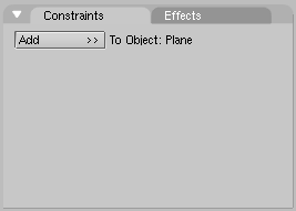
Buttons Window will present a Constraints Panel
(Figure 16.17, “Constraints Panel.”).
Click on the Add
button. A menu of possible constraints will appear.
Once you selected the desired constraint
its buttons will appear. A constraint can be deleted by clicking
on the "X" icon next to it. A constraint can be collapsed
by clicking on its orange triangle icon. When collapsed, a
constraint can be moved up or down in the constraint list by
clicking on it at choosing Move Up
or Move Down from
the popup menu.
For most constraints, a target must be specified in the appropriate field. In this field you must type in the name of the desired target object. If the desired target is a bone, first type in the name of the bone's armature. Another text box will appear allowing you to specify the name of the bone.
Several Constraints are possible. All apply to Bones, some also apply to other Objects:
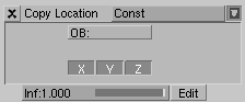
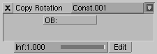
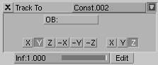
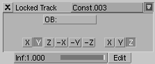
Copy Location- The constraint forces the Object to have an one or more co-ordinates (chosen via the three Toggle Buttons) of its location equal to those of the target (Figure 16.18, “Copy Location Constraint.”).Copy Rotation- This constraint copies the global rotation of the target and applies it to the constraint owner (Figure 16.19, “Copy Rotation Constraint.”).Track To- This constraint causes the constraint owner to point one of its axes (by default the Y-axis) towards the target either in its positive or negative direction, depending on the selected Radio Buttons. The Object rotation will be computed so that another one of its axis (by default the Z-axis) will point up, again this can be changed via the pertinent Radio Buttons. (Figure 16.20, “Track To Constraint.”).Locked Track- This constraint causes the constraint owner to point one of its axes (by default the Y-axis) to point towards the target either in its positive or negative direction, depending on the selected Radio Buttons. The Object rotation will be computed so that another one of its axis (by default the Z-axis) direction is fixed, again this can be changed via the pertinent Radio Buttons.Actually this means that the Object is rotated around it fixed axis so that the Target lies on the plane defined by the locked axis and the pointing axis. (Figure 16.21, “Lock Track.”).
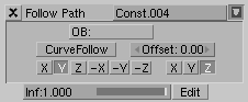
Follow Path- This constraint needs the Target to be a Curve or Path. It causes the constraint owner to follow the path in time.By default the Object translates along the curve in 100 frames. You can make the Object orientation follow the curve with the
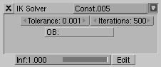
CurveFollowToggle Button and by setting the Radio Buttons below to define which axis should be tangent to the curve and which should point up. To change the number of frames in which the Path is followed you need to edit the Curve's Speed IPO. (Figure 16.22, “Follow Path.”).IK Solver(Bone Only) - To simplify animation of multi-segmented limbs (such as arms and legs) you can add an IK solver constraint. IK constraints can only be added to bones. Once a target is specified, the solver will attempt to move the root of the constraint-owning bone to the target, by re-orienting the bone's parents (but it will not move the root of the chain). If a solution is not possible, the solver will attempt to get as close as possible. Note that this constraint will override the orientations on any of the IK bone's parents (Figure 16.23, “IK Solver Constraint.”).Note
If the Target of the IK Constraint is another bone of the same Armature, as is highly recommended, you must make sure that this bone, usually denominated IK_Tool, is not the child of any other bone of the IK chain, or weird results will happen.
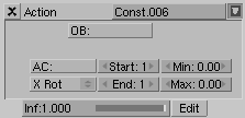
Action(Bone Only) - An Action constraint can be used to apply an Action channel from a different Action to a bone, based on the rotation of another bone or object. The typical way to use this is to make a muscle bone bulge as a joint is rotated. This constraint should be applied to the bone that will actually do the bulging; the target should point to the joint that is being rotated (Figure 16.24, “Action Constraint.”).The AC field contains the name of the Action that contains the flexing animation. The only channel that is required in this Action is the one that contains the bulge animation for the bone that owns this constraint.
The Start and End fields specify the range of motion from the Action.
The Min and Max fields specify the range of rotation from the target bone. The Action between the start and end fields is mapped to this rotation (so if the bone rotation is at the Min point, the Pose specified at Start will be applied to the bone). Note that the Min field may be higher than the Max.
The pulldown menu specifies which component of the rotation is to be considered.
Null- This is a constraint that does nothing at all; it doesn't affect the object's transformation directly. The purpose of a null constraint is to use it as a separator, and why this might be necessary will be clarified in the following section (Figure 16.25, “Null Constraint.”).
Constraints can be applied to objects or bones. In the case of constraints applied to bones, any constraints on the armature object will be evaluated before the constraints on the bones are considered.
When a specific constraint is evaluated, all of its dependencies will have already been evaluated and will be in their final orientation/positions. Examples of dependencies are the object's parent, its parent's parents (if any) and the hierarchies of any targets specified in the constraint.
Within a given object, constraints are executed from top to bottom. Constraints that occur lower in the list may override the effects of constraints higher in the list. Each constraint receives as input the results of the previous constraint. The input to the first constraint in the list is the output of the IPOs associated with the object.
If several constraints of the same type are specified in a
contiguous block, the constraint will be evaluated
once for
the entire block, using an average of all the targets. In
this way you can constrain an object to track to the point
between two other objects, for example. You can use a
Null
constraint to insert a break in a constraint block if you
would prefer each constraint to be evaluated individually.
Looping constraints are not allowed. If a loop is detected, all of the constraints involved will be temporarily disabled (and highlighted in red). Once the conflict has been resolved, the constraints will automatically re-activate.
The influence slider next to each constraint is used to determine how much effect the constraint has on the transformation of the object.
If there is only a single constraint in a block (a block is a series of constraints of the same type which directly follow one another), an influence value of 0.0 means the constraint has no effect on the object. An influence of 1.0 means the constraint has full effect.
If there are several constraints in a block, the influence values are used as ratios. So in this case if there are two constraints, A and B, each with an influence of 0.1, the resulting target will be in the centre of the two target objects (a ratio of 0.1:0.1 or 1:1 or 50% for each target).
Influence can be controlled with an IPO. To add a constraint IPO for a constraint, open an IPO Window and change its type to constraint by clicking on the chain icon. Next click on the Edit IPO Button next to the constraint you wish to work with. If there is no constraint IPO associated with the constraint yet, one will be created. Otherwise the previously assigned IPO will be displayed. At the moment, KeyFrames for constraint IPOs can only be created and edited in the IPO Window, by selecting the INF channel and CTRL-LMB in the IPO space.
When blending Actions with constraint IPOs, note that only the IPOs on the armature's local Action IPOs are considered. Constraint IPOs on the Actions in the motion strips are ignored.
Important
In the case of armatures, the constraints IPOs are stored in the current Action. This means that changing the Action will change the constraint IPOs as well.