Drools already provides some functionality to define the order in which rules should be executed, like salience, activation groups, etc. When dealing with (possibly a lot of) large rule-sets, managing the order in which rules are evaluated might become complex. Ruleflow allows you to specify the order in which rule sets should be evaluated by using a flow chart. This allows you to define which rule sets should be evaluated in sequence or in parallel, to specify conditions under which rule sets should be evaluated, etc. This chapter contains a few ruleflow examples.
A rule flow is a graphical description of a sequence of steps that the rule engine needs to take, where the order is important. The ruleflow can also deal with conditional branching, parallelism, synchonization, etc.
To use a ruleflow to describe the order in which rules should be evaluatied, you should first group rules into rulefow-groups using the ruleflow-group rule attribute ("options" in the GUI). Then you should create a ruleflow graph (which is a flow chart) that graphically describe the order in which the rules should be considered (by specifying the order in which the ruleflow-groups should be evaluated).
  rule 'YourRule'
     ruleflow-group 'group1'
     when
      ...
     then
      ...
    end
This rule will then be placed in the ruleflow-group called "group1".
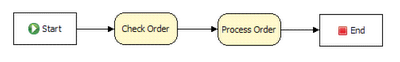
The above rule flow specifies that the rules in the group "Check Order" must be executed before the rules in the group "Process Order". This means that only rules which are marked as having a ruleflow-group of "Check Order" will be considered first, and then "Process Order". That's about it. You could achieve similar results with either using salience (setting priorities, but this is harder to maintain, and makes the time-relationship implicit in the rules), or agenda groups. However, using a ruleflow makes the order of processing explicit, almost like a meta-rule, and makes managing more complex situations a lot easier. The various elements that can be used inside a ruleflow will be explained in more detail later.
Ruleflows can only be created by using the graphical ruleflow editor which is part of the Drools plugin for Eclipse. Once you have set up a Drools project (check the IDE chapter if you do not know how to do this), you can start adding ruleflows. When in a project, use "control+N" to launch the new wizard, or right-click the directory you would like to put your ruleflow in and select "New ... Other ...":
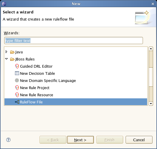
Choose the section on "Drools" and then pick "RuleFlow file". This will create a new .rf file.
Next you will see the graphical ruleflow editor. Now would be a good time to switch to the "Drools perspective" (if you haven't done so already) - this will tweak the UI so it is optimal for rules. Then ensure that you can see the "properties" panel down the bottom of the eclipse window, as it will be necessary to fill in the different properties of the elements in your ruleflow. If you cannot see the properties view, open it using the Menu Window - Show View - Other ..., and under the General folder select the Properties view.
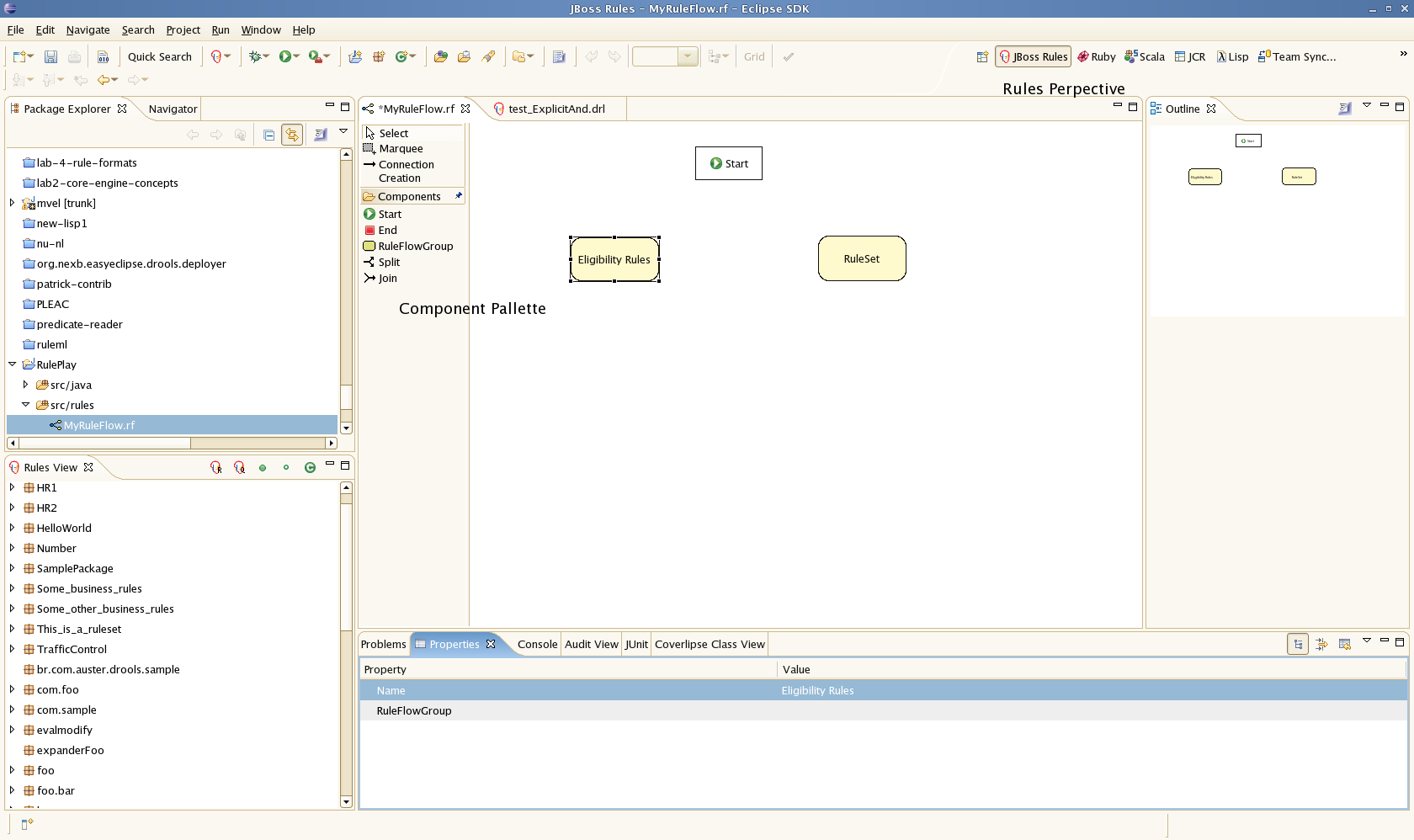
The RuleFlow editor consists of a palette, a canvas and an outline view. To add new elements to the canvas, select the element you would like to create in the palette and then add them to the canvas by clicking on the preferred location. For example, click on the RuleFlowGroup icon in the Component Pallette of the GUI - you can then draw a few rule flow groups. Clicking on an element in your ruleflow allows you to set the properties of that element.
Click on a ruleflow group, and you should see the following:
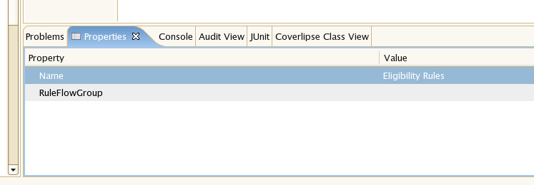
You can see here you set the visible name, but you also need to set the actual group name that is used in the rules.
Next step is to join the groups together (if its a simple sequence of steps) - you use this by using "create connection" from the component palette. You should also create an "End" node (also from the component palette).
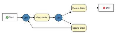
In practice, if you are using ruleflow, you will most likely be doing more then setting a simple sequence of groups to progress though. You are more likely modeling branches of processing. In this case you use "Split" and "Join" items from the component pallette. You use connections to connect from the start to ruleflow groups, or to Splits, and from splits to groups, joins etc. (i.e. basically like a simple flow chart that models your processing). You can work entirely graphically until you get the graph approximately right.
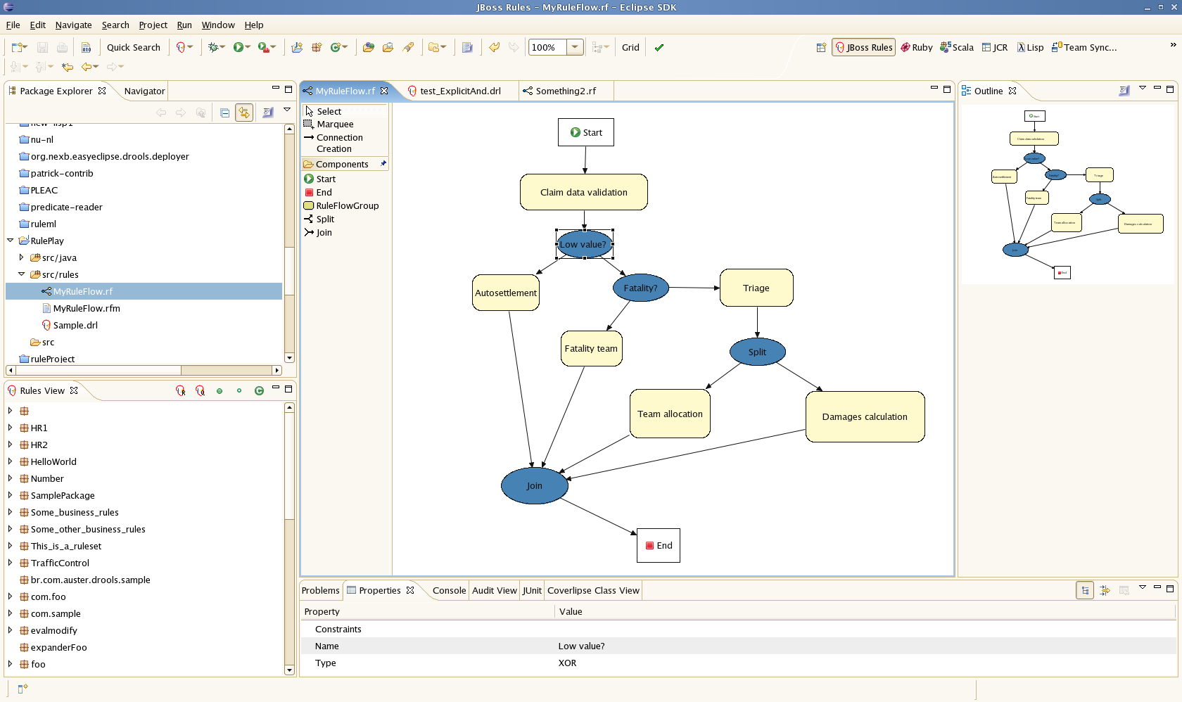
The above flow is a more complex example. This example is an insurance claim processing rule flow. A description: Initially the claim data validation rules are processed (these check for data integrity and consistency, that all the information is there). Next there is a decision "split" - based on a condition which the rule flow checks (the value of the claim), it will either move on to an "auto-settlement" group, or to another "split", which checks if there was a fatality in the claim. If there was a fatality then it determines if the "regular" of fatality specific rules will take effect. And so on. What you can see from this is based on a few conditions in the rule flow the steps that the processing takes can be very different. Note that all the rules can be in one package - making maintenance easy. You can separate out the flow control from the actual rules.
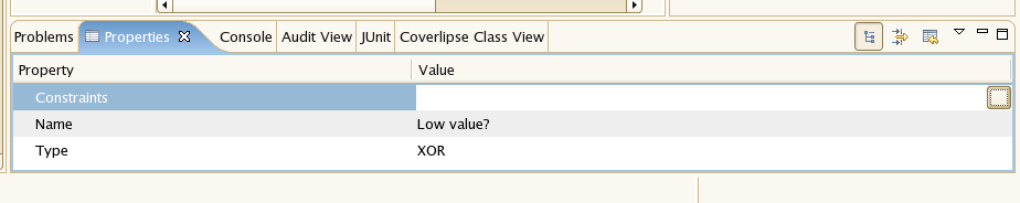
Split types (referring to the above): When you click on a split, you will see the above properties panel. You then have to choose the type: AND, OR, and XOR. The interesting ones are OR and XOR: if you choose OR, then any of the "outputs" of the split can happen (ie processing can proceed in parallel down more then one path). If you chose XOR, then it will be only one path.
If you choose OR or XOR, then in the row that has constraints, you will see a button on the right hand side that has "..." - click on this, and you will see the constraint editor. From this constraint editor, you set the conditions which the split will use to decide which "output path" will be chosen.
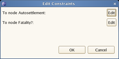
Choose the output path you want to set the constraints for (eg Autosettlement), and then you should see the following constraint editor:
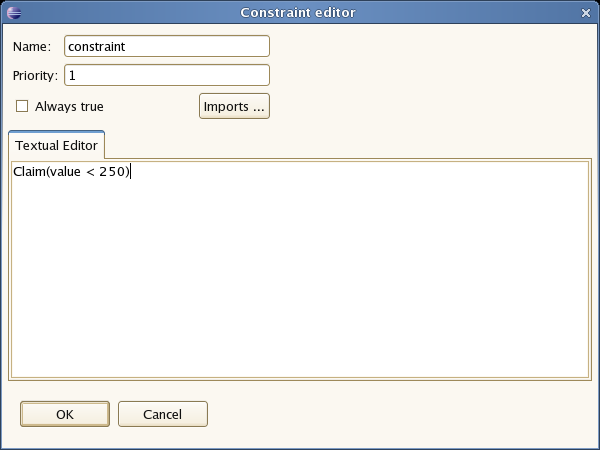
This is a text editor where the constraints (which are like the condition part of a rule) are entered. These constraints operate on facts in the working memory (eg. in the above example, it is checking for claims with a value of less than 250). Should this condition be true, then the path specified by it will be followed.
Once you have a valid ruleflow (you can check its valid by pressing the green "tick" icon in the IDE), you can add a rule flow to a package just like a drl. However, the IDE creates two versions of your ruleflow: one containing the ruleflow definition (*.rfm) and one containing additional graphical information (*.rf). When adding a ruleflow to a package, you should make sure that you are adding the .rfm file to your ruleflow (and not the .rf file).
Reader rfm = ... (rule flow reader, select your .RFM file here)
packageBuilder.addRuleFlow(rfm);
Alternatively, you can upload the .rf file to the BRMS (as a ruleflow asset) and it will automatically be included in packages that are deployed from it.
Ruleflows are only executed if you explicitly state that they should be executed. This is because you could potentially define a lot of ruleflows in your package and the engine has no way to know when you would like to start each of these. To activate a particular ruleflow, you will need to start the process by calling the startProcess method on the working memory. For example, if you want to start a particular workflow after you have asserted your facts into the working memory, use:
workingMemory.startProcess("ID_From_your_Ruleflow_properties");(The ruleflow id can be specified in the properties view when you click the background canvas of your ruleflow). And then call fireAllRules(). This will start executing rules, taking the order specified in the ruleflow into account. Thats it !
You can also start a ruleflow process from within a rule consequence using
drools.getWorkingMemory().startProcess("ID_From_your_Ruleflow_properties");
A ruleflow is a flow chart where different types of nodes are linked using connections. It has the following properties: a (unique) id, a (display) name and a version. You can also specify how the connections are visualized on the canvas using the connection layout property:
manual always draws your connections as lines going straight from their start to end point (with the possibility to use intermediate break points)
shortest path is similar, but it tries to go around any obstacles is might encounter between the start and end point (to avoid lines crossing nodes)
manhatten draws connections by only using horizontal and vertical lines
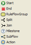
Currently, ruleflow supports eight types of nodes:
Start: the start of the ruleflow. A ruleflow should have exactly one start node. The start node cannot have incoming cnnections and should have one outgoing connection. It contains one property "name" which is the display name of the node. Whenever ruleflow process is started, the ruleflow will start executing here and automatically continue to the first node linked to this start node
End: the end of the ruleflow. A ruleflow should have one or more end nodes. The end node should have one incoming connection and cannot have outgoing connections. It contains one property "name" which is the display name of the node. When an end node is reached in the ruleflow, the ruleflow is terminated (including other remaining active nodes when parallelism is used).
RuleFlowGroup: represents a set of rules. A RuleFlowGroup node should have one incoming connection and one outgoing connection. It contains a property "name" which is the display name of the node, and the property ruleflow-group which is used to specify the name of the ruleflow-group that represents the set of rules of this RuleFlowGroup node. When a RuleFlowGroup node is reached in the ruleflow, the engine will start executing rules that are part of the corresponding ruleflow-group. Execution will automatically continue to the next node if there are no more active rules in this ruleflow-group. This means that, during the execution of a ruleflow-group, it is possible that new activations belonging to the currently active ruleflow-group are added to the agenda due to changes made to the facts by the other rules. Note that the ruleflow will immediately continue with the next node if it encounters a ruleflow-group where there are no active rules at that point.
Split: allows you to create branches in your ruleflow. A split node should have one incoming connection and two or more outgoing connections. It contains a property "name" which is the display name of the node. There are three types of splits currently supported:
AND means that the control flow will continue in all outgoing connections simultaneously
XOR means that exactly one of the outgoing connections will be chosen. Connections are chosen by evaluating the constraints that are linked to each of the outgoing connections. Constraints are specified using the same syntax as the left-had side of a rule. The constraint with the lowest priority number that evaluates to true is selected. Note that you should make sure that at least one of the outgoing connections will evaluate to true at runtime, or the ruleflow will throw an exception at runtime if it cannot find an outgoing connection. For example, you could use a connection which is always true with a high priority number to specify what should happen if none of the other connections can be taken.
OR means that all outgoing connections whose condition evaluates to true are selected. Conditions are similar to the XOR split, except that the priorities are not taken into account. Note that you should make sure that at least one of the outgoing connections will evaluate to true at runtime, or the ruleflow will throw an exception at runtime if it cannot find an outgoing connection.
Join: allows you to synchronize multiple branches. A join node should have two or more incoming connections and one outgoing connection. It contains a property "name" which is the display name of the node. There are two types of splits currently supported:
AND means that is will wait until all incoming branches are completed before continuing
XOR means that it continues if one of its incoming branches has been completed
Milestone: represents a wait state. A milestone should have one incoming connection and one outgoing connection. It contains a property "name" which is the display name of the node, and the property "constraint" which specifies how long the ruleflow should wait in this state before continuing. For example, a milestone constraint in an order entry application might specify that the ruleflow should wait until (a fact in the working memory specifies that) no more errors are found in the given order. Constraints are specified using the same syntax as the left-had side of a rule. When a Milestone node is reached in the ruleflow, the engine will check the associated constraint. If the constraint evaluates to true directly, the flow will continue imediately. Otherwise, the flow will continue if the constraint is satisfied later on, for example when a facts in the working memory is inserted, updated or removed.
Subflow: represents the invocation of another ruleflow from withing this ruleflow. A subflow node should have one incoming connection and one outgoing connection. It contains a property "name" which is the display name of the node, and the property "processId" which specifies the id of the process that should be executed. When a Subflow node is reached in the ruleflow, the engine will start the process with the given id. The subflow node will only continue if that subflow process has terminated its execution. Note that the subflow process is started as an independent process, which means that the subflow process will not be terminated if this process reaches an end node.
Action: represents an action that should be executed in this ruleflow. An action node should have one incoming connection and one outgoing connection. It contains a property "name" which is the display name of the node, and the property "action" which specifies the action that should be executed. When an action node is reached in the ruleflow, it will execute the action and continue with the next node. An action should be specified as a piece of (valid) MVEL code.