The Interconnect
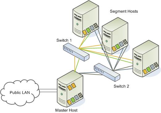
The interconnect is the networking layer of Greenplum Database. When a user connects to a database and issues a query, processes are created on each of the segments to handle the work of that query. The interconnect refers to the inter-process communication between the segments, as well as the network infrastructure on which this communication relies. The interconnect uses a standard 10 Gigabit Ethernet switching fabric.
By default, the interconnect uses UDP (User Datagram Protocol) to send messages over the network. The Greenplum software does the additional packet verification and checking not performed by UDP, so the reliability is equivalent to TCP (Transmission Control Protocol), and the performance and scalability exceeds that of TCP.
Interconnect Redundancy
A highly available interconnect can be achieved by deploying dual 10 Gigabit Ethernet switches on your network, and redundant 10 Gigabit connections to the Greenplum Database master and segment host servers.
Network Interface Configuration
A segment host typically has multiple network interfaces designated to Greenplum interconnect traffic. The master host typically has additional external network interfaces in addition to the interfaces used for interconnect traffic.
Depending on the number of interfaces available, you will want to distribute interconnect network traffic across the number of available interfaces. This is done by assigning segment instances to a particular network interface and ensuring that the primary segments are evenly balanced over the number of available interfaces.
This is done by creating separate host address names for each network interface. For example, if a host has four network interfaces, then it would have four corresponding host addresses, each of which maps to one or more primary segment instances. The /etc/hosts file should be configured to contain not only the host name of each machine, but also all interface host addresses for all of the Greenplum Database hosts (master, standby master, segments, and ETL hosts).
With this configuration, the operating system automatically selects the best path to the destination. Greenplum Database automatically balances the network destinations to maximize parallelism.
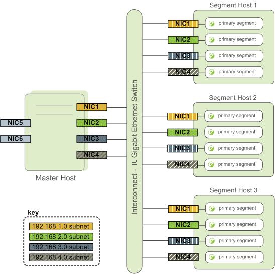
Switch Configuration
When using multiple 10 Gigabit Ethernet switches within your Greenplum Database array, evenly divide the number of subnets between each switch. In this example configuration, if we had two switches, NICs 1 and 2 on each host would use switch 1 and NICs 3 and 4 on each host would use switch 2. For the master host, the host name bound to NIC 1 (and therefore using switch 1) is the effective master host name for the array. Therefore, if deploying a warm standby master for redundancy purposes, the standby master should map to a NIC that uses a different switch than the primary master.