
IMS General Web Services WSDL Binding Guidelines
Version 1.0 Final Specification
 |
IMS General Web Services WSDL Binding Guidelines Version 1.0 Final Specification |
Copyright © 2005 IMS Global Learning
Consortium, Inc. All Rights Reserved.
The IMS Logo is a registered trademark of IMS/GLC
Document Name: IMS General Web Services WSDL Binding
Guidelines
Revision: 19 December 2005
IPR and Distribution Notices
Recipients of this document are requested to submit, with their comments, notification of any relevant patent claims or other intellectual property rights of which they may be aware that might be infringed by any implementation of the specification set forth in this document, and to provide supporting documentation.
IMS takes no position regarding the validity or scope of any intellectual property or other rights that might be claimed to pertain to the implementation or use of the technology described in this document or the extent to which any license under such rights might or might not be available; neither does it represent that it has made any effort to identify any such rights. Information on IMS's procedures with respect to rights in IMS specifications can be found at the IMS Intellectual Property Rights web page: http://www.imsglobal.org/ipr/imsipr_policyFinal.pdf.
Copyright © 2005 IMS Global Learning Consortium. All Rights Reserved.
If you wish to copy or distribute this document, you must complete a valid Registered User license registration with IMS and receive an email from IMS granting the license to distribute the specification. To register, follow the instructions on the IMS website: http://www.imsglobal.org/specificationdownload.cfm.
This document may be copied and furnished to others by Registered Users who have registered on the IMS website provided that the above copyright notice and this paragraph are included on all such copies. However, this document itself may not be modified in any way, such as by removing the copyright notice or references to IMS, except as needed for the purpose of developing IMS specifications, under the auspices of a chartered IMS project group.
Use of this specification to develop products or services is governed by the license with IMS found on the IMS website: http://www.imsglobal.org/license.html.
The limited permissions granted above are perpetual and will not be revoked by IMS or its successors or assigns.
THIS SPECIFICATION IS BEING OFFERED WITHOUT ANY WARRANTY WHATSOEVER, AND IN PARTICULAR, ANY WARRANTY OF NONINFRINGEMENT IS EXPRESSLY DISCLAIMED. ANY USE OF THIS SPECIFICATION SHALL BE MADE ENTIRELY AT THE IMPLEMENTER'S OWN RISK, AND NEITHER THE CONSORTIUM, NOR ANY OF ITS MEMBERS OR SUBMITTERS, SHALL HAVE ANY LIABILITY WHATSOEVER TO ANY IMPLEMENTER OR THIRD PARTY FOR ANY DAMAGES OF ANY NATURE WHATSOEVER, DIRECTLY OR INDIRECTLY, ARISING FROM THE USE OF THIS SPECIFICATION.
The 'IMS General Web Services WSDL Binding Guideline' document outlines a process for creating web service bindings using the IMS General Web Services Base Profile, Abstract Framework and business domain knowledge intrinsic to the Information Model of a particular Specification. The 'General Web Services WSDL Binding Guideline' contains a description of how a project teams should use the Unified Modelling Language (UML) and Extensible Mark-up Language (XML) style-sheet language auto-generation tools to specify a Web Service protocol and binding as appropriate.
For the auto-generation approach to work the IMS specification must be represented with UML. IMS has created a Web Services description Profile that defines how UML is to be used to describe a web service-based specification. A specification becomes a collection of UML packages. UML packages are used to ensure that the different ways in which UML models are visually presented by different UML tools do not result in tool interoperability issues. Three types of package stereotypes are used:
The IMS General Web Services Basic Profile introduced the approach of separate bindings for different communications models. Therefore, three sets of transformation rules are required, one for each of the communication models that are to be supported by the bindings, namely (at the current time only the Synchronous binding is described herein):
This Guideline contains a description of how the IMS Binding Auto-generation Tool-kit (I-BAT) is used to create the WSDL/XSD files from the XMI-based description of the specification. The I-BAT is used to create WSDL/XSD bindings that are categorized as:
The WSDL/XSD files created are designed to comply with the Web Service Interoperability (WS-I) Consortium Base Profile v1.1. A clear statement of the relationship between the WS-I Base Profile and the IMS General Web Service Basic Profile is described in the IMS GWS Base Profile V1.0 Specification. Furthermore information on how the equivalent WSDL/XSD bindings are created to support the IMS General Web Services extension profiles, e.g., Addressing, Security, Attachments, etc. are supplied in the corresponding profile specifications. This guideline also presents recommendations on how to extend the specification by changing the UML description and re-applying the auto-generation file, and the areas for further work.
The objective of the General Web Services Web Services Description Language (WSDL) Binding Guidelines activity is to provide a framework for guiding project teams looking to use web services as part of IMS/GLC specification development. The General Web Services WSDL Binding Guidelines provide a methodology that meets the following criteria:
The General Web Services WSDL Binding Guidelines (GWSWBG) outlines a process for creating web service bindings using the IMS General Web Services Base Profile, IMS Abstract Framework and business knowledge intrinsic to the Information Model of a particular Specification. The GWSWBG includes guidelines that instruct project groups in how to use the recommended tools in gathering information, processing information, and specifying Web Services protocols and binding as appropriate. The methodology includes information and graphics describing the role and relationship of the General Web Services methodology to the IMS/GLC Specifications. The creation of the WSDL binding files is based upon representation of the specification in the UML. The XML Metadata Interchange (XMI) representation of UML is then used to enable the auto-generation. The automated conversion is supplied by applying one or more specially developed Extensible Stylesheet Language Transformations (XSLTs) to the XMI to create the corresponding set of WSDL and Extensible Schema Definition (XSD) files.
This document should be read in conjunction with the General Web Services Base Profile document [GWS, 05b] and the set if extension profiles [GWS, 05c], [GWS, 05d] and [GWS, 05d] and the IMS Binding Auto-generation Toolkit (I-BAT) Manual [GWS, 05e]. The terms of reference for the creation of both documents are defined in the original project charter [GWS, 03].
The structure of this document is:
| [AbsASCs,
03] |
IMS
Abstract Framework: Applications, Services & Components
v1.0, Ed. C.Smythe, IMS/GLC, July
2003. |
| [AbsGloss, 03] |
IMS
Abstract Framework: Glossary v1.0, Ed. C.Smythe,
IMS/GLC, July 2003. |
| [AbsWhite, 03] |
IMS
Abstract Framework: White Paper v1.0, Ed. C.Smythe,
IMS/GLC, July 2003. |
| [APG,
04a] |
IMS
Application Profile Guidelines Whitepaper: Part 1 Management
Overview, K.Riley and P.Hope, Version 1.0, IMS
Publication, May 2004. |
| [APG,
04b] |
IMS
Application Profile Guidelines Whitepaper: Part 2 Technical
Manual, K.Riley and P.Hope, Version 1.0, IMS
Publication, May 2004. |
| [Cockburn, 01] |
Writing Effective Use-case,
A.Cockburn, Addison-Wesley, 2001, ISBN
0-201-70225-8. |
| [GWS,
03] |
General Web Services Project Team
Charter, C.Schroeder, R.Kleinman and S.Griffin,
IMS/GLC, June 2003. |
| [GWS,
05a] |
IMS
General Web Services UML to WSDL Binding Auto-generation
Guidelines Public Draft, C.Schroeder, S.Raju and C.Smythe,
V1.0 IMS/GLC, January 2005. |
| [GWS,
05b] |
IMS
General Web Services Base Profile Final Release,
C.Schroeder, J.Simon and C.Smythe, V1.0 IMS/GLC,
December 2005. |
| [GWS,
05c] |
IMS
General Web Services Addressing Profile Final Release,
C.Schroeder, J.Simon and C.Smythe, V1.0 IMS/GLC,
December 2005. |
| [GWS,
05d] |
IMS
General Web Services Attachments Profile Final Release,
C.Schroeder, J.Simon and C.Smythe, V1.0 IMS/GLC,
December 2005. |
| [GWS,
05e] |
IMS
General Web Services Security Profile Final Release,
C.Schroeder, J.Simon and C.Smythe, V1.0 IMS/GLC,
December 2005. |
| [GWS,
05f] |
IMS
Binding Auto-generation Toolkit Manual, C.Smythe, V1.0
IMS/GLC, December 2005. |
| [SOAP,
01a] |
SOAP Messages with Attachments,
W3C, W3C Note 11, December 2000. |
| [SOAP,
03a] |
SOAP Version 1.2 Part 1: Messaging
Framework, W3C, W3C Final Specification, June
2003. |
| [SOAP,
03b] |
SOAP Version 1.2 Part 2: Adjuncts,
W3C, W3C Final Specification, June 2003. |
| [SpecDev,
03] |
IMS
Specification Development Methods & Best Practices
v1.0, C.Smythe, IMS/GLC, Sept. 2003. |
| [UML,
04] |
The
Unified Modeling Language Reference Manual, J.Rumbaugh,
I.Jacobson and G.Booch, 2nd Ed,
Addison-Wesley, ISBN 0-321-24562-8. |
| [WSDL,
01] |
Web
Services Description Language, http://www.w3.org/TR/2001/NOTE-wsdl-20010315,
Version 1.1, W3C, W3C Note, March 2001. |
| [WSDL,
04] |
Web
Services Description Language, Version 2.0,
W3C, W3C Working Draft 3, August 2004. |
| [WSI,
03] |
Web
Services Interoperability Basic Profile Version 1.0, Eds
K.Ballinger, D.Ehnebuske, M.Gudgin, M.Nottingham and P.Yendluri
Web Services-Interoperability Organization, June
2003. |
| [WSI,
04a] |
Web
Services Interoperability Basic Profile Version 1.1, Eds
K.Ballinger, D.Ehnebuske, C.Ferris, M.Gudgin, C.K.Liu,
M.Nottingham and P.Yendluri, Web Services-Interoperability
Organization, August 2004. |
| [WSI,
04b] |
WS-I Attachments Profile Version 1.0,
Eds C.Ferris, A.Karmarkar and C.K.Liu, Web
Services-Interoperability Organization, August
2004. |
| [WSI,
04c] |
WS-I Conformance Claim Attachment Mechanisms
Version 1.0, Eds M.Nottingham and C. von Riegen, Web
Services-Interoperability Organization, November
2004. |
| [WSI,
04d] |
WS-I Simple SOAP Binding Profile Version
1.1, Ed M.Nottingham, Web Services-Interoperability
Organization, August 2004. |
The structure of a WSDLv1.11 document is shown in Figure 2.1.
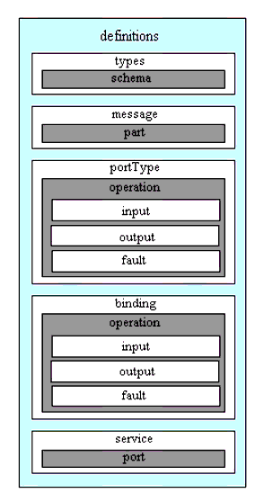
A WSDL document defines services as collections of network endpoints, or ports. In WSDL, the abstract definition of endpoints and messages is separated from their concrete network deployment or data format bindings. This allows the reuse of abstract definitions: messages, which are abstract descriptions of the data being exchanged, and port types that are abstract collections of operations. The concrete protocol and data format specifications for a particular port type constitute a reusable binding. A port is defined by associating a network address with a reusable binding and a collection of ports defines a service. Hence, a WSDL document uses the following elements in the definition of network services:
It should be noted that WSDLv1.1 supports the following simple message choreographies:
More complex choreographies have to be constructed using multiple WSDL file-sets with the choreography between the file-sets imposed by an implementation.
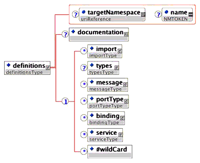
The top level XSD for the WSDL schema is shown in Figure 2.2.
There are three approaches to the creation of the WSDL description:
The <import> schema structure is shown in Figure 2.3. The <import> is used to enable a WSDL description to be defined in several linked physical files. IMS will use the <import> element to link the abstract definition file to the specific service file, i.e., the specific service file imports the abstract definitions file.

The <type> schema structure is shown in Figure 2.4. The <type> Element is used within the single WSDL or abstract definitions file to link to the associated XSD files. These XSD files will contain the XML definitions of the SOAP structures.

The <message> schema structure is shown in Figure 2.5. This element is used within the single WSDL or the abstract definitions file to define the set of messages that are used to exchange the information for a particular operation. The <part> elements are used to define the message header and body parts.

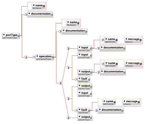
The <portType> schema structure is shown in Figure 2.6. The <portType> element is used within the abstract definitions file to identify the messages used to represent an operation. In a single abstract definition structure an operation can have at most one input message (from the client to the server) and one output message (from the server to the client).
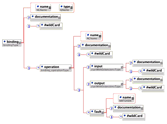
The <binding> schema structure is shown in Figure 2.7. The <binding> element is used within the single WSDL or the specific service file to bind the abstract message definitions to a particular transport mechanism. In the case of the IMS GWS the transport system is SOAPv1.1/HTTPv1.1; no other bindings are supported.
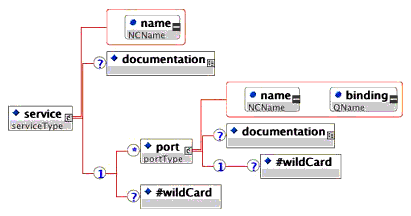
The <service> element is used within the single WSDL or the specific service file to represent a collection of port elements, where each port represents the availability of binding at a particular endpoint. The 'binding' attribute of the port element ties it to the corresponding binding element (see sub-section 2.2.6).
This is a single file containing the WSDL and XSD information. The basic structure of an integrated WSDL document is:
0001 0002 0003 0004 0005 0006 0007 0008 0009 0010 0011 0012 0013 0014 0015 0016 0017 0018 0019 0020 0021 0022 0023 0024 0025 0026 0027 0028 0029 0030 0031 0032 0033 0034 0035 0036 0037 0038 0039 0040 0042 0043 0044 0045 0046 0047 0048 0049 0050 0051 0052 0053 0054 0055 0056 0057 0058 |
<?xml version = "1.0" encoding = "UTF-8"?>
<wsdl:definitions name = "??" targetNamespace = "??">
   <wsdl:types>
      <xsd:schema>
         ...
      </xsd:schema>
   </wsdl:types>
   <wsdl:message name = "??">
      <wsdl:part name = "??" element = "??"/>
   </wsdl:message>
   ...
   <wsdl:message name = "??">
      <wsdl:part name = "??" element = "??"/>
   </wsdl:message>
   <wsdl:portType name = "??">
      <wsdl:operation name = "??">
         <wsdl:input message = "??"/>
         <wsdl:output message = "??"/>
         <wsdl:fault message = "??" name = "??"/>
      </wsdl:operation>
      ...
      <wsdl:operation name = "??">
         <wsdl:input message = "??"/>
         <wsdl:output message = "??"/>
         <wsdl:fault message = "??" name = "??"/>
      </wsdl:operation>
   </wsdl:portType>
   ...
   <wsdl:portType name = "??">
      ...
   </wsdl:portType>
   <wsdl:binding name = "??" type= "??">
      <wsdl:operation name = "??">
         <wsdl:input/>
         <wsdl:output/>
         <wsdl:fault name = "??"/>
      </wsdl:operation>
      <wsdl:operation name = "??">
         <wsdl:input/>
         <wsdl:output/>
         <wsdl:fault name = "??"/>
      </wsdl:operation>
   </wsdl:binding>
   ...
   <wsdl:binding name = "??" type= "??">
      ...
   </wsdl:binding>
   <wsdl:service name = "??">
      <wsdl:port name="??" binding= "??"/>
         ...
      <wsdl:port name="??" binding= "??"/>
   </wsdl:service>
   ...
   <wsdl:service name = "??">
      ...
   </wsdl:service>
</wsdl:definitions>
|
This is the separation of the WSDL and XSD into two separate files. The basic structure of the WSDL document is:
0001 0002 0003 0004 0005 0006 0007 0008 0009 0010 0011 0012 0013 0014 0015 0016 0017 0018 0019 0020 0021 0022 0023 0024 0025 0026 0027 0028 0029 0030 0031 0032 0033 0034 0035 0036 0037 0038 0039 0040 0042 0043 0044 0045 0046 0047 0048 0049 0050 0051 0052 0053 0054 0055 0056 0057 0058 |
<?xml version = "1.0" encoding = "UTF-8"?> <wsdl:definitions name = "??" targetNamespace = "??"> <wsdl:types> <xsd:schema> <xsd:import namespace = "??" schemaLocation = "??"/> </xsd:schema> </wsdl:types> <wsdl:message name = "??"> <wsdl:part name = "??" element = "??"/> </wsdl:message> ... <wsdl:message name = "??"> <wsdl:part name = "??" element = "??"/> </wsdl:message> <wsdl:portType name = "??"> <wsdl:operation name = "??"> <wsdl:input message = "??"/> <wsdl:output message = "??"/> <wsdl:fault message = "??" name = "??"/> </wsdl:operation> ... <wsdl:operation name = "??"> <wsdl:input message = "??"/> <wsdl:output message = "??"/> <wsdl:fault message = "??" name = "??"/> </wsdl:operation> </wsdl:portType> ... <wsdl:portType name = "??"> ... </wsdl:portType> <wsdl:binding name = "??" type= "??"> <wsdl:operation name = "??"> <wsdl:input/> <wsdl:output/> <wsdl:fault name = "??"/> </wsdl:operation> <wsdl:operation name = "??"> <wsdl:input/> <wsdl:output/> <wsdl:fault name = "??"/> </wsdl:operation> </wsdl:binding> ... <wsdl:binding name = "??" type= "??"> ... </wsdl:binding> <wsdl:service name = "??"> <wsdl:port name="??" binding= "??"/> ... <wsdl:port name="??" binding= "??"/> </wsdl:service> ... <wsdl:service name = "??"> ... </wsdl:service> </wsdl:definitions> |
The associated XSD file structure that is linked using the <xsd:import> statement (line 5 - in the shaded region) in the WSDL file is:
0001 0002 0003 0004 |
<?xml version = "1.0" encoding = "UTF-8"?> <xsd:schema> ... </xsd:schema> |
This is the separation of the WSDL into two files (abstract definitions and service specific files) and the XSD as a single file. For the IMS GWS the recommended composition for the Abstract Definitions File is:
0001 0002 0003 0004 0005 0006 0007 0008 0009 0010 0011 0012 0013 0014 0015 0016 0017 0018 0019 0020 0021 0022 0023 0024 0025 0026 0027 0028 0029 0030 0031 0032 |
<?xml version = "1.0" encoding = "UTF-8"?> <wsdl:definitions name = "??" targetNamespace = "??"> <wsdl:types> <xsd:schema> <xsd:import namespace = "??" schemaLocation = "??"/> </xsd:schema> </wsdl:types> <wsdl:message name = "??"> <wsdl:part name = "??" element = "??"/> </wsdl:message> ... <wsdl:message name = "??"> <wsdl:part name = "??" element = "??"/> </wsdl:message> <wsdl:portType name = "??"> <wsdl:operation name = "??"> <wsdl:input message = "??"/> <wsdl:output message = "??"/> <wsdl:fault message = "??" name = "??"/> </wsdl:operation> ... <wsdl:operation name = "??"> <wsdl:input message = "??"/> <wsdl:output message = "??"/> <wsdl:fault message = "??" name = "??"/> </wsdl:operation> </wsdl:portType> ... <wsdl:portType name = "??"> ... </wsdl:portType> </wsdl:definitions> |
For the IMS GWS the recommended composition for the Specific Service File is (the link to the abstract definitions file is achieved using the '<wsdl:import> statement in line 3 - see the shaded region):
0001
0002
0003
0004
0005
0006
0007
0008
0009
0010
0011
0012
0013
0014
0015
0016
0017
0018
0019
0020
0021
0022
0023
0024
0025
0026
0027
0028
0029
|
<?xml version = "1.0" encoding = "UTF-8"?>
<wsdl:definitions name = "??" targetNamespace = "??">
   <wsdl:import namespace = "??" location = "??"/>
   <wsdl:binding name = "??" type= "??">
      <wsdl:operation name = "??">
         <wsdl:input/>
         <wsdl:output/>
         <wsdl:fault name = "??"/>
      </wsdl:operation>
      <wsdl:operation name = "??">
         <wsdl:input/>
         <wsdl:output/>
         <wsdl:fault name = "??"/>
      </wsdl:operation>
   </wsdl:binding>
   ...
   <wsdl:binding name = "??" type= "??">
      ...
   </wsdl:binding>
   <wsdl:service name = "??">
      <wsdl:port name="??" binding= "??"/>
         ...
      <wsdl:port name="??" binding= "??"/>
   </wsdl:service>
   ...
   <wsdl:service name = "??">
      ...
   </wsdl:service>
</wsdl:definitions>
|
Each of the associated XSD file structures that are linked using the <xsd:import> statement (lines 5 to 7 - see the shaded region) in the abstract data definitions WSDL file have the structure:
0001 0002 0003 0004 |
<?xml version = "1.0" encoding = "UTF-8"?> <xsd:schema> ... </xsd:schema> |
This is the separation of the WSDL into two files (abstract definitions and service specific files) and one or more XSD files as required. For the IMS GWS the recommended composition for the Abstract Definitions File is:
0001 0002 0003 0004 0005 0006 0007 0008 0009 0010 0011 0012 0013 0014 0015 0016 0017 0018 0019 0020 0021 0022 0023 0024 0025 0026 0027 0028 0029 0030 0031 0032 0033 0034 |
<?xml version = "1.0" encoding = "UTF-8"?> <wsdl:definitions name = "??" targetNamespace = "??"> <wsdl:types> <xsd:schema> <xsd:import namespace = "??" schemaLocation = "??"/> ... <xsd:import namespace = "??" schemaLocation = "??"/> </xsd:schema> </wsdl:types> <wsdl:message name = "??"> <wsdl:part name = "??" element = "??"/> </wsdl:message> ... <wsdl:message name = "??"> <wsdl:part name = "??" element = "??"/> </wsdl:message> <wsdl:portType name = "??"> <wsdl:operation name = "??"> <wsdl:input message = "??"/> <wsdl:output message = "??"/> <wsdl:fault message = "??" name = "??"/> </wsdl:operation> ... <wsdl:operation name = "??"> <wsdl:input message = "??"/> <wsdl:output message = "??"/> <wsdl:fault message = "??" name = "??"/> </wsdl:operation> </wsdl:portType> ... <wsdl:portType name = "??"> ... </wsdl:portType> </wsdl:definitions> |
For the IMS GWS the recommended composition for the Specific Service File is (the link to the abstract definitions file is achieved using the <wsdl:import> statement in line 3 - see the shaded region):
0001
0002
0003
0004
0005
0006
0007
0008
0009
0010
0011
0012
0013
0014
0015
0016
0017
0018
0019
0020
0021
0022
0023
0024
0025
0026
0027
0028
0029
|
<?xml version = "1.0" encoding = "UTF-8"?>
<wsdl:definitions name = "??" targetNamespace = "??">
   <wsdl:import namespace = "??" location = "??"/>
   <wsdl:binding name = "??" type= "??">
      <wsdl:operation name = "??">
         <wsdl:input/>
         <wsdl:output/>
         <wsdl:fault name = "??"/>
      </wsdl:operation>
      <wsdl:operation name = "??">
         <wsdl:input/>
         <wsdl:output/>
         <wsdl:fault name = "??"/>
      </wsdl:operation>
   </wsdl:binding>
   ...
   <wsdl:binding name = "??" type= "??">
      ...
   </wsdl:binding>
   <wsdl:service name = "??">
      <wsdl:port name="??" binding= "??"/>
         ...
      <wsdl:port name="??" binding= "??"/>
   </wsdl:service>
   ...
   <wsdl:service name = "??">
      ...
   </wsdl:service>
</wsdl:definitions>
|
Each of the associated XSD file structures that are linked using the <xsd:import> statement (lines 5 to 7 - see the shaded region) in the abstract data definitions WSDL file have the structure:
0001 0002 0003 0004 |
<?xml version = "1.0" encoding = "UTF-8"?> <xsd:schema> ... </xsd:schema> |
The Types, Message, Operation, Port Type, Binding, Port and Service elements in the set of WSDL files have strict relationships. To make these relationships we propose a naming convention. The default target namespace is allocated a prefix of 'tns:'. The naming conventions introduced here are further refined in Section 5.
Several services can be defined. Each Service will be given a unique name and will have the string 'Service' at the end. An example of the WSDL is:
0001 0002 0003 0004 0005 0006 |
<wsdl:definitions>
   ...
   <wsdl:service name = "PackagingService">
      ...
   </wsdl:service>
</wsdl:definitions>
|
Several ports can be defined for each service. The Port associates a binding with a network address. Ports that are bound to the same Port Type are treated as alternatives, i.e., two ports could be defined for the same Port Type but one port would use a SOAP binding and the other a HTTP-Post binding. Each Port will have a unique name and will have the string 'Port' at the end. The binding identified in the <wsdl:port> declaration must be defined elsewhere in the WSDL using the <wsdl:binding> element. An example of the WSDL is:
0001 0002 0003 0004 0005 0006 0007 0008 0009 0010 0011 0012 0013 0014 |
<wsdl:definitions>
   ...
   <wsdl:service name = "PackagingService">
      <wsdl:port name = "Packaging1SoapPort" binding = "tns:OpSet1SoapBinding">
         ...
      </wsdl:port>
      <wsdl:port name = "Packaging2SoapPort" binding = "tns:OpSet2SoapBinding">
         ...
      </wsdl:port>
      <wsdl:port name = "PackagingPostPort" binding = "tns:OpSet1PostBinding">
         ...
      </wsdl:port>
   </wsdl:service>
</wsdl:definitions>
|
Every Port Type must have at least one binding. The binding defines the concrete protocol and data format for a particular Port Type. Each binding must have a unique name and will have the string 'Binding' at the end. The Port Type identified in the <wsdl:binding> element must be defined elsewhere n the WSDL using the <wsdl:portType> element. An example of the WSDL is:
0001 0002 0003 0004 0005 0006 0007 0008 0009 0010 0011 0012 0013 |
<wsdl:definitions> ... <wsdl:binding name = "OpSet1SoapBinding" type "tns:OpSet1PortType> ... </wsdl:binding> <wsdl:binding name = "OpSet2SoapBinding" type "tns:OpSet2PortType> ... </wsdl:binding> <wsdl:binding name = "OpSet1PostBinding" type "tns:OpSet1PortType> ... </wsdl:binding> ... </wsdl:definitions> |
Note that for every binding name there must be an associated port usage (note the shaded words in the 'Port Definitions' and 'Binding Definitions' examples.
The Port Type is an abstract set of operations supported by one or more end points. Each Port Type must have a unique name and will have the string 'PortType' at the end. An example of the WSDL is:
0001 0002 0003 0004 0005 0006 0007 0008 0009 0010 |
<wsdl:definitions> ... <wsdl:portType name = "OpSet1PortType"> ... </wsdl: portType > <wsdl:portType name = "OpSet2PortType"> ... </wsdl:portType> ... </wsdl:definitions> |
Note that every Port Type must be used in a binding. The relationship between the 'Port Type Definitions' and the 'Binding Definitions' is shown by the underlined phrases in the corresponding examples.
An operation is an abstract description of an action supported by the service. Operations are associated with a Port Type. Each operation within a Port Type must have a unique name and this name should be representative of the functional nature of the operation. An example of the WSDL is:
0001 0002 0003 0004 0005 0006 0007 0008 0009 0010 0011 0012 0013 0014 0015 0016 0017 0018 0019 0020 0021 0022 |
<wsdl:definitions>
   ...
   <wsdl:portType name = "OpSet1PortType">
      <wsdl:operation name = "createObject">
         ...
      </wsdl:operation>
      ...
      <wsdl:operation name = "deleteObject">
         ...
      </wsdl:operation>
   </wsdl: portType >
   <wsdl:portType name = "OpSet2PortType">
      <wsdl:operation name = "compressObjects">
         ...
      </wsdl:operation>
      ...
      <wsdl:operation name = "expandObjects">
         ...
      </wsdl:operation>
   </wsdl:portType>
   ...
</wsdl:definitions>
|
A message is the abstract construct of the information being communicated. Messages are used to communicate the activity of the corresponding operations. The number of messages per operation depends upon the choreography for the service is 'one-way', 'request-response', solicit-response' or 'notification'. For the 'request-response' choreography the naming convention for the two messages is to take the name of the operation and append the string 'Request' for the message to the endpoint and the string 'Response' for the message from the end point. The example WSDL is:
0001 0002 0003 0004 0005 0006 0007 0008 0009 0010 0011 0012 0013 0014 0015 0016 0017 0018 0019 0020 0021 0022 0023 0024 0025 0026 0027 0028 0029 0030 0031 0032 0033 0034 0035 0036 0037 0038 0039 0040 0041 0042 0043 0044 0045 0046 0047 0048 0049 0050 0051 |
<wsdl:definitions> ... <wsdl:message name = "createObjectRequest"> ... </wsdl:message> <wsdl:message name = "createObjectResponse"> ... </message> <wsdl:message name = "deleteObjectRequest"> ... </wsdl:message> <wsdl:message name = "deleteObjectResponse"> ... </wsdl:message> <wsdl:message name = "compressObjectRequest"> ... </wsdl:message> <wsdl:message name = "compressObjectResponse"> ... </wsdl:message> <wsdl:message name = "expandObjectRequest"> ... </wsdl:message> <wsdl:message name = "expandObjectResponse"> ... </wsdl:message> ... <wsdl:portType name = "OpSet1PortType"> <wsdl:operation name = "createObject"> <wsdl:input message = "tns:createObjectRequest"> <wsdl:output message = "tns:createObjectResponse"> </wsdl:operation> ... <wsdl:operation name = "deleteObject"> <wsdl:input message = "tns:deleteObjectRequest"> <wsdl:output message = "tns:deleteObjectResponse"> </wsdl:operation> </wsdl: portType > <wsdl:portType name = "OpSet2PortType"> <wsdl:operation name = "compressObjects"> <wsdl:input message = "tns:compressObjectRequest"> <wsdl:output message = "tns:compressObjectResponse"> </wsdl:operation> ... <wsdl:operation name = "expandObjects"> <wsdl:input message = "tns:expandObjectRequest"> <wsdl:output message = "tns:expandObjectResponse"> </operation> </wsdl:portType> ... </wsdl:definitions> |
Note that the message descriptions are linked to the operation descriptions and every message must be used in at least one operation. In the WSDL example above the naming convention is shown by the shaded and underlined phrases.
The WS-I Basic Profile 1.1 [WSI, 04a] consists of a set of non-proprietary Web services specifications, plus clarifications, refinements, interpretations and amplifications of those specifications which promote interoperability. The Profile was developed according to a set of principles that, together, form the philosophy of the Profile, as it relates to bringing about interoperability. The principles are:
The IMS GWS Base Profile [GWS, 05a] is heavily based upon the WS-I Basic Profile v1.1 [WSI, 04a] and the WS-I simple SOAP binding Profile v1.0 [WSI, 04d]. There are some points where the IMS GWS Base Profile differs from the WS-I equivalent. These differences are identified in Section 3 of [GWS, 05a].
Three sets of transformation rules are required, one for each of the communication models that are to be supported by the bindings. The three communication models are:
The transformation algorithm is used to create the single file WSDL/XSD representation shown in Figure 3.1.
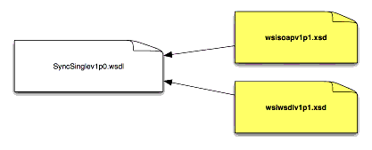
The binding files described in Figure 3.1 contain:
The name space prefixes used within this binding are listed in Table 3.1.
| Namespace | Usage |
|---|---|
| "tns:" |
The
target namespace identifier. |
| "xs:" |
The XML
schema definition namespace. The reference is to: http://www.w3.org/2001/XMLSchema |
| "soap11:" |
The SOAP
references used within the WSDL files. The reference is to: "wsisoapv1p1.xsd". |
| "wsdl11:" |
The
default WSDL files namespace for WSDL v1.1. The reference is to: "wsiwsdlv1p1.xsd". |
The transformation algorithm is used to create the single WSDL and single XSD files representation shown in Figure 3.2.
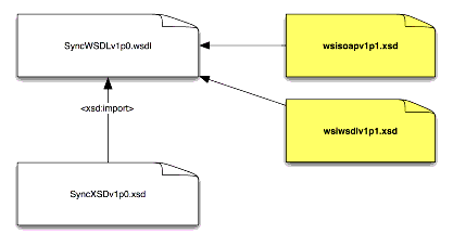
The binding files described in Figure 3.2 contain:
The name space prefixes used within this binding are listed in Table 3.2.
| Namespace | Usage |
|---|---|
| "tns:" |
The
target namespace identifier. |
| "data:" |
The
prefix for importing the XSD into the WSDL file. |
| "xs:" |
The XML
schema definition namespace. The reference is to: http://www.w3.org/2001/XMLSchema |
| "soap11:" |
The SOAP
references used within the WSDL files. The reference is to: "wsisoapv1p1.xsd". |
| "wsdl11:" |
The
default WSDL files namespace for WSDL v1.1. The reference is to: "wsiwsdlv1p1.xsd". |
The transformation algorithm is used to create the service specific and abstract definition WSDL and single XSD files shown in Figure 3.3.
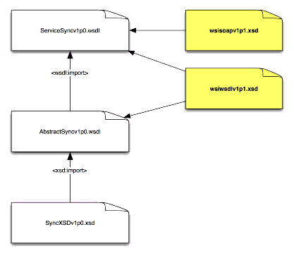
The binding files described in Figure 3.3 contain:
The name space prefixes used within this binding are listed in Table 3.3.
| Namespace | Usage |
|---|---|
| "tns:" |
The
target namespace identifier. |
| "data:" |
The
prefix for importing the XSD into the abstract definitions WSDL
file. |
| "xs:" |
The XML
schema definition namespace. The reference is to: http://www.w3.org/2001/XMLSchema |
| "abs:" |
The
abstract definitions file references. The reference is to: "AbstractSyncv1p0.wsdl" |
| "soap11:" |
The SOAP
references used within the WSDL files. The reference is to: "wsisoapv1p1.xsd". |
| "wsdl11:" |
The
default WSDL files namespace for WSDL v1.1. The reference is to: "wsiwsdlv1p1.xsd". |
The transformation algorithm is used to create the multiple WSDL and XSD files shown in Figure 3.4. The binding files described in Figure 3.4 contain:
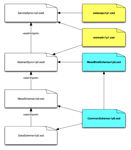
The separation of the 'Service Specific' and 'Abstract Definition' files means that a new Service Specific binding can be created without changing the Abstract Definition. The Abstract Definition describes the behaviors in the UML model whereas the Service Specific file is responsible for binding these to the required transport protocol (in this document this is SOAP/http).
The name space prefixes used within these bindings are listed in Table 3.4.
| Namespace | Usage |
|---|---|
| "tns:" |
The
target namespace identifier. |
| '***:' |
The set
of prefixes that are to be used for the set of XSD data
files. |
| "xs:" |
The XML
schema definition namespace. The reference is to: http://www.w3.org/2001/XMLSchema |
| "msg:" |
The
message structure definition for the service operations. The reference is to "MessSchemav1p0.xsd". |
| "iaf:" |
The IMS
common data model definitions namespace. The reference is to: "CommonSchemav1p0.xsd". |
| "isb:" |
The IMS
message header binding definitions namespace. The reference is to: "MessBindSchemav1p0.xsd". |
| "abs:" |
The
abstract definitions file references. The reference is to: "AbstractSyncv1p0.wsdl" |
| "soap11:" |
The SOAP
references used within the WSDL files. The reference is to: "wsisoapv1p1.xsd". |
| "wsdl11:" |
The
default WSDL files namespace for WSDL v1.1. The reference is to: "wsiwsdlv1p1.xsd". |
At the current time IMS has not authorized the publication of the Asynchronous Communications transformation algorithms as Final Release. This is because there are no validated implementations of this technique and there is work underway in W3C that could result in that IMS approach becoming proprietary. This work remains published as Public Draft material [GWS, 05a].
At the current time IMS has not authorized the publication of the Polled Communications transformation algorithms as Final Release. This is because there are no validated implementations of this technique and there is work underway in W3C that could result in that IMS approach becoming proprietary. This work remains published as Public Draft material [GWS, 05a].
The process for creating a WSDL binding based upon the IMS GWS Base Profile is:
The following points should be noted when using the I-BAT:
The auto-generation files used to create the single file WSDL/XSD representation are shown in Figure 5.1.
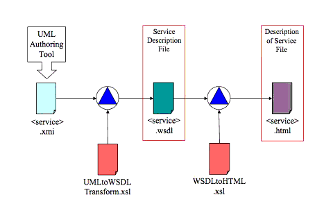
The transformation files are used to:
Details of these XSL files are given in I-BAT [GWS, 05f].
The transformation files use the information supplied in the UML description as described in Table 5.1. In Table 5.1 each attribute has an example value and for each set of values there follows the corresponding WSDL file. All of the attribute values are used in the single WSDL/XSD file.
The auto-generation files used to create the split file WSDL/XSD representation are shown in Figure 5.2.
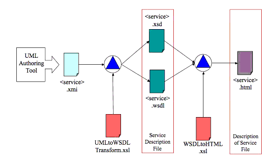
The transformation files are used to:
Details of these XSL files are given in I-BAT [GWS, 05f].
The transformation files use the information supplied in the UML description as described in Tables 5.2 and 5.3. In Tables 5.2 and 5.3 each attribute has an example value and for each set of values there follows the corresponding WSDL file. All of the attribute values are used in the split WSDL and XSD files.
The auto-generation files used to create the split file WSDL/XSD representation are shown in Figure 5.3.
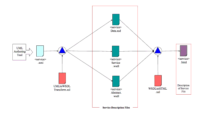
The transformation files are used to:
Details of these XSL files are given in I-BAT [GWS, 05f]. At the current time the files created for this approach have not been thoroughly tested in the .NET and J2EE tools and so their details are not presented.
The auto-generation files used to create the multiple files WSDL/XSD representation are shown in Figure 5.4.
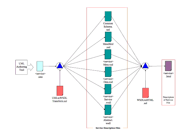
The transformation files are used to:
Details of these XSL files are given in I-BAT [GWS, 05f]. At the current time the files created for this approach have not been thoroughly tested in the .NET and J2EE tools and so their details are not presented.
At the current time IMS has not authorized the publication of the Asynchronous WSDL auto-generation as Final Release. This is because there are no validated implementations of this technique and there is work underway in W3C that could result in that IMS approach becoming proprietary. This work remains published as Public Draft material [GWS, 05a].
At the current time IMS has not authorized the publication of the Polled Communications WSDL auto-generation as Final Release. This is because there are no validated implementations of this technique and there is work underway in W3C that could result in that IMS approach becoming proprietary. This work remains published as Public Draft material [GWS, 05a].
The IMS bindings are controlled documents. It is recommended that changes take the form as recommended by the IMS Application Profile Guidelines [APG, 05a], [APG, 05b].
New capability should be added by creating new structures and not by changing a previously defined structure, i.e., instead of changing the definition of an operation a new operation should be created. The auto-generation files have been produced such that once they are re-applied to a new UML description then the new features are included within the new WSDL/XSD files. It is recommended that all new structure have a clear naming convention that show they are extensions to the original definition.
It is strongly recommended that a new service be produced by creating a new set of WSDL/XSD files and not by extending an established Service Group definition.
If it is undesirable or inappropriate to create a new Service Group set then a new service can be created by adding a new 'ServiceModel' package to the original UML definition (see the IMS Auto-generation Toolkit Manual [GWS, 05e] for more details on how this should be achieved). When the new service is defined it is recommended that:
It is strongly recommended that a new behavior is not produced by changing the definition of an established operation. Instead, a new operation should be created within its own 'interface' definition, i.e., the new operation should not be added to an established 'interface'. When new behaviors are defined it is recommended that:
The data structure definition can be extended by adding one or more new 'DataModel' packages. When a new 'DataModel' package is defined it is recommended that:
It is important to note that adding new 'DataModel' packages, as with adding any new Service or behavior, requires that the client are server parts of the system use the same WSDL/XSD definition. It is not possible to have just the client be constructed from the new service and leave the server with the original service definition. This will result in a service rejection and the corresponding SOAP failure code being generated and returned.
The only way to extend the service definition without requiring a change to both ends of the system is to use the data model extension classes. These classes allow the XSD to be extended without requiring a change to the XSD itself. However, this approach does not enable an XML parser to validate the modified data definition model.
It is possible to extend the SOAP header definitions using the auto-generation files. SOAP Header extensions should be inserted in the 'DataModel' package description for the Statusinfo class within the service WSDL files. The extensions should be given a new namespace to differentiate the extensions from the original definition.
In an IMS service-oriented specification the Conformance Specification is defined with respect to the Information Model and not to the binding. The binding must sustain the corresponding Information Model conformance statement. Conformance to the binding is expressed as part of the corresponding set of Application Profiles. An Application Profile is defined by the corresponding user community. Therefore, while it is not the responsibility of IMS to define the Conformance Specification for a service binding, IMS must supply the mechanisms by which a Conformance Specification for a binding can be created. This approach is based upon that used by WS-I.
WS-I has written the Conformance Claim Attachments Mechanism document [WSI, 04b]. This document catalogues mechanisms that can be used to attach WS-I Profile Conformance Claims to Web services artifacts, e.g., WSDL descriptions, UDDI registries, etc.
To allow advertisement of profile conformance, artifacts can be annotated with conformance claims, which use URIs to assert that a particular claim subject, e.g., an artifact or a party to a Web service, meets the appropriate requirements in the indicated profile. The requirements considered in-scope for a particular conformance claim are those placed upon the conformance target(s) associated with the claim attachment mechanism by the relevant profile. Therefore, every profile specifies its own conformance claim URI. Furthermore, every profile documents which of its conformance targets are in-scope for each claim attachment mechanism described in the following sections. In WS-I the appropriate claim attachments mechanisms are:
Apart from the WS-I Conformance Claims mechanism, the W3C is investigating the usage of WS-Policy. Therefore, no definitive recommendation is made on the usage of the WS-I approach. However, if some form of conformance statement is required then the WS-I approach can be used but no firm commitment is made to supporting this technique in later releases of the IMS GWS specification.
The tools that have been used to support the development of the auto-generation files are:
The open source Apache Axis web services engine is used to illustrate how one might implement a web service in Java beginning with a WSDL. Axis provides a utility class, org.apache.axis.wsdl.WSDL2Java, to use for generating client-side and server-side code from a WSDL. To generate stubs for making client-side service calls, execute WSDL2Java against your WSDL. By default WSDL2Java generates client-side code, which includes a class for each type specified in any schemas included in the types section of the WSDL, a stub that represents the call, a service locator implementation, and associated interfaces.
To generate server-side classes, execute WSDL2Java against a WSDL with the arguments "--server-side --skeletonDeploy true". The generated skeleton, the server-side equivalent of the client stub, sits between your implementation of the service and the Axis web service engine, and handles details such as mapping namespaces used in the WSDL onto generated Java classes. WSDL2Java also generates deployment descriptors for use in deploying the service to an Axis web services instance running in a J2EE servlet container such as Apache Tomcat. As in the client, classes are generated for schema types. WSDL2Java takes a number of arguments that allow you, among other things, to fetch a WSDL from a remote URL, map namespaces onto locally sensible package names, and generate Junit test cases. Axis also provides Ant methods that allow you to automate code generation and service deployment within an Ant build. At the end of the day, the Java developer is presented with a collection of familiar looking classes.
Axis can be obtained from the Apache site http://xml.apache.org/axis/.
The WSDL.EXE tool ships with Microsoft.NET and generates code for web services and web services clients using WSDL contract files, XSD schema files and "discomap" discovery documents. This paper focuses on code generation using WSDL. See 'MSDN Table2' (illustrating options for the WSDL.EXE tool) for examples and other code generation options using the WSDL.EXE tool.
The WSDL.EXE tool is automatically installed when Visual Studio or the .NET Framework 1.1 is installed. In Visual Studio 2003 the WSDL.EXE tool is located in the C:\Program Files\Microsoft Visual Studio .NET 2003\SDK\v1.1\Bin folder. A batch file is included to ensure the developer will have all of the .NET Tools included in the system PATH.
When you use WSDL.EXE to create a proxy class, a single source file is created in the programming language that you specify (see language option in the following tables). The WSDL.EXE tool determines the best type to use for objects specified in the service description. As a result, the generated type in the proxy class might not be what the developer wants or expects. To ensure correct object type casts, open the file containing the generated proxy class and change any incorrect object types to the expected object type. The WSDL.EXE tool expects all WSDL files to be specified on the command line. If your WSDL file imports additional schemas via one or more <wsdl:import> elements, a code generation error may occur. To get around this issue make sure you specify all of your schemas on the command line following the WSDL file. For example, if 'foo.wsdl' imports 'bar.xsd' which then imports 'example.xsd' the command line for the WSDL.EXE tool should be:
wsdl foo.wsdl bar.xsd example.xsd
The "location" attribute (in <wsdl:import>) and 'schemaLocation' attribute (in <xsd:import>) are "hints" that can be ignored by processors that provide alternate means to locate schemas (in accordance with the W3C WSDL and XSD Technical Recommendations).
The table on the following page summarizes the use of the WSDL.EXE tool.
| Argument | Description |
|---|---|
| URL |
The URL
to a WSDL file (.wsdl). |
| Path |
The path
to a local WSDL contract file (.wsdl), XSD schema file (.xsd), or
discovery document (.disco or .discomap). |
| Option | Description |
|---|---|
| /appsettingurlkey:key or /urlkey:key |
Specifies
the configuration key to use in order to read the default value
for the URL property when generating code. |
| /appsettingbaseurl:baseurl or /baseurl:baseurl |
Specifies
the base URL to use when calculating the URL fragment. The tool
calculates the URL fragment by converting the relative URL from
the baseurl argument to the URL in the WSDL document. You must
specify the /appsettingurlkey option with this option. |
| /d[omain]:domain |
Specifies
the domain name to use when connecting to a server that requires
authentication. |
| /l[anguage]:language |
Specifies
the language to use for the generated proxy class. You can
specify CS (C#; default), VB (Visual Basic), JS (JScript) or VJS
(Visual J#) as the language argument. You can also specify the
fully qualified name of a class that implements the
System.CodeDom.Compiler.CodeDomProvider Class. http://msdn.microsoft.com/library/en-us/cpref/html/frlrfSystemCodeDomCompilerCodeDomProviderClassTopic.asp |
| /n[amespace]:namespace |
Specifies
the namespace for the generated proxy or template. The default
namespace is the global namespace. |
| /nologo |
Suppresses the Microsoft startup banner
display. |
| /o[ut]:filename |
Specifies
the file in which to save the generated proxy code. The tool
derives the default file name from the XML Web service name. The
tool saves generated datasets in different files. |
| /parsableerrors |
Displays
errors in a format similar to the error reporting format used by
language compilers. |
| /p[assword]:password |
Specifies
the password to use when connecting to a server that requires
authentication. |
| /protocol:protocol |
Specifies
the protocol to implement. You can specify SOAP (default),
HttpGet, HttpPost, or a custom protocol specified in the
configuration file. |
| /proxy:URL |
Specifies
the URL of the proxy server to use for HTTP requests. The default
is to use the system proxy setting. |
| /proxydomain:domain or /pd:domain |
Specifies
the domain to use when connecting to a proxy server that requires
authentication. |
| /proxypassword:password or /pp:password |
Specifies
the password to use when connecting to a proxy server that
requires authentication. |
| /proxyusername:username or /pu:username |
Specifies
the user name to use when connecting to a proxy server that
requires authentication. |
| /server |
Generates
an abstract class for an XML Web service based on the contracts.
The default is to generate client proxy classes. |
| /u[sername]:username |
Specifies
the user name to use when connecting to a server that requires
authentication. |
| /? |
Displays
command syntax and options for the tool. |
Configuration and Deployment Tools:
The further work to be undertaken on the development of the auto-generation files is:
All of the following data structures are either defined within the WSDL files or supplied in the external XSD file: "imsMessBindSchemav1p0.xsd"3.
The 'StatusInfo' class diagram is shown in Figure A1.1. This class is used to return the status information reporting on the outcome of the associated request.
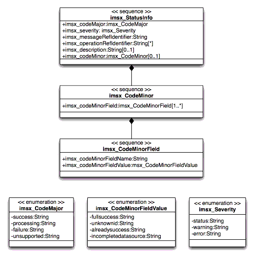
The set of attributes for the 'StatusInfo' class are summarized in Table A1.1.
The associated object constraint language description for this class is:
inv: Set{success, processing, failure, unsupported}.includes(codeMajor)
inv: Set{status, warning, error}.includes(severity)
inv: codeMinorValue.size <= 32
inv: messageRefIdentifier.size <= 32
inv: operationRefIdentifier.size <= 32
CodeMajor/Severity Interpretation Matrix
The interpretation of the 'CodeMajor/Severity' matrix is shown in Table A1.2.
The set of predefined 'CodeMinor' codes is shown in Table A1.3 (these is an initial set of common codes - each specification is expected to define its own set of codes).
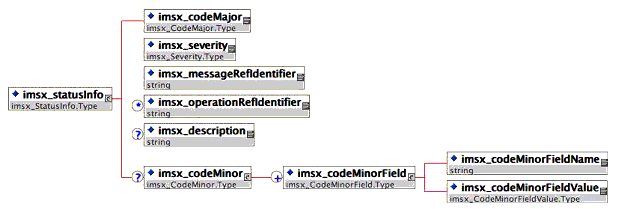
The XML binding for the Identifier class is shown in Figure A1.2. This binding is based upon the creation of the complex-type StatusInfo.Type.
The StatusInfoSet class diagram is shown in Figure A1.3. This is a collection of StatusInfo classes and the order of these reflects the sequence in which the individual operations were requested.
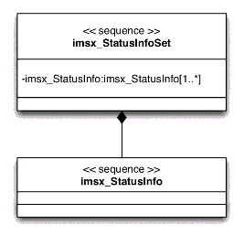
The set of associations for the StatusInfoSet class are summarized in Table A1.4.
| Association Class Name | Multiplicity | Description |
|---|---|---|
| StatusInfo |
1..* |
The
status information class returned for each and every operation.
Each StatusInfo instance references the status of each
operation. |
The XML binding for the Identifier class is shown in Figure A1.4. This binding is based upon the creation of the complex-type 'StatusInfoSet.Type'.
The following structures are the message headers that are to be used in the synchronous, asynchronous and polled message choreographies to implement the behaviors (these choreographies are described in [GWS, 05b]).
The synchronous request message header structure is shown in Figure A2.1. This header is attached to the request message issued by the client system. The 'wildCard' extension element enables any new namespaced element(s) to used.

This is the container for the version of the GWS infrastructure being employed. It is an enumerated field. This is an optional field and if not used then the default value should be assumed to be '1.0'.
This is the container for the unique message identifier. This is to be assigned by the system constructing the message header. It is the responsibility of the transmitting system to ensure that the message identifier is unique.
The synchronous response message header structure is shown in Figure A2.2. This header is attached to the response message issued by the server system. The 'wildCard' extension element enables any new namespaced element(s) to used.
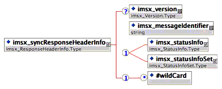
This is the container for the version of the GWS infrastructure being employed. It is an enumerated field. This is an optional field and if not used then the default value should be assumed to be '1.0'.
This is the container for the unique message identifier. This is to be assigned by the system constructing the message header. It is the responsibility of the transmitting system to ensure that the message identifier is unique.
The status information returned as a response to single transaction request; see sub-section A1.1.
The status information returned as a response to multiple transaction request; see sub-section A1.2.
At the current time IMS has not authorized the publication of the Asynchronous WSDL messaging in the Final Release. This is because there are no validated implementations of this technique and there is work underway in W3C that could result in the IMS approach becoming proprietary. This work remains published as Public Draft material [GWS, 05a].
At the current time IMS has not authorized the publication of the Polled WSDL messaging in the Final Release. This is because there are no validated implementations of this technique and there is work underway in W3C that could result in the IMS approach becoming proprietary. This work remains published as Public Draft material [GWS, 05a].
| Title |
IMS
General Web Services WSDL Binding Guidelines |
| Editor |
Colin
Smythe (IMS) |
| Team Co-Leads |
Cathy
Schroeder (Microsoft Corp.), James Simon (SUN Microsystems
Corp.) |
| Version |
1.0 |
| Version Date |
19
December 2005 |
| Status |
Final Specification |
| Summary |
This
document explains how to create a WSDL binding for specifications
based upon the IMS General Web Services Base Profile and the
Extension Profiles. This auto-generation is achieved using a set
of transformation tools that are applied to the Unified Modelling
Language-based description of the information model of the
specification to create the equivalent WSDL. The auto-generation
tools support bindings for the different communications models
supported as part of the IMS General Web Services Base
Profile. |
| Revision
Information |
19
December 2005 |
| Purpose |
This
document is circulated for public adoption. This document is to
be adopted by IMS and all other organizations that wish to
construct service-based interoperability specifications using Web
Services. |
| Document Location |
http://www.imsglobal.org/gws/gwsv1p0/imsgws_wsdlBindv1p0.html |
| To
register any comments or questions about this specification
please visit:
http://www.imsglobal.org/developers/ims/imsforum/categories.cfm?catid=20 |
The following individuals contributed to the development of this document:
A
a-API 1
Abstract Framework 1, 2, 3, 4
API 1, 2, 3
Application Profile 1, 2, 3
Asynchronous 1, 2, 3, 4, 5
B
Base Profile 1, 2, 3, 4, 5, 6, 7
Best Practice 1
C
Conformance 1, 2, 3, 4
Context 1, 2
CRUD 1
D
DCOM 1
G
General Web Services Base
Profile 1
I
IMS Auto-generation Binding
Tool 1, 2, 3, 4, 5, 6, 7
IMS General Web Services
1, 2, 3, 4, 5, 6, 7, 8, 9, 10, 11, 12, 13, 14
Addressing Profile
1
Attachments Profile
1
Base Profile 1, 2, 3, 4, 5, 6, 7
Security Profile 1
M
Messaging
Asynchronous 1, 2, 3, 4, 5
Polled 1, 2, 3, 4, 5
Synchronous 1, 2, 3, 4, 5, 6, 7
MOM 1
P
Protocols
FTP 1
HTTP 1, 2, 3
HTTPS 1
IIOP 1
IP 1
SMTP 1
SOAP 1, 2, 3, 4, 5, 6, 7, 8, 9, 10, 11, 12, 13, 14, 15, 16
SSL 1, 2
TCP 1, 2
TLS 1, 2
Q
Quality of Service 1
S
Security 1, 2, 3
SOAP 1, 2, 3, 4, 5, 6, 7, 8, 9, 10, 11, 12, 13, 14, 15, 16
SOAP Versions
1.1 1
1.2 1
Synchronous 1, 2, 3, 4, 5, 6, 7
T
TCP 1, 2
TLS 1, 2
Transport Layer Security
1, 2
U
UDDI 1, 2
Unified Modelling Language
1, 2, 3, 4, 5, 6, 7, 8, 9, 10, 11, 12, 13, 14
UML 1, 2, 3, 4, 5, 6, 7, 8, 9, 10, 11, 12, 13
W
W3C 1, 2, 3, 4, 5, 6, 7, 8, 9, 10, 11, 12, 13
Web Services 1, 2, 3, 4, 5, 6, 7, 8, 9, 10
SOAP 1, 2, 3, 4, 5, 6, 7, 8, 9, 10, 11, 12, 13, 14, 15, 16
WSDL 1, 2, 3, 4, 5, 6, 7, 8, 9, 10, 11, 12, 13, 14, 15, 16, 17, 18, 19, 20, 21, 22, 23, 24, 25, 26, 27, 28, 29, 30, 31, 32, 33, 34, 35, 36, 37, 38, 39, 40, 41, 42, 43, 44, 45
Web Services Interoperability
Organization 1,
2, 3, 4, 5, 6, 7, 8, 9
WSDL 1, 2, 3, 4, 5, 6, 7, 8, 9, 10, 11, 12, 13, 14, 15, 16, 17, 18, 19, 20, 21, 22, 23, 24, 25, 26, 27, 28, 29, 30, 31, 32, 33, 34, 35, 36, 37, 38, 39, 40, 41, 42, 43, 44, 45
WSDL Versions
1.1 1
2.0 1
WS-I
Basic Profile 1, 2, 3
Simple SOAP Binding
Profile 1
WS-I Basic Profile 1, 2, 3
WS-I Simple SOAP Binding
Profile 1
X
XMI 1, 2, 3, 4, 5, 6, 7
XML 1, 2, 3, 4, 5, 6, 7, 8, 9, 10, 11, 12, 13, 14, 15, 16
XML Metadata Interface
1
XML Schema 1, 2
XML Schema Definition 1
XSD 1, 2, 3, 4, 5, 6, 7, 8, 9, 10, 11, 12, 13, 14, 15, 16, 17, 18, 19, 20, 21, 22, 23, 24, 25, 26, 27, 28, 29, 30, 31, 32, 33
XSLT 1, 2, 3
IMS Global Learning Consortium, Inc.
("IMS/GLC") is publishing the information contained in this
IMS General Web Services WSDL Binding Guidelines
("Specification") for purposes of scientific, experimental,
and scholarly collaboration only.
IMS/GLC makes no warranty or representation regarding the
accuracy or completeness of the Specification.
This material is provided on an "As Is" and "As Available"
basis.
The Specification is at all times subject to change and revision
without notice.
It is your sole responsibility to evaluate the usefulness,
accuracy, and completeness of the Specification as it relates to
you.
IMS/GLC would appreciate receiving your comments and
suggestions.
Please contact IMS/GLC through our website at http://www.imsglobal.org
Please refer to Document Name: IMS General Web Services WSDL
Binding Guidelines Revision: 19 December 2005