UML: Creating Activity Diagrams
Contributed and maintained by Cindy Castillo, Bob May
November 2007 [Revision number: V1-4]
This publication is applicable to NetBeans IDE 6.0 release
In this tutorial, you learn how to use the UML features of the IDE to create a simple UML activity diagram. The steps in this tutorial show one representative way of creating an activity diagram and introduce you to some of the features offered by NetBeans UML. This tutorial does not teach you about UML concepts or the Java programming language.
Expected duration: 30 minutes
Contents
Tutorial Requirements
Before you proceed, make sure you review the requirements in this section.
This tutorial assumes that your system meets the requirements specified in the Systems Requirements section of the NetBeans 6.0 Release Notes.
Prerequisites
To use this tutorial, the IDE must be installed on your system and you should be familiar with the basic parts of the IDE. You should also have a basic familiarity with the Java programming language and UML. For a basic understanding of the IDE, see the IDE Basics topics in the online help. A good resource for UML techniques and theory is the official UML resource page at http://www.uml.org/.
Software Needed for the Tutorial
Before you begin, download and install the following software:
- NetBeans 6.0
Select the All Download option.
top
Activity Diagram - an Overview
An Activity diagram is a visual representation of any system's activities and flows of data or decisions between activities. When you click the Diagram editor tab for an Activity diagram, the IDE displays a specific selection of icons in the IDE Modeling Palette. Activity diagrams provide a very broad view of a business process.
The diagram may be used to:
- Describe activities and flows of data or decisions between activities
- Provide a broad view of business processes
- Describe the activities that occur within a use case
- Show many different activities using different discrete symbols
- Show parallel threads
The following shows the tasks involved in creating an Activity diagram. This table and the following procedures describe one way to create an Activity diagram.
- Set Up the Activity Diagram
- Create a UML Project
- Create a Package with Empty Scoped Activity Diagram
- Place Partitions
- Add Partitions
- Add Subpartitions
- Identify Action States
- Add Elements
- Add Activity Group
- Add Invocation
- Add Initial Node Element
- Add Horizontal Fork Element
- Add Activity Final Node and Decision Node
- Place Edges and Dependencies
- Add Activity Edge
- Add Dependencies
- Label the Edges
- Work with Group Kinds and Conditions
- Add Guard Conditions to Activity Edges
- Select and Modify GroupKinds
top
Setting Up the Activity Diagram
To create an Activity diagram, you must first create the UML project and a Java package to contain an empty scoped activity diagram. This section contains the following procedures:
Creating a UML Project
- From the main menu, choose File > New Project and then do the following:
- Under Categories, select UML.
- Under Projects, select Platform-Independent Model.
- Click Next.
- Type
ActivityDiagProj for the project name and ActivityDiagTut for the location for your project.
Notice that when you type the Project Name, the IDE automatically suggests this name for the name of the Project Folder.
- Click Finish.
The New Wizard opens and displays the Create New Diagram page.
- For the purposes of this example, click Cancel.
The IDE does the following:
- Creates an empty Platform Independent modeling project
- Displays the project icon in the Projects window
top
Creating a Package With Scoped Activity Diagram
- In the Projects window, right-click the Model node.
- Choose Add > Package from the pop-up menu.
- In the Name field type
ActDiagPkg as the name for your package.
- Accept the default value in the Namespace field.
- Select the Create Scoped Diagram checkbox.
- In the Diagram Name field, type
actDiagram as the name for your diagram.
- From the Diagram Type list, select Activity Diagram and click Finish.
The IDE does the following:
- Creates a package node under the Model node with the package name that you entered
- Creates a diagram node under the package node
- Displays the new diagram in the Diagram editor (the diagram is empty at this point)
- Opens the Modeling Palette displaying the icons that are used to build activity diagrams
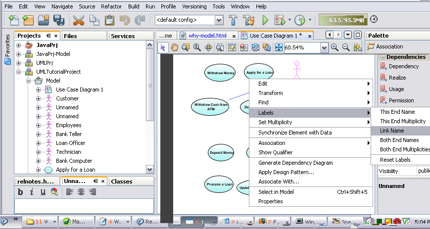
The IDE should resemble the following figure:
top
Placing Partitions
The IDE lets you add partitions to your activity diagram. Partitions divide the nodes and edges to constrain and show a view of the contained nodes.
- From the Data section of the Modeling Palette, select the Partition icon
 .
.
- Click in the Diagram editor to place a Partition element on the diagram.
An unnamed Partition element is placed on the Diagram editor.
- Deselect the Partition icon by right-clicking anywhere in the Diagram editor.
- Elongate the rectangle in the left side of the Diagram editor.
- With the Partition element selected, right-click and choose Partitions > Add Partition Column to the Right from the pop-up menu.
- Expand the right column of the partition.
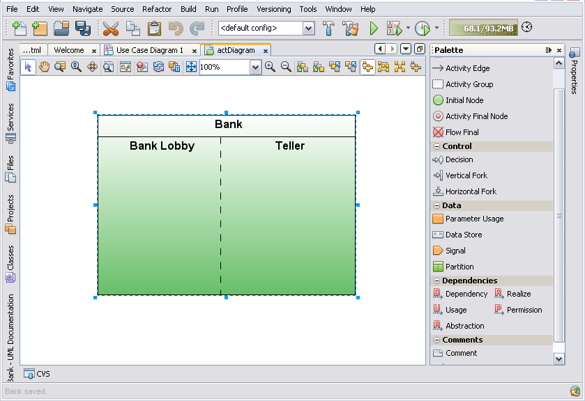
- Name the partition by double-clicking the word Unnamed in the top portion of the partition and typing Bank.
- Press Enter.
- Name the left column by double-clicking the word Unnamed in the left column and typing Bank Lobby.
- Name the right column Teller.
Your diagram should resemble the following figure.
top
Identifying Action States
This section contains the following procedures:
Adding an Activity Group
- From the Basic section of the Modeling Palette, select the Activity Group icon
 .
.
- Click inside the Bank Lobby subpartition in the Diagram editor to place the Activity Group element on the diagram inside the left subpartition.
This nests the Activity Group inside the Bank Lobby subpartition.
- Right-click to deselect the icon.
- Double-click the word Unnamed on the new Activity Group, type Customer and press Enter.
- Select the Activity Group that you just added. Move and enlarge it to almost fill this subpartition.
top
Adding an Invocation
- From the Basic section of the Modeling Palette, select the Invocation icon
 .
.
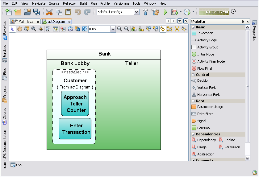
- Click inside the Customer Activity Group element in the Bank Lobby subpartition to place two invocation elements on the diagram, one directly below the other.
- Deselect the icon.
- Move and resize the invocation elements so that they fit completely inside the Customer Activity Group as shown in the following figure.
- Double-click the upper invocation node that you just added, type Approach Teller Counter and press Enter to label the element.
- Select the lower invocation node and name it Enter Transaction.
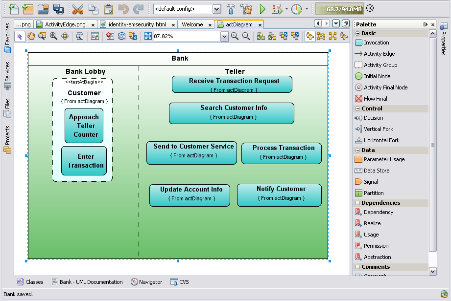
- Place six more invocation elements inside the Teller subpartition and name them as follows:
- Receive Transaction Request
- Search Customer Info
- Send to Customer Service
- Process Transaction
- Update Account Info
- Notify Customer
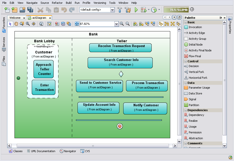
Your diagram should resemble the following figure.
top
Adding an Initial Node Element
- From the Basic section of the Modeling Palette, select the Initial Node icon
 .
.
- Click in the Bank Lobby subpartition to the left of the Approach Teller Counter element.
- Deselect the icon.
top
Adding a Horizontal Fork Element
- From the Control section of the Modeling Palette, click the Horizontal Fork icon
 .
.
- Place the bar representing the Horizontal Fork element above the Update Account Info and Notify Customer invocation elements
- Deselect the icon.
- Lengthen the bar to span the width of both invocations.
- Place another Horizontal Fork element below the Update Account Info and Notify Customer invocation elements and lengthen the bar to span the width of both invocations.
top
Adding an Activity Final Node and a Decision Node
- From the Basic section of the Modeling Palette, select the Activity Final Node icon
 .
.
- Place the Final Node below the lower Horizontal Fork element.
- Deselect the Activity Final Node icon.
- From the Control section of the Modeling Palette, select the Decision icon
 .
.
- Place the Decision element on the flow between Search Customer Info and Send To Customer Service elements.
Your diagram should resemble the following figure.
- Deselect the Decision icon.
top
Placing Edges and Dependencies
This section contains the following procedures:
Adding an Activity Edge Element
- From the Basic section of the Modeling Palette, select the Activity Edge icon
 .
.
You use the Activity Edge to connect the Initial Node element to the Invocation element.
- Click once on the Initial Node element and click again on the invocation element that is labeled Approach Teller Counter.
An Activity Edge link now connects the two elements. The labels for the Activity Edge links are hidden and need to be displayed.
- Deselect the icon by right-clicking anywhere in the Diagram editor.
- Select and right-click the Activity Edge element.
- Choose Labels > Show Name from the pop-up menu.
The link is labeled with the highlighted text Unnamed.
- To name the link, type Initiate Cash Withdrawal and press Enter.
top
Adding More Activity Edge Elements
- Select the Activity Edge icon from the Basic section of the Modeling Palette.
- Draw the following links:
- From Approach Teller Counter to Enter Transaction
- From Enter Transaction to Receive Transaction Request
- From Receive Transaction Request to Search Customer Info
- From Search Customer Info to Decision node
- From Decision node to Send To Customer Service
- From Decision node to Process Transaction
- From Process Transaction to Upper Horizontal Fork
- From Upper Horizontal Fork to Update Account Info and Notify Customer
- From Notify Customer to Lower Horizontal Fork
- From Update Account Info to Lower Horizontal Fork
- From Lower Horizontal Fork to Final State element
- Right-click to deselect the icon.
Your diagram should now resemble the following figure:

top
Working with Group Kinds and Conditions
This section contains the following procedures:
Adding Guard Conditions to Activity Edges
The UML feature lets you add Guard Conditions to an Activity diagram in the Properties window or in the Diagram editor.
- In the Diagram editor, right-click the Activity Edge element between the Decision node and the Send to Customer Service element.
- Choose Labels < Show Guard Condition from the pop-up menu.
- Inside the guard condition brackets, type No Customer Info and press Enter.
- Repeat steps 2 and 3 for the Activity Edge between Decision node and Process Transaction. Type Customer Info for this guard condition.
top
Selecting and Modifying the GroupKind Property
In the IDE, an Activity Group depicts a loop in the flow of an activity. For example, an Activity Group calls out an iteration that already exists in the flow. The IDE's UML feature offers three Group Kinds as follows:
- Iteration
- Structured
- Interruptible
- In the Diagram editor, select the Activity Group labeled Customer.
- In the Properties window on the GroupKind property row, click the down arrow.
- Select Structured from the drop-down list.
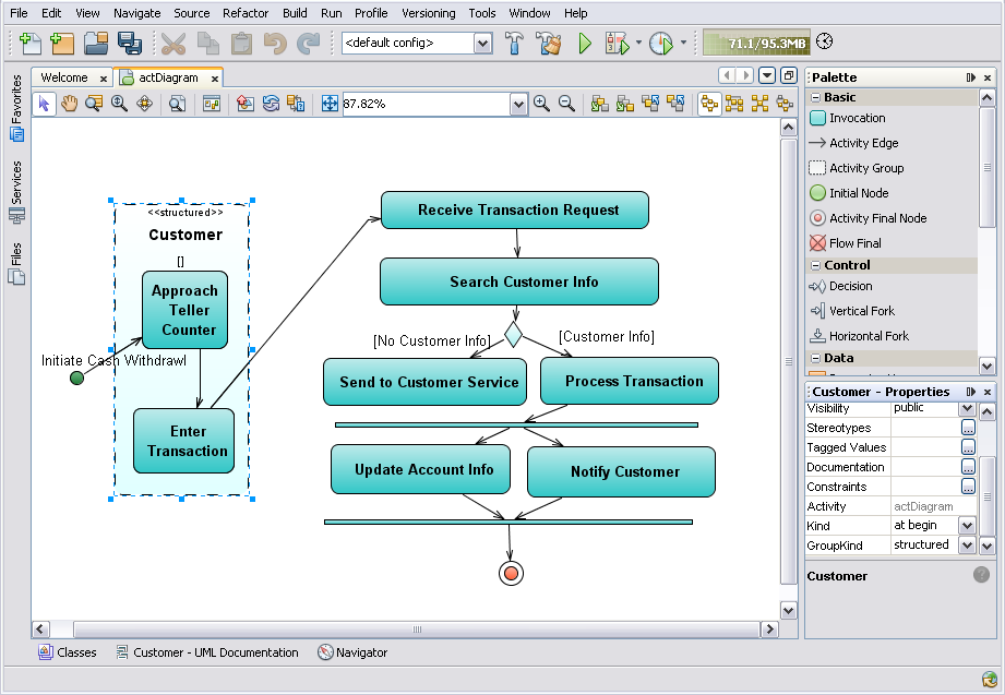
The Customer Activity Group is relabeled on the diagram as a structured group.
The finished Activity diagram should resemble the following figure:
top
Summary
In this article, you created an activity diagram for a simple banking application. You learned how to create a representative Activity diagram using the features offered by NetBeans UML.
top
Next Steps
To send comments and suggestions, obtain support, and stay informed of the latest
changes to the NetBeans IDE J2EE development features, join the [email protected]
mailing list.
top
>> More NetBeans IDE Documentation


