| Prev | Part VI. Programming With Components Chapter 26. User guide |
 |
Next |
This chapter explains the specific features and functionalities of the GCM Implementation.
The Architecture Description Languages (ADL) are a way to describe software and/or system architectures. ADLs facilitate application description without concern for the underlying implementation code and foster code reuse as an effect of decoupling the implementation from the architecture. Architectures created by using ADLs are composed of predefined entities with various connectors that communicate through defined connections. To define an architecture through an ADL we can use a textual syntax and/or a graphical syntax, possibly associated with a design tool.
In the case of ProActive we have developed the Grid Component Model which is an extension of the Fractal ADL. For detailed information on Fractal read Fractal ADL tutorial . In our GCM implementation this mechanism is used to configure and deploy component systems through normalized XML files. Thanks to a specific XML DTD, it specifies a definition for each component of the application. For instance, it usually describes component interfaces, component bindings, component attributes, the subcomponents in the case of a composite component, the virtual node where the component will be deployed, and so on. As it is an extension of the standard Fractal ADL, GCM allows reusing and integrating ProActive-specific features such as distributed deployment using deployment descriptors, active objects, virtual nodes, etc. For example, in the case of virtual nodes the components ADL has to be associated with a deployment descriptor (this is done at parsing time: both files are given to the parser).
Note that because GCM is based on the Fractal ADL, it
requires the following libraries which are included in the
/lib
directory of the ProActive distribution :
fractal-adl.jar
,
dtdparser.jar
,
ow_deployment_scheduling.jar
.
Components are defined in definition files, which are .fractal files. Here is a simple example of an ADL file extract from the example Helloworld retrievable at Examples/org.objectweb.proactive.examples.components.helloworld.
  <?xml version="1.0" encoding="ISO-8859-1" ?>
  <!DOCTYPE definition PUBLIC "-//objectweb.org//DTD Fractal ADL 2.0//EN"
 "classpath://org/objectweb/proactive/core/component/adl/xml/proactive.dtd">

  <definition name="org.objectweb.proactive.examples.components.helloworld.HelloWorld">
    <interface name="m" role="server" signature=
"org.objectweb.proactive.examples.components.helloworld.Main"/>

    <component name="client" definition=
"org.objectweb.proactive.examples.components.helloworld.ClientImpl"/>
    <component name="server">
      <interface name="s" role="server" signature=
"org.objectweb.proactive.examples.components.helloworld.Service"/>
     <content class="ServerImpl"/>
     <attributes signature=
"org.objectweb.proactive.examples.components.helloworld.ServiceAttributes">
       <attribute name="header" value="-> "/>
       <attribute name="count" value="1"/>
     </attributes>
     <controller desc="primitive"/>
   </component>

   <binding client="this.m" server="client.m"/>
   <binding client="client.s" server="server.s"/>

   <controller desc="composite"/>

   <virtual-node name="helooworld-node" cardinality="single"/>
 </definition>
Now, here is a detailed description of each lines:
1: Classical prologue of XML files.
2-3: The syntax of the document is validated against a DTD retrieved from the classpath.
5: The definition element has a name (which must be the same name that the file's) and inheritance is supported through the attribute 'extends'.
6: The interface element allows to specify interfaces of the current enclosing component.
9-21: Nesting is allowed for composite components and is done by adding other component elements. Components can be specified and created in this definition, and these components can themselves be defined here or in other definition files.
14: Primitive components specify the content element, which indicates the implementation class containing the business logic for this component.
15-19: Components can specify a attributes element, which allows to initialize attributes of a component.
23-24: The binding element specifies bindings between interfaces of components and specifying 'this' as the name of the component refers to the current enclosing component.
26: The controller elements can have the following 'desc' values: 'composite' or 'primitive'.
28: The virtual-node element offers distributed deployment information. It can be exported and composed in the exportedVirtualNodes element.
The component will be instantiated on the virtual node it specified (or the one that it exported). For a composite component, it means it will be instantiated on the (first if there are several nodes mapped) node of the virtual node. For a primitive component, if the virtual node defines several nodes (cardinality='multiple'), there will be as many instances of the primitive component as there are underlying nodes. Each of these instances will have a suffixed name looking like:
primiveComponentName-cyclicInstanceNumber-n
where primitiveComponentName is the name defined in the ADL.
The syntax is similar to the standard Fractal ADL, and the parsing engine has been extended. Features specific to ProActive are:
Virtual nodes have a cardinality property: either 'single' or 'multiple'. When 'single', it means the virtual node in the deployment descriptor should contain 1 node ; when 'multiple', it means the virtual node in the deployment descriptor should contain more than 1 node.
Virtual nodes can be exported and composed .
Template components are not handled.
The validating DTD has to be specified as: classpath://org/objectweb/proactive/core/component/adl/xml/proactive.dtd
Components are deployed on the virtual node that is specified in their definition ; it has to appear in the deployment descriptor unless this virtual node is exported. In this case, the name of the exported virtual node should appear in the deployment descriptor, unless this exported virtual node is itself exported.
When exported, a virtual node can take part in the composition of other exported virtual nodes. The idea is to further extend reusability of existing (and packaged, packaging being a forthcoming feature of Fractal) components.
In the example, the component defined in helloworld-distributed-wrappers.fractal exports the virtual nodes VN1 and VN2:
				exportedVirtualNodes exportedVirtualNode name='VN1'
				composedFrom composingVirtualNode component='client'
				name='client-node' /composedFrom /exportedVirtualNode
				exportedVirtualNode name='VN2' composedFrom
				composingVirtualNode component='server'
				name='server-node'/ /composedFrom /exportedVirtualNode
				/exportedVirtualNodes
VN1 is composed of the exported virtual node 'client-node' from the component named client
In the definition of the client component (ClientImpl.fractal), we can see that client-node is an exportation of a virtual node which is also name 'client-node':
				exportedVirtualNodes exportedVirtualNode
				name='client-node' composedFrom composingVirtualNode
				component='this' name='client-node'/ /composedFrom
				/exportedVirtualNode /exportedVirtualNodes ...
				virtual-node name='client-node' cardinality='single'/
Although this is a simplistic example, one should foresee a situation where ClientImpl would be a prepackaged component, where its ADL could not be modified ; the exportation and composition of virtual nodes allow to adapt the deployment of the system depending on the existing infrastructure. Colocation can be specified in the enclosing component definition (helloworld-distributed-wrappers.fractal):
				exportedVirtualNodes exportedVirtualNode name='VN1'
				composedFrom composingVirtualNode component='client'
				name='client-node' composingVirtualNode
				component='server' name='server-node'/ /composedFrom
				/exportedVirtualNode /exportedVirtualNodes
As a result, the client and server component will be colocated / deployed on the same virtual node. This can be profitable if there is a lot of communications between these two components.
When specifying 'null' as the name of an exported virtual node, the components will be deployed on the current virtual machine. This can be useful for debugging purposes.
ADL definitions correspond to component factories. ADL definition can be used directly:
					Factory factory = org.objectweb.proactive.core.component.adl.FactoryFactory.getFactory();
					Map context = new HashMap();
					Component c = (Component) factory.newComponent("myADLDefinition",context);
It is also possible to use the launcher tool, which
parses the ADL, creates a corresponding component
factory, and instantiates and assembles the components
as defined in the ADL, is started from the
org.objectweb.proactive.core.component.adl.Launcher
class:
				Launcher [-java|-fractal] <definition>
				[<itf>] [deployment-descriptor])
where [-java|-fractal] comes from the Fractal ADL Launcher (put -fractal for ProActive components, this will be made optional for ProActive components in the next release), <definition> is the name of the component to be instantiated and started, <itf> is the name of its Runnable interface, if it has one, and <deployment-descriptor> the location of the ProActive deployment descriptor to use. It is also possible to use this class directly from its static main method.
In this chapter, we consider multiway communications - communications to or from several interfaces - and notably parallel communications, which are common in Grid computing.
Our objective is to simplify the design of distributed Grid applications with multiway interactions.
The driving idea is to manage the semantics and behavior of collective communications at the level of the interfaces.
Grid computing uses the resources of many separate computers connected by a network (usually the Internet) to solve large-scale computation problems. Because of the number of available computers, it is fundamental to provide tools for facilitating communications to and from these computers. Moreover, Grids may contain clusters of computers, where local parallel computations can be very efficiently performed - this is part of the solution for solving large-scale computation problems - , which means that programming models for Grid computing should include parallel programming facilities. We address this issue, in the context of a component model for Grid computing, by introducing collective interfaces .
The component model that we use, Fractal, proposes two kinds of cardinalities for interfaces, singleton or collection , which result in one-to-one bindings between client and server interfaces. It is possible though to introduce binding components, which act as brokers and may handle different communication paradigms. Using these intermediate binding components, it is therefore possible to achieve one-to-n, n-to-one or n-to-n communications between components. It is not possible however for an interface to express a collective behavior: explicit binding components are needed in this case.
We propose the addition of new cardinalities in the specification of Fractal interfaces, namely multicast and gathercast . Multicast and gathercast interfaces give the possibility to manage a group of interfaces as a single entity (which is not the case with a collection interface, where the user can only manipulate individual members of the collection), and they expose the collective nature of a given interface. Moreover, specific semantics for multiway invocations can be configured, providing users with flexible communications to or from gathercast and multicast interfaces. Lastly, avoiding the use of explicit intermediate binding components simplifies the programming model and type compatibility is automatically verified.
The role and use of multicast and gathercast interfaces are complementary. Multicast interfaces are used for parallel invocations, whereas gathercast interfaces are used for synchronization and gathering purposes.
Note that in our implementation of collective interfaces, new features of the Java language introduced in Java 5 are extensively used, notably annotations and generics.
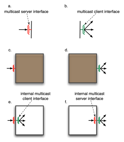
A multicast interface transforms a single invocation into a list of invocations
A multicast interface is an abstraction for 1-to-n communications. When a single invocation is transformed into a set of invocations, these invocations are forwarded to a set of connected server interfaces. A multicast interface is unique and it exists at runtime (it is not lazily created). The semantics of the propagation of the invocation and of the distribution of the invocation parameters are customizable (through annotations), and the result of an invocation on a multicast interface - if there is a result - is always a list of results.
Invocations forwarded to the connected server interfaces occur in parallel, which is one of the main reasons for defining this kind of interface: it enables parallel invocations, with automatic distribution of invocation parameters .
A multicast invocation leads to the invocation services offered by one or several connected server interfaces, with possibly distinct parameters for each server interface.
If some of the parameters of a given method of a multicast interface are lists of values, these values can be distributed in various ways through method invocations to the server interfaces connected to the multicast interface. The default behavior - namely broadcast - is to send the same parameters to each of the connected server interfaces. In the case some parameters are lists of values, copies of the lists are sent to each receiver. However, similar to what SPMD programming offers, it may be adequate to strip some of the parameters so that the bound components will work on different data. In MPI for instance, this can be explicitly specified by stripping a data buffer and using the scatter primitive.
The following figure illustrates such distribution mechanisms: broadcast (a.) and scatter (b.)
Invocations occur in parallel and the distribution of parameters is automatic.
4 modes of distribution of parameters are provided by default, and define distribution policies for lists of parameters:
BROADCAST, which copies a list of parameters and sends a copy to each connected server interface.
ParamDispatchMode.BROADCAST
ONE-TO-ONE, which sends the ith parameter to the connected server interface of index i. This implies that the number of elements in the annotated list is equal to the number of connected server interfaces.
ParamDispatchMode.ONE_TO_ONE
ROUND-ROBIN, which distributes each element of the list parameter in a round-robin fashion to the connected server interfaces.
ParamDispatchMode.ROUND_ROBIN
RANDOM, which distributes each element of the list parameter in a random manner to the connected server interfaces.
ParamDispatchMode.RANDOM
UNICAST, which sends only one of the
list parameter to one of the connected
server interfaces. Which argument and
which server interface is determined by
a custom controller that extends
org.objectweb.proactive.core.component.controller.MulticastController
.
ParamDispatchMode.UNICAST
It is also possible to define a custom
distribution by specifying the distribution
algorithm in a class which implements the
org.objectweb.proactive.core.component.type.annotations.multicast.ParamDispatch
interface.
							@ParamDispatchMetadata(mode
							=ParamDispatchMode.CUSTOM, customMode =
							CustomParametersDispatch.class))
Note that our implementation of collective interfaces extensively uses new features of the Java language introduced in Java 5, such as generics and annotations.
The distribution of parameters in our framework is specified in the definition of the multicast interface, using annotations.
Elements of a multicast interface which can be annotated are: interface, methods and parameters. The different distribution modes are explained in the next section. The examples in this section all specify broadcast as the distribution mode.
A distribution mode declared at the level of the interface defines the distribution mode for all parameters of all methods of this interface, but may be overridden by a distribution mode declared at the level of a method or of a parameter.
The annotation for declaring distribution
policies at level of an interface is
@org.objectweb.proactive.core.component.type.annotations.multicast.ClassDispatchMetadata
and is used as follows:
								@ClassDispatchMetadata(mode=@ParamDispatchMetadata(mode=ParamDispatchMode.BROADCAST))
								interface MyMulticastItf {

									public void foo(List<T> parameters);
								}
A distribution mode declared at the level of a method defines the distribution mode for all parameters of this method, but may be overridden at the level of each individual parameter.
The annotation for declaring distribution
policies at level of a method is
@org.objectweb.proactive.core.component.type.annotations.multicast.MethodDispatchMetadata
and is used as follows:
								@MethodDispatchMetadata(mode=@ParamDispatchMetadata(mode=ParamDispatchMode.BROADCAST))
								public void foo(List<T> parameters);
The annotation for declaring distribution
policies at level of a parameter is
@org.objectweb.proactive.core.component.type.annotations.multicast.ParamDispatchMetadata
and is used as follows:
								public void foo(@ParamDispatchMetadata(mode=ParamDispatchMode.BROADCAST)
														List<T> parameters);
For each method invoked and returning a result
of type
T
, a multicast invocation returns an aggregation
of the results: a
List<T>
.
There is a type conversion, from return type
T
in a method of the server interface, to return
type
List<T>
in the corresponding method of the multicast
interface. The framework transparently handles
the type conversion between return types, which
is just an aggregation of elements of type
T
into a structure of type
list<T>
.
This implies that, for the multicast interface,
the signature of the invoked method has to
explicitly specify
List<T>
as a return type. This also implies that each
method of the interface returns either nothing,
or a list. Valid return types for methods of
multicast interfaces are illustrated as follows:
							public List<Something> foo();

							public void bar();
Otherwise, there is also a possibility to customize the result values by processing a reduction on them. This mechanism allows to gather results and/or perform some operations on them.
There is one reduction mechanism provides by
default: SELECT_UNIQUE_VALUE. It allows to
extract of the list of results the only one
result that the list contains. In order to use
it, the multicast interface must use the
org.objectweb.proactive.core.component.type.annotations.multicast.Reduce
annotation at the level of the methods which the
results need to be reduced:
							@Reduce(reductionMode =
							ReduceMode.SELECT_UNIQUE_VALUE)
Or else, a custom reduce mode can also be used.
For this case, the first step is to defined the
reduction algorithm into a class which
implements the
org.objectweb.proactive.core.component.type.annotations.multicast.ReduceBehavior
interface. Then, the multicast interface can use
the Reduce annotation, always at the level of
the methods, by specifying the mode (CUSTOM) and
the implementation class of the reduction to
use:
							@Reduce(reductionMode = ReduceMode.CUSTOM,
							customReductionMode = MyReduction.class)
Multicast interfaces manipulate lists of parameters
(say,
List<ParamType>
), and expect lists of results (say,
List<ResultType>
). With respect to a multicast interface, connected
server interfaces, on the contrary, may work with
lists of parameters (
List<ParamType
), but also with individual parameters (
ParamType
) and return individual results (
ResultType
).
Therefore,
the signatures of methods differ from a
multicast client interface to its connected
server interfaces
. This is illustrated in the following figure: in a.
the
foo
method of the multicast interface returns a list of
elements of type
T
collected from the invocations to the server
interfaces, and in b. the
bar
method distributes elements of type
A
to the connected server interfaces.
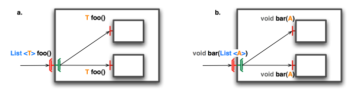
Figure 26.3. Comparison of signatures of methods between client multicast interfaces and server interfaces.
For a given multicast interface, the type of server interfaces which may be connected to it can be infered by applying the following rules: for a given multicast interface,
the server interface must have the same number of methods
for a given method method foo of the multicast interface, there must be a matching method in the server interface:
named foo
which returns:
void if the method in the multicast method returns void
T if the multicast method returns list<T>
for a given parameter List<T> in the multicast method, there must be a corresponding parameter, either List<T> or T, in the server interface, which matches the distribution mode for this parameter.
The compatibility of interface signatures is verified automatically at binding time, resulting in a documented IllegalBindingException if signatures are incompatible.
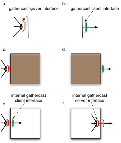
A gathercast interface transforms a list of invocations into a single invocation
A gathercast interface is an abstraction for n-to-1 communications. It handles data aggregation for invocation parameters, as well as process coordination. It gathers incoming data, and can also coordinate incoming invocations before continuing the invocation flow, by defining synchronization barriers.
Gathering operations require knowledge of the participants of the collective communication (i.e. the clients of the gathercast interface). Therefore, the binding mechanism, when performing a binding to a gathercast interface, provides references on client interfaces bound to the gathercast interface. This is handled transparently by the framework. As a consequence, bindings to gathercast interfaces are bidirectional links.
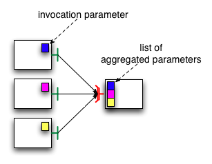
Gathercast interfaces aggregate parameters from method invocations from client interfaces into lists of invocations parameters, and they redistribute results to each client interface.
Invocation parameters are simply gathered into lists of parameters. The indexes of the parameters in the list correspond the index of the parameters in the list of connected client interfaces, managed internally by the gathercast interface.
The result of the invocation transformed by the gathercast interface is a list of values. Each result value is therefore indexed and redistributed to the client interface with the same index in the list of client interfaces managed internally by the gathercast interface.
Similarly to the distribution of invocation parameters in multicast interfaces, a redistribution function could be applied to the results of a gathercast invocation, however this feature is not implemented yet.
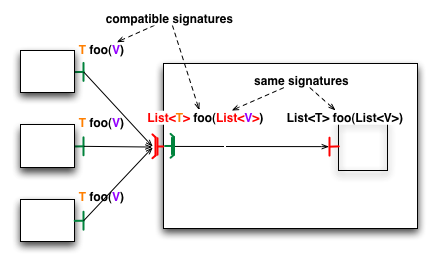
Gathercast interfaces manipulate lists of parameters
(say,
List<ParamType>
), and return lists of results (say,
List<ResultType>
). With respect to a gathercast interface, connected
client interface work with parameters which can be
contained in the lists of parameters of the methods
of the bound gathercast interface (ParamType), and
they return results which can be contained in the
lists of results of the methods of the bound
gathercast interface (ResultType).
Therefore, by analogy to the case of multicast
interfaces,
the signatures of methods differ from a
gathercast server interface to its connected
client interfaces
. This is illustrated in the following figure: the
foo method of interfaces which are client of the
gathercast interface exhibit a parameter of type
V
, the foo method of the gathercast interface
exhibits a parameter of type
List<V>
. Similarly, the foo method of client interfaces
return a parameter of type
T
, and the foo method of the gathercast interface
returns a parameter of type
List<T>
.
The compatibility of interface signatures is verified automatically at binding time, resulting in a documented IllegalBindingException if signatures are incompatible
An invocation from a client interface to a gathercast interface is asynchronous, provided it matches the usual conditions for asynchronous invocations in ProActive, however the gathercast interface only creates and executes a new invocation with gathered parameters when all connected client interfaces have performed an invocation on it.
It is possible to specify a timeout, which corresponds to the maximum amount of time between the moment the first invocation of a client interface is processed by the gathercast interface, and the moment the invocation of the last client interface is processed. Indeed, the gathercast interface will not forward a transformed invocation until all invocations of all client interfaces are processed by this gathercast interface.
Timeouts for gathercast invocations are specified by an annotation on the method subject to the timeout, the value of the timeout is specified in milliseconds:
@org.objectweb.proactive.core.component.type.annotations.gathercast.MethodSynchro(timeout=20)
If a timeout is reached before a gathercast
interface could gather and process all incoming
requests, a
org.objectweb.proactive.core.component.exceptions.GathercastTimeoutException
is returned to each client participating in the
invocation. This exception is a
runtime
exception.
It is also possible for gathercast interface not to wait for all invocations from connected client interfaces to perform an invocation by specifying the waitForAll attribute. Therefore, the gathercast interface will create and execute a new invocation on the first invocation received from any of the connected client interfaces.
Thus, this specific feature can be used by the same annotation as for the timeout but with a different attribute:
@org.objectweb.proactive.core.component.type.annotations.gathercast.MethodSynchro(waitForAll=false)
Therefore, the waitForAll attribute accepts boolean values and has for default value "true" (same behavior as if the annotation is not specified).
Furthermore, it is forbidden to combine timeout and
waitForAll set to false (an
org.objectweb.fractal.api.factory.InstantiationException
is raised) because il would be incoherent.
The API is the same for any Fractal implementation, though some classes are implementation-specific:
The fractal provider class, that corresponds to the
fractal.provider
parameters of the JVM, is
org.objectweb.proactive.core.component.Fractive
. The
Fractive
class acts as:
a bootstrap component
a GenericFactory for instantiating new components
a utility class providing static methods to create collective interfaces
As this implementation is based on ProActive, several conditions are required (more in Chapter 9, Active Objects: Creation And Advanced Concepts ):
the base class for the implementation of a primitive component has to provide a no-argument and preferably an empty constructor.
asynchronous method calls with transparent futures is a core feature of ProActive ( Section 9.7, “Asynchronous calls and futures” ), and it allows concurrent processing. Indeed, suppose a caller invokes a method on a callee. This method returns a result on a component. With synchronous method calls, the flow of execution of the caller is blocked until the result of the method called is received. In the case of intensive computations, this can be relatively long. With asynchronous method calls, the caller gets a future object and will continue its tasks until it really uses the result of the method call. The process is then blocked (it is called wait-by-necessity) until the result has effectively been calculated.
Thus, for asynchronous invocations, return types of the methods provided by the interfaces of the components have to be reifiable (Non-final and serializable class) and methods must not throw exceptions.
When a component is instantiated with the
                     					public Component newFcInstance(Type type, Object
                     					controllerDesc, Object contentDesc) throws
                     					InstantiationException
method of the
org.objectweb.fractal.api.factory.Factory
class, in addition to the type of the component have to
be specified the controller description and the content
description of the component.
The controller description (
org.objectweb.proactive.core.component.ControllerDescription
) is useful to describe the controllers of components.
It allows to define:
the name of a component.
the hierarchical type of a component.
the custom controllers for a component. The configuration of the controllers is described in a properties file whose location can be given as a parameter. The controllers configuration file is simple: it associates the signature of a controller interface with the implementation that has to be used. During the construction of the component, the membrane is automatically constructed with these controllers. The controllers are linked together, and requests targetting a control interface visit the different controllers until they find the suitable controller, and then the request is executed on this controller.
The role of the content description (
org.objectweb.proactive.core.component.ContentDescription
) is to define some informations about a component:
the classname of the component (the only one information mandatory).
the constructor parameters of the component (optional).
the activity as defined in the ProActive model (optional). See Chapter 9, Active Objects: Creation And Advanced Concepts for more informations about activity in ProActive.
the meta-object factory for the component (optional).
It is also possible to force that there is only one
instance of this component when instantiating the
component on a given multiple virtual node by using the
forceSingleInstance
method.
Collective interactions are an extension to the Fractal model, described in section Section 26.3, “Collective interfaces” , that relies on collective interfaces.
This feature provides collective interactions (1-to-n and n-to-1 interactions between components), namely gathercast and multicast interfaces
In order to define Non Functional prioritized requests (useful for instance for life cycle management, reconfiguration, ...), a partial order between each kind of request is available to specify when an incoming request can pass requests already in the queue.
Here are the different priorities availables for the requests:
F: Functional request. Always goes at the end of the requests queue.
NF1: Standard Non Functional request. Also always goes at the end of the requests queue.
NF2: Non Functional prioritized request. Pass the Functional requests into the requests queue but respect the order of the other Non Functional requests.
NF3: Non Functional most prioritized request. Pass all the other requests into the requests queue.
Thus, for prioritize non functional requests, a new
controller,
org.objectweb.proactive.core.component.controller.PriorityController
, has to be used:
public interface PriorityController {

   /**
    * All the possible kind of priority for a request on a component.
     *
    */
   public enum RequestPriority {
       /**
        * Functional priority
        */
       F,
       /**
        * Non-Functional priority
        */
       NF1,
       /**
        * Non-Functional priority higher than Functional priority (F)
        */
       NF2,
       /**
         * Non-Functional priority higher than Functional priority (F) and Non-Functional priority
        * (NF1 and NF2)
        */
       NF3;
   }

   /**
    * Set priority of all methods named 'methodName' in the interface 'interfaceName' to
    * 'priority'.
     *
    * @param interfaceName
    *            Name of the component interface providing the method
    * @param methodName
    *            Name of the method on which set the priority
    * @param priority
    *            The priority
    * @return true if success, else false
    */
   public void setPriority(String interfaceName, String methodName, RequestPriority priority);

   /**
    * Set priority of the method named 'methodName' with the signature defined by 'parametersTypes'
    * in the interface 'interfaceName' to 'priority'.
     *
    * @param interfaceName
    *            Name of the component interface providing the method
    * @param methodName
    *            Name of the method on which set the priority
    * @param parametersTypes
    *            The type of the method's parameters signature
    * @param priority
    *            The priority
    * @return true if success, else false
    */
   public void setPriority(String interfaceName, String methodName, Class<?>[] parametersTypes,
           RequestPriority priority);

   /**
    * Get the priority for a given method.
     *
    * @param interfaceName
    *            Name of the component interface
    * @param methodName
    *            Name of the method
    * @param parametersTypes
    *            The type of the method's parameters signature
    * @return
    */
   public RequestPriority getPriority(String interfaceName, String methodName, Class<?>[]
 parametersTypes);
}
Stream ports allow to ensure to have components which only have one way communication methods (client side to server side).
Thus, by using the
org.objectweb.proactive.core.component.StreamInterface
interface as a tag on the java interface definition of a
component interface, the GCM implementation will check
during the instantiation of a Fractal Interface Type
created with
createFcItfType(...)
method, if all the methods of the given interface, and
its parents, return void. If not, an exception is
thrown: "
org.objectweb.fractal.api.factory.InstantiationException
" accordingly to the Fractal specifications.
This section explains how to customize the membranes of component through the configuration, composition and creation of controllers and interceptors.
It is possible to customize controllers, by specifying a control interface and an implementation.
Controllers are configured in a simple XML configuration file, which has the following structure:
          <componentConfiguration>
            <controllers>
              <controller>
                <interface>
                  ControllerInterface
                </interface>
                <implementation>
                  ControllerImplementation
                </implementation>
              </controller>
              ...
Unless they some controllers are also interceptors (see later on), the controllers do not have to be ordered.
A default configuration file is provided, it defines the default controllers available for every ProActive component (super, binding, content, naming, lifecycle and component parameters controllers).
A custom configuration file can be specified (in this example with "thePathToMyConfigFile") for any component in the controller description parameter of the newFcInstance method from the Fractal API:
					componentInstance = componentFactory.newFcInstance(myComponentType,
												new ControllerDescription("name",myHierarchicalType,thePathToMyControllerConfigFile),
												myContentDescription);
The controller interface is a standard interface which defines which methods are available.
When a new implementation is defined for a given controller interface, it has to conform to the following rules:
The controller implementation must extend the AbstractProActiveController class, which is the base class for component controllers in ProActive, and which defines the constructor AbstractProActiveController(Component owner).
The controller implementation must override this constructor:
					public ControllerImplementation(Component owner) {
						super(owner);
					}
The controller implementation must also override the abstract method setControllerItfType(), which sets the type of the controller interface:
					protected void setControllerItfType() {
						try {
							setItfType(ProActiveTypeFactory.instance().createFcItfType(
								"Name of the controller", TypeFactory.SINGLE));
						}
						catch (InstantiationException e) {
							throw new ProActiveRuntimeException("cannot create controller type: "
								+ this.getClass().getName());
						}
					}
The controller interface and its implementation have to be declared in the component configuration file.
Controllers can also act as interceptors: they can intercept incoming invocations and outgoing invocations. For each invocation, pre and post processings are defined in the methods beforeInputMethodInvocation, afterInputMethodInvocation, beforeOutputMethodInvocation, and afterOutputMethodInvocation. These methods are defined in the interfaces InputInterceptor and OutputInterceptor, and take a MethodCall object as an argument. MethodCall objects are reified representations of method invocations, and they contain Method objects, along with the parameters of the invocation.
Interceptors are configured in the controllers XML configuration file, by simply adding input-interceptor="true" or/and output-interceptor="true" as attributes of the controller element in the definition of a controller (provided of course the specified interceptor is an input or/and output interceptor). For example a controller that would be an input interceptor and an output interceptor would be defined as follows:
          <componentConfiguration>
            <controllers>
              ...
              <controller input-interceptor="true" output-interceptor="true">
                <interface>
                  InterceptorControllerInterface
                </interface>
                <implementation>
                  ControllerImplementation
                </implementation>
              </controller>
              ...
Interceptors can be composed in a basic manner: sequentially.
For input interceptors, the beforeInputMethodInvocation method is called sequentially for each controller in the order they are defined in the controllers configuration file. The afterInputMethodInvocation method is called sequentially for each controller in the reverse order they are defined in the controllers configuration file.
If in the controller configuration file, the list of input interceptors is in this order (the order in the controller configuration file is from top to bottom):
InputInterceptor1 InputInterceptor2
This means that an invocation on a server interface will follow this path:
					--> caller --> InputInterceptor1.beforeInputMethodInvocation -->
						InputInterceptor2.beforeInputMethodInvocation --> callee.invocation -->
						InputInterceptor2.afterInputMethodInvocation -->
						InputInterceptor1.afterInputMethodInvocation
For output interceptors, the beforeOutputMethodInvocation method is called sequentially for each controller in the order they are defined in the controllers configuration file. The afterOutputMethodInvocationmethod is called sequentially for each controller in the reverse order they are defined in the
controllers configuration file.
If in the controller configuration file, the list of input interceptors is in this order (the order in the controller configuration file is from top to bottom):
OutputInterceptor1 OutputInterceptor2
This means that an invocation on a server interface will follow this path
					--> currentComponent --> OutputInterceptor1.beforeOutputMethodInvocation -->
						OutputInterceptor2.beforeOutputMethodInvocation --> callee.invocation -->
						OutputInterceptor2.afterOutputMethodInvocation -->
						OutputInterceptor1.afterOutputMethodInvocation
An interceptor being a controller, it must follow the rules explained above for the creation of a custom controller.
Input interceptors and output interceptors must implement respectively the interfaces InputInterceptor and OutputInterceptor, which declare interception methods (pre/post interception) that have to be implemented.
Here is a simple example of an input interceptor:
					public class MyInputInterceptor extends AbstractProActiveController
															implements InputInterceptor, MyController {
						public MyInputInterceptor(Component owner) {
							super(owner);
						}

						protected void setControllerItfType() {
							try {
								setItfType(ProActiveTypeFactory.instance().createFcItfType("mycontroller",
																				MyController.class.getName(),
																				TypeFactory.SERVER,
																				TypeFactory.MANDATORY,
																				TypeFactory.SINGLE));
							}
							catch(InstantiationException e) {
								throw new ProActiveRuntimeException("cannot create controller" + this
.getClass().getName());
							}
						}

						// foo is defined in the MyController interface
						public void foo() {
							// foo implementation
						}

						public void afterInputMethodInvocation(MethodCall methodCall) {
							System.out.println("post processing an intercepted an incoming functional invocation");
							// interception code
						}

						public void beforeInputMethodInvocation(MethodCall methodCall) {
							System.out.println("pre processing an intercepted an incoming functional invocation");
							// interception code
						}
					}
The configuration file would state:
          <componentConfiguration>
            <controllers>
              ...
              <controller input-interceptor="true">
                <interface>
                  MyController
                </interface>
                <implementation>
                  MyInputInterceptor
                </implementation>
              </controller>
              ...
In this implementation of the Fractal component model, Fractal components are active objects. Therefore it is possible to redefine their activity. In this context of component based programming, we call an activity redefined by a user a functional activity.
When a component is instantiated, its lifecycle is in the STOPPED state, and the functional activity that a user may have redefined is not started yet. Internally, there is a default activity which handles controller requests in a FIFO order.
When the component is started, its lifecycle goes to the STARTED state, and then the functional activity is started: this activity is initialized (as defined in InitActive), and run (as defined in RunActive).
2 conditions are required for a smooth integration between custom management of functional activities and lifecycle of the component:
the control of the request queue must use the org.objectweb.proactive.Service class
the functional activity must loop on the body.isActive() condition (this is not compulsory, but it allows to automatically end the functional activity when the lifecycle of the component is stopped. It may also be managed with a custom filter).
Control invocations to stop the component will automatically set the isActive() return value to false, which implies that when the functional activity loops on the body.isActive() condition, it will end when the lifecycle of the component is set to STOPPED.
Components running in dynamically changing execution environments need to adapt to these environments. In Fractal and GCM (Grid Component Model) component models, adaptation mechanisms are triggered by the non- functional (NF) part of the components. Interactions with execution environments may require complex relationships between controllers. In this section we focus on the adaptability of the membrane.Examples include changing communication protocols, updating security policies, or taking into account new runtime environments in case of mobile components. Adaptability implies that evolutions of the execution environments have to be detected and acted upon, and may also imply interactions with the environment and with other components for realizing the adaptation.
We provide tools for adapting controllers. These tools manage (re)configuration of controllers inside the membrane.For this, we provide a model and an implementation, using a standard component- oriented approach for both the application (functional) level and the control (NF) level. Having a component-oriented approach for the non-functional aspects also allows them to benefit from the structure, hierarchy and encapsulation provided by a component-oriented approach.
In this section, we propose to design NF concerns as compositions of components as suggested in the GCM proposal.Our general objective is to allow controllers implemented as components to be directly plugged in a component membrane. These controllers take advantage of the properties of component systems like reconfigurability, i.e. changing of the contained components and their bindings.This allows components to be dynamically adapted in order to suit changing environmental conditions. Indeed, among others, we aim at a component platform appropriate for autonomic Grid applications; those appli- cations aim to ensure some quality of services and other NF features without being geared by an external entity.
Components in the membrane introduce two major changes : first, refinements of the Fractal/GCM model concerning the structure of a membrane; second, a definition and an implementation of an API that allows GCM membranes to be themselves composed of components, possibly distributed. Both for efficiency and for flexibility reasons, we provide an implementation where controllers can either be classical objects or full components that could even be distributed. We believe that this high level of flexibility is a great advantage of this approach over the existing ones [8, 7]. Our model refinements also provide a better structure for the membrane and a better decoupling between the membrane and its externals. Finally, our approach gives the necessary tools for membrane reconfiguration, providing flexibility and evolution abilities. The API we present can be split in two parts:
Methods dedicated to component instantiation: they allow the specification of a NF type of a component, and the instantiation of NF components;
Methods for the management of the membrane: they consist in managing the content, introspecting , and managing the life-cycle of the membrane. Those methods are proposed as an extension of the Fractal component model, and consequently of the GCM;
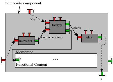
Here we present a simple example that shows the advantages of componen tizing controllers of GCM components. In our example, we are considering a naive solution for securing communications of a composite component. As described in Figure Figure 26.7, “ Example: architecture of a naive solution for secure communications ”, secure communications are implemented by three components inside the membrane: Interceptor, Decrypt, and Alert. The scenario of the example is the following: the composite component receives encrypted messages on its server functional interface. The goal is to decrypt those messages. First, the incoming messages are intercepted by the Interceptor component. It forwards all the intercepted communications to Decrypt, which can be an off-the-shelf component (written by cryptography specialists) implementing a specific decryption algorithm. The Decrypt component receives a key for decryption through the non-functional server interface of the composite (interface number 1 on the figure). If it successfully decrypts the message, the Decrypt component sends it to the internal functional components, using the functional internal client interface (2). If a problem during decryption occurs, the Decrypt component sends a message to the Alert component. The Alert component is charge to decide on how to react when a decryption fails. For example, it can contact the sender (using the non-functional client interface – 3) and ask it to send the message again. Another security policy would be to contact a “trust and reputation” authority to signal a suspicious behaviour of the sender. The Alert component is implemented by a developer who knows the security policy of the system. In this example, we have three well-identified components, with clear functionalities and connected through well-defined interfaces. Thus, we can dynamically replace the Decrypt component by another one, implementing a different decryption algorithm. Also, for changing the security policy of the system, we can dynamically replace the Alert component and change its connexions. Compared to a classical implementation of secure communications (for example with objects), using components brings to the membrane a better structure and reconfiguration possibilities. To summarize, componentizing the membrane in this example provides dynamic adaptability and reconfiguration; but also re-usability and composition from off-the-shelf components.
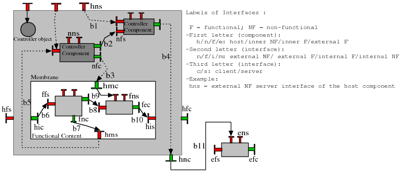
Figure Figure 26.8, “
Structure for the membrane of Fractal/GCM components
” shows the structure we suggest for the component membrane. The
membrane (in gray) consists of one object controller and two component controllers, the component controllers are connected
together and with the outside of the membrane by different bindings. For the moment, we do not specify
whether components are localized with the membrane, or distributed.
Before defining an API for managing components inside the membrane, the definition of the membrane given by the GCM specification needs some refinements. Those refinements, discussed in this section, provide more details about the structure a membrane can adopt. Figure Figure 26.8, “ Structure for the membrane of Fractal/GCM components ” represents the structure of a membrane and gives a summary of the different kinds of interface roles and bindings a GCM component can provide. As stated in the GCM specification, NF interfaces are not only those specified in the Fractal specification, which are only external server ones. Indeed, in order to be able to compose NF aspects, the GCM requires the NF interfaces to share the same specification as the functional ones: role, cardinality, and contingency. For example, in GCM, client NF interfaces allow for the composition of NF aspects and reconfigurations at the NF level. Our model is also flexible, as all server NF interfaces can be implemented by both objects or components controllers.
All the interfaces showed in Figure Figure 26.8, “ Structure for the membrane of Fractal/GCM components ” give the membrane a better structure and enforce decoupling between the membrane and its externals. For example, to connect nfc with fns, our model adds an additional stage: we have first to perform binding b3, and then binding b9. This avoids nfc to be strongly coupled with fns: to connect nfc to another fns, only binding b9 has to be changed. In Figure Figure 26.8, “ Structure for the membrane of Fractal/GCM components ”, some of the links are represented with dashed arrows. Those links are not real bindings but “alias” bindings (e.g. b3); the source interface is the alias and it is “merged” with the destination interface. These bindings are similar to the export/import bindings existing in Fractal (b6, b10) except that no interception of the communications on these bindings is allowed.
While componentizing the membrane clearly improves its programmability and its capacity to evolve, one can wonder what happens to performance. First, as our design choice allows object controllers, one can always keep the efficiency of crucial controllers by keeping them as objects. Second, the overhead for using components instead of objects is very low if the controllers components are local, and are negligible compared to the communication time, for example. Finally, if controllers components are distributed, then there can be a significant overhead induced by the remote communications, but if communications are asynchronous, and the component can run in parallel with the membrane, this method can also induce a significant speedup, and a better availability of the membrane. To summarize, controllers invoked frequently and performing very short treatments, would be more efficiently implemented by local objects or local components. For controllers called less frequently or which involve long computations, making them distributed would improve performances and availability of the membrane.
To typecheck bindings between membranes, we have to extend the GCM model with a new concept: the non-functional type of a component. This type is defined as the union of the types of NF interfaces the membrane exposes. To specify the NF type of a component, we propose to overload the Fractal newFcInstance method (the one to create functional components) as follows:
										public Component newFcInstance(Type fType,Type nfType, any contentDesc, any
 controllerDesc);
In this method, nfType represents the NF type of the component; it can be specified by hand. Of course the standard Fractal type factory has to be extended in order to support all possible roles of NF interfaces. Soon, it should be possible to specify the NF type within a configuration file: the controller descriptor argument (controllerDesc) can be a file written in Architecture Description Language (ADL) containing the whole description of the NF system.
Components inside the membrane are non-functional components. They are similar to functional ones. However, their purpose is different because they deal with NF aspects of the host component. Thus, in order to enforce separation of concerns, we restrict the interactions between functional and NF components. For example, a NF component cannot be included inside the functional content of a composite. Inversely, a functional component cannot be added inside a membrane. As a consequence, direct bindings between functional interfaces of NF and functional components are forbidden. To create NF components, we extend the common Fractal factories (generic factory and ADL factory). For generic factory, we add a method named newNFcInstance that creates this new kind of components:
										public Component newNFcInstance(Type fType,Type nfType, any contentDesc, any
 controllerDesc);
Parameters of this method are identical to its functional equivalent and NF components are created the same way as functional ones.
										public void addNFSubComponent(Component component) throws IllegalContentException;
										public void removeNFSubComponent(Component component) throws IllegalContentException,
 IllegalLifeCycleException, NoSuchComponentException;
										public Component[] getNFcSubComponents();
										public Component getNFcSubComponent(string name) throws NoSuchComponentException;
										public void setControllerObject(string itf, any controllerclass) throws
 NoSuchInterfaceException;
										public void startMembrane() throws IllegalLifeCycleException;
										public void stopMembrane() throws IllegalLifeCycleException;
Figure 26.9. The primitives for managing the membrane.
To manipulate components inside membranes, we introduce primitives to perform basic operations like adding, removing
or getting a reference on a NF component.
We also need to perform calls on well-known Fractal controllers (life-cycle controller, binding controller, . . .
)
of these components. So, we extend Fractal/GCM specification by adding
a new controller called membrane controller. As we want it to manage all the controllers, it is the only mandatory
controller that has to belong to any
membrane. It allows the manual composition of membranes by adding the
desired controllers. The methods presented in Figure Figure 26.9, “
The primitives for managing the membrane.
” are included in the
MembraneController interface; they are the core of the API and are sufficient
to perform all the basic manipulations inside the membrane. They add, remove,
or get a reference on a NF component. They also allow the management of ob-
ject controllers and membrane’s life-cycle. Referring to Fractal, this core API
implements a subset of the behavior of the life-cycle and content controllers
specific to the membrane. This core API can be included in any Fractal/GCM
implementation. Reconfigurations of NF components inside the membrane are
performed by calling standard Fractal controllers. The general purpose API
defines the following methods:
addNFSubComponent(Component component): adds the NF component given as argument to the membrane;
removeNFSubComponent(Component component): removes the specified component from the membrane;
getNFcSubComponents(): returns an array containing all the NF components;
getNFcSubComponent(string name): returns the specified NF component, the string argument is the name of the component;
setControllerObject(string itf, any controllerclass): sets or replaces an existing controller object inside the membrane. Itf specifies the name of the control interface which has to be implemented by the controller class, given as second parameter. Replacing a controller object at runtime provides a very basic adaptivity of the membrane;
startMembrane(): starts the membrane, i.e. allows NF calls on the host component to be served. This method can adopt a recursive behavior, by starting the life-cycle of each NF component inside the membrane;
stopMembrane(): Stops the membrane, i.e. prevents NF calls on the host component from being served except the ones on the membrane controller. This method can adopt a recursive behavior, by stopping the life-cycle of each NF component.
										public void bindNFc(String clientItf, String serverItf) throws NoSuchInterfaceException,
 IllegalLifeCycleException,IllegalBindingException, NoSuchComponentException;
										public void bindNFc(String clientItf, Object serverItf) throws NoSuchInterfaceException,
 IllegalLifeCycleException,IllegalBindingException, NoSuchComponentException;
										public void unbindNFc(String clientItf) throws NoSuchInterfaceException,
 IllegalLifeCycleException, llegalBindingException, NoSuchComponentException;
										public String[] listNFc(String component) throws NoSuchComponentException;
										public Object lookupNFc(String itfname) throws
 NoSuchInterfaceException,NoSuchComponentException;
										public void startNFc(String component) throws IllegalLifeCycleException,
 NoSuchComponentException;
										public void stopNFc(String component) throws IllegalLifeCycleException,
 NoSuchComponentException;
										public String getNFcState(String component) throws NoSuchComponentException;
Figure 26.10. Higher level API
In Figure Figure 26.10, “ Higher level API ”, we present an alternative API, that addresses NF components by their names instead of their references. These methods allow to make calls on the binding controller and on the life-cycle controller of NF components that are hosted by the component membrane. Currently, they don’t take into account the hierarchical aspect of NF components. The method calls address the NF components and call their controllers at once. For example, here is the Java code that binds two components inside the membrane using the general purpose API. It binds the interface “i1” of the component “nfComp1” inside the membrane to the interface “i2” of the component “nfComp2”. Suppose mc is a reference to the MembraneController of the host component.
										Component nfComp1=mc.getNFcSubComponent("nfComp1");
										Component nfComp2=mc.getNFcSubComponent("nfComp2");
										Fractal.getBindingController(nfComp1).bindFc("i1",nfComp2.getFcInterface("i2"));
Using the API of Figure Figure 26.10, “ Higher level API ”, this binding can be realized by the following code, that binds the component “nfComp1” correctly.
mc.bindNFc("nfComp1.i1","nfComp2.i2");
Similarly to the example above, all the methods of Figure Figure 26.10, “ Higher level API ” result in calls on well-known Fractal controllers. Interfaces are represented as strings of the form component.interface, where component is the name of the inner component and interface is the name of its client or server interface. We use the name “mem- brane” to represent the membrane of the host component, e.g. membrane.i1 is the NF interface i1 of the host component; in this case interface is the name of an interface from the NF type. For example, bindNFc(string, string) allows to perform the bindings: b1, b2, b4, b3, b9, b7 and b5 of Figure Figure 26.8, “ Structure for the membrane of Fractal/GCM components ”.
The API presented in Figure Figure 26.10, “ Higher level API ” introduced higher level mechanisms for reconfiguring the membrane. It also solves the problem of local components inside the membrane. As usual in distributed programming paradigms, GCM objects/components can be accessed locally or remotely. Remote references are accessible everywhere, while local refer- ences are accessible only in a restricted address space. When returning a local object/component outside its address space, there are two alternatives: create a remote reference on this entity; or make a copy of it. When considering a copy of a NF local component, the NF calls are not consistent. If an invocation on getNFcSubComponent(string name) returns a copy of the specified NF component, calls performed on this copy will not be performed on the “real” NF component inside the membrane. Methods introduced in Figure Figure 26.10, “ Higher level API ” solve this problem.
Communications between components in a hierarchical model may involve the crossing of several membranes, and therefore paying the cost of several indirections. If the invocations are not intercepted in the membranes, then it is possible to optimize the communication path by shortcutting: communicating directly from a caller component to a callee component by avoiding indirections in the membranes.
In the Julia implementation, a shortcut mechanism is provided for components in the same JVM, and the implementation of this mechanism relies on code generation techniques.
We provide a shortcut mechanism for distributed components, and the implementation of this mechanism relies on a "tensioning" technique: the first invocation determines the shortcut path, then the following invocations will use this shortcut path.
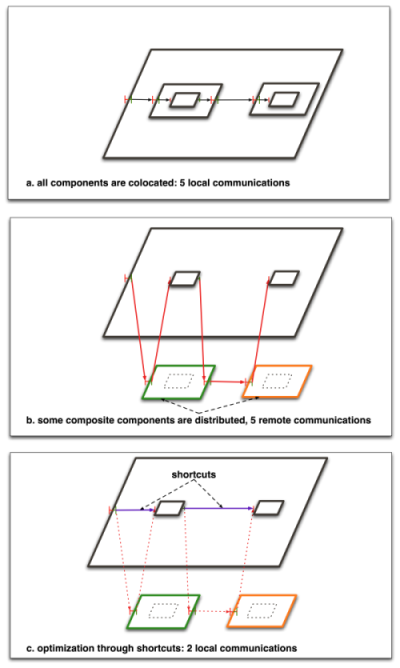
For example, in the following figure, a simple component system, which consists of a composite containing two wrapped primitive components, is represented with different distributions of the components. In a, all components are located in the same JVM, therefore all communications are local communications. If the wrapping composites are distributed on different remote JVMs, all communications are remote because they have to cross composite enclosing components. The short cut optimization is a simple bypassing of the wrapper components, which results in 2 local communications for the sole functional interface.
Shortcuts are available when composite components are synchronous components (this does not break the ProActive model, as composite components are structural components). Components can be specified as synchronous in the ControllerDescription object that is passed to the component factory:
					ControllerDescription controllerDescription = new ControllerDescription("name",
 Constants.COMPOSITE,
																									Constants.SYNCHRONOUS);
When the system property proactive.components.use_shortcuts is set to true, the component system will automatically establish short cuts between components whenever possible.
© 1997-2008 INRIA Sophia Antipolis All Rights Reserved