USB On-The-Go (OTG) Technology Guide
This document introduces the USB On-The-Go technology.
Purpose
The USB OTG technology enables a USB device to swap roles (from host to peripheral and from peripheral to host) dynamically in relation to another USB device.
Intended Audience:
This document is intended for developers who are implementing USB OTG services on a Symbian platform phone.
Understanding USB On-The-Go
This document contains information on the following topics:
Universal Serial Bus (USB) is a well established technology in the personal computing domain. It was originally designed to enable users of desktop or laptop computers (which are known in USB terminology as "hosts") to attach their computers easily to a wide range of peripherals. Hosts generally have much more computing power than peripherals; therefore the USB standard puts them in control of communications on the USB link and they then make use of services that are passively offered by the peripheral.
Mobile phones have traditionally been viewed as peripherals: when a mobile phone is attached to a USB host it can provide a wide range of services, including internet connectivity, mass storage services, and synchronisation of contact lists and calendars.
However, as the computing power and complexity of mobile devices has increased, mobile phones (and other mobile devices, for example, digital cameras) have themselves become sufficiently powerful to make use of other peripherals while still needing to retain the capability to act as USB peripherals themselves.
Therefore the USB Implementers Forum has defined a combination of hardware designs and software protocols to allow mobile devices to be created that perform this dual role. (The designs and protocols are defined in a document called the On-The-Go Supplement to the USB 2.0 Specification.)
The result is that it is now possible for a USB device to present itself through a single receptacle to another USB device as either a host or a peripheral (although, importantly, not as both at once).
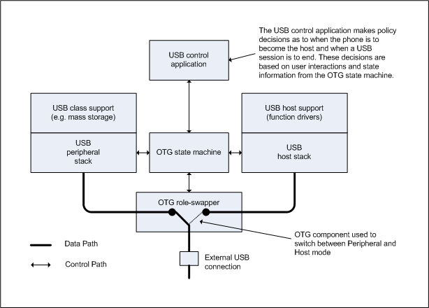
The logical components inside an OTG device are summarized in the diagram above. As you can see, an OTG device will contain two USB protocol stacks, one for when it is acting as a peripheral and one for when it is acting as a host. Between these two stacks are software components (the OTG state machine and role-swapper) that control which of these two stacks is operating at a given time.
Plugs, receptacles and cables for OTG devices
Before OTG, the USB specification defined two matching receptacle and plug pairs: the A-plug and A-receptacle, and the B-plug and B-receptacle. The A-plug only fitted into an A-receptacle, and the B-plug only fitted into a B-receptacle; the USB cable was terminated at one end with an A-plug and at the other with a B-plug; and USB hosts presented an A-receptacle while USB peripherals presented a B-receptacle.
This arrangement ensured that there was no opportunity to connect a host to another host, or a peripheral to another peripheral. It also created a fixed association between the USB host and the A-receptacle, and between the USB peripheral and the B-receptacle.
OTG has complicated this simple arrangement. It has also reduced the size of the connectors to make them more suitable to fit on mobile devices.
The set of available connectors defined in the main USB specification is now as follows:
A-plug and A-receptacle
B-plug and B-receptacle
Mini-B plug and Mini-B receptacle (these are simply smaller versions of the B-plug and receptacle)
And the following connectors have now also been added by the OTG supplement:
Micro-A plug cables still adhere to the rule that one end has an A-plug (or Micro-A plug) while the other end has a B-plug (or a Mini- or Micro-B plug).
The Micro AB-receptacle is a key feature of an OTG device. It will accept either a Micro-A plug or a Micro-B plug, and indicates that the device it is presented by is dual-role (in other words, that it can operate either as a USB Host or a USB peripheral).
A device presenting a Micro-AB receptacle with a Micro-A plug inserted is known as an "A-device".
A device presenting a Micro-AB receptacle without a Micro-A plug inserted is known as a "B-device".
Note: a B-device is defined by the absence of an A-plug and remains a B-device whether a B-plug is inserted or not.
Signalling and power distribution over USB
You need to have some understanding of the wiring within a USB cable and its connector in order to understand the protocols used in USB in general and in OTG in particular.
A USB cable contains four lines and each has a different designation:
These lines form the basis of the electrical connection between two connected USB devices; signalling performed by a device at one end of the USB cable can be detected on the lines by the device at the other end of it (although note that the Gnd line is not used for signalling).
The particular meanings (for USB and OTG communication) of the signals on the different lines are given in the table below.
| USB cable line | Used for data transfers | Used for supplying power | Used for communication signalling |
|---|---|---|---|
D+ |
Yes (in combination with D-) |
No |
Yes (when VBus is powered, the D+ line is used by a peripheral to indicate its presence to a host. The D+ line may also used in SRP signalling) |
D- |
Yes (in combination with D+) |
No |
No |
VBus |
No |
Yes (the VBus is line is used by an A-device to provide power - some of the time - to a B-device) |
Yes (the VBus line used by an A-device to signal its presence to a B-device. The VBus line may also be used in SRP signalling) |
The Micro-A plug and Micro-B plug present four pins, representing D+, D-, VBus and Gnd; they also present a fifth pin known as ID.
The ID pin does not correspond to a wire running the length of the cable but is instead connected to the Gnd pin (in the case of a Micro-A plug), or not connected to anything (in the case of a Micro B-plug). The differing electrical resistance of the ID pin in the Micro-A and Micro-B plugs allows the transceiver attached to the Micro-AB receptacle to determine whether or not an A-plug is present. It is on this basis that an OTG device decides whether it is currently an A-device or a B-device.
Even though USB OTG devices can operate as both hosts and peripherals, the distinction between the A- and B-device remains important for two reasons:
The A-device always powers VBus
However, unlike a traditional USB host, an OTG A-device is not required to power VBus at all times (even though no USB traffic is possible while VBus is not powered). This is because an OTG device is likely to be battery powered and its designers will not want to drain its batteries unnecessarily (for example, when USB is not in use). In USB terminology, a continuous period where VBus is powered by the A-device is known as a "session".
The A-device always starts off as the USB host
At the start of a session, the A-device is responsible for acting as the USB host. Later in the same session, it can act as a USB peripheral (without the USB cable being physically swapped round) because USB OTG supplement defines two protocols by means of which the host role can be swapped from device to device (see next section).
The USB OTG supplement defines two protocols, Host Negotiation Protocol (HNP) and Session Request Protocol (SRP), which facilitate role-swapping between devices.
Session Request Protocol (SRP)
Because an A-device is not required to power VBus continuously, it is possible for two OTG devices to be physically connected to each other by a USB cable but for no USB session to exist between them.
The designers of OTG realised that, when the two devices were in this situation, the B-device would be unable to detect the A-device (because VBus would not be powered), and the A-device would be unable to detect the B-device (because a B-device does not have a connection to an A-device if VBus is not powered).
Now, although a user interaction with the A-device could trigger the A-device to power VBus and thereby discover the B-device, no equivalent mechanism existed by which the B-device could re-store USB connectivity with the A-device on its own initiative: if the user interacted with the B-device, the B-device could not power VBus and thereby discover the A-device, because VBus cannot be powered by a B-device.
The solution that the designers of OTG arrived at was the Session Request Protocol (SRP).
SRP is a protocol that can only be initiated by a B-device and only when VBus is not powered. Because the B-device cannot know while VBus is low whether there is an A-device attached, the B-device sends out an SRP signal speculatively. If an A-device is attached, the A-device will detect the SRP signalling and power up VBus. Once VBus is powered, the A-device and B-device are able to communicate normally.
Host Negotiation Protocol (HNP)
As described above, an OTG dual-role device can act as a USB host or peripheral but not as both simultaneously. When two OTG dual-role devices are connected together, the orientation of the USB cable defines each device’s initial role: the A-Device operates as the host, and the B-Device operates as the peripheral.
One of the goals of the OTG designers was to enable these roles to be swapped between dual-role devices without the USB cable needing to be removed. They therefore defined two new operational states, B-host and A-peripheral, and defined a protocol to handle the swapping of the host role back and forth between two dual role devices. This protocol is called HNP.
A dual-role OTG B-device must advertise to a host that it can initiate and respond to the HNP protocol. The B-device does this by including a special OTG descriptor (which contains a flag indicating the device's support for HNP) in the bundle of descriptors it returns to the host during enumeration. A non-OTG host will ignore this descriptor, but an OTG A-host will recognise the descriptor and determine that the B-device does support HNP.
Once the A-host has determined that the B-device does support HNP, the A-host will send a SetFeature request to set the b_hnp_enable feature. At this point, the B-peripheral can determine that the host it is connected to is also dual-role and therefore that it also supports HNP.
When the A-host device no longer needs to use the B-peripheral device, it stops any further data traffic being sent to the B-peripheral, thereby causing the B-peripheral to enter the "suspended" state. When the B-peripheral is suspended and b_hnp_enable has been set, the B-peripheral is allowed to initiate the HNP protocol.
To do this, the B-device "disconnects" from the A-host by manipulating the signal on the D+ line. The A-device then detects this disconnection and "connects" itself back to the B-device, again by manipulating the signal on the D+ line. Finally, the B-device detects this connection and HNP is complete.
The B-Device is now able to act as host (B-host) and the A-device must respond to it as a peripheral (A-peripheral). The same HNP protocol is triggered automatically when the B-host eventually suspends the A-peripheral to swap roles back in the opposite direction. Roles may swap any number of times during the same session.
Tutorials
For information about using the Symbian library that provides an interface to the Symbian OTG stack, see The USB Manager Library.