Color Correction Curves
Color Correction Curves make color adjustments using curves for each color channel. Depth based adjustments allow you to vary the color adjustment according to a pixel’s distance from the camera. For example, objects on a landscape typically get more desaturated with distance due to the effect of particles in the atmosphere scattering.
Selective adjustments can also be applied, so you can swap a target color in the scene for another color of your own choosing.
Lastly, Saturation is an easy way to adjust all color saturation or desaturation (until image turns black & white) which is an effect that is not achievable with curves only.
See also the new Color Correction Lookup Texture Effect for lookup texture based color grading.
The following images demonstrate how by simply enhancing the saturation slider and the blue channel curve can make a scene drastically different
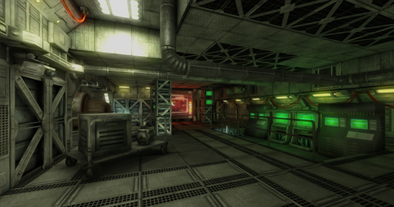
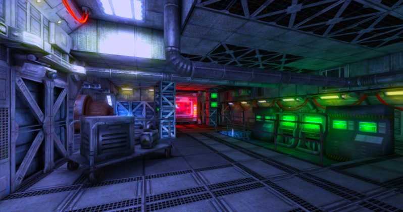
As with the other image effects, you must have the Standard Assets Effects package installed before it becomes available.
Properties
| Property: | Function: |
|---|---|
| Mode | Chose between advanced or simple configuration modes. |
| Saturation | Saturation level (0 creates a black & white image). |
| Red | The red channel curve. |
| Green | The green channel curve. |
| Blue | The blue channel curve. |
| Red (Depth) | The red channel curve for depth based correction. |
| Green (Depth) | The green channel curve for depth based correction. |
| Blue (Depth) | The blue channel curve for depth based correction. |
| Blend Curve | Defines how blending between the foreground and background color correction is performed. |
| Selective Color Correction | |
| Enable | Enables the optional selective color correction. |
| Key | The key color for selective color correction. |
| Target | The target color for selective color correction. |
Understanding Curves
Curves offer a powerful way to enhance an image and can be used to increase or decrease contrast, add a tint or create psychedelic color effects. Curves work on each of the red, green and blue color channels separately and are based around the idea of mapping each input brightness level (ie, the original brightness value of a pixel) to an output level of your choosing. The relationship between the input and output levels can be shown on a simple graph:-
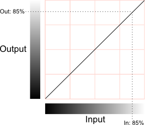
The horizontal axis represents the input level and the vertical represents the output level. Any point on the line specifies the output value that a given input is mapped to during processing. When the “curve” is the default straight line running from bottom-left to top-right, the input value is mapped to an identical output value, which will leave the pixel unchanged. However, the curve can be redrawn to re-map the brightness levels as required. A simple example is when the line goes diagonally from top-left to bottom-right:-
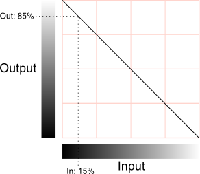
In this case, the pixel’s brightness will be inverted; 0% will map to 100%, 25% to 75% and vice versa. If this is applied to all color channels then the image will be like a photographic negative of the original.
Contrast
Most of the detail in an image is conveyed by the difference in brightness levels between pixels, regardless of their colour. Pixels that differ by less than about 2% brightness are likely to be indistinguishable but above this, the greater the difference, the greater the impression of detail. The spread of brightness values in the image is referred to as its contrast.
If a shallow slope is used for the curve, rather than the corner-to-corner diagonal then the full range of input values will be squeezed into a narrower range of output values:-
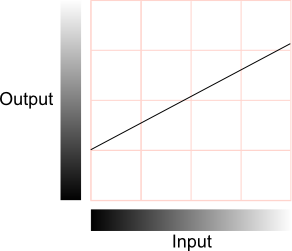
This has the effect of reducing the contrast, since the differences between pixel values in the output are necessarily smaller than those in the input (indeed, two slightly different input values may actually get mapped to the same output value). Note that since the image no longer spans the full range of output values, it is possible to slide the curve up and down the range, resulting in an image which is brighter or darker overall (the average brightness is sometimes called the “sit” point and is the parameter adjusted by the brightness control on a TV set). Reduced contrast can give the impression of gloom, fog or a dazzling light source in a scene, depending on the overall brightness.
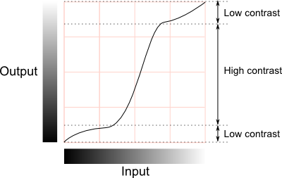
It is not necessary to reduce the contrast across the whole range of brightness levels. The curve’s slope can vary along its length, with the shallower parts corresponding to ranges of reduced contrast. In between the shallow parts, the slope may be steeper than the default, and the contrast will actually increase in these ranges. Changing the curve like this gives a useful way to increase contrast in some parts of the image while reducing it in areas where the detail is less important:-
Colour Effects
If the curves are set identically for each color channel (red, green and blue) then the changes will mainly affect the brightness of pixels while their colors remain relatively unchanged. However, if the curves are set differently for each channel then the colors can change dramatically. Many complex interactions between the color channels are possible but some basic insight can be gained from the following diagram:-
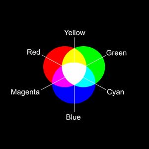
As explained in the section above, a reduction of contrast can accompany an increase or reduction in the overall brightness. If, say, the red channel is brightened then a red tint will be visible in the image. If it is darkened then the image will be tinted towards cyan (since this color is obtained by combining the other two primaries, green and blue).
Depth-Based Color Correction
Colors often appear slightly different when viewed at a distance. For example, in a landscape scene, colors tend to get desaturated by atmospheric light scattering. This kind of effect can be created using depth-based color correction. When this is enabled, two sets of color curves become available, one for the camera’s near clipping plane and the other for the far clipping plane. The actual correction applied to an object depends on its distance from the camera; the normalized distance between the two clipping planes is used as an interpolation parameter between the two sets of color curves. The exact type of interpolation is specified by an additional blending curve, which maps the normalised distance to an interpolation value in much the same way that a color curve maps an input to an output. By default, this curve is a straight diagonal which results in linear interpolation between the two color corrections. However, it can be modified to bias the correction according to distance.
Selective Color Correction
Using this setting, it is possible to replace a particular color in the original image (referred to as the “key”) and replace it with a chosen target color. Using a single exact color for the key would tend to introduce visual artifacts and so a range is used instead. The resulting color is an interpolation between the key and target colors, depending on how close the original image pixel is to the specified key color.
Editing Curves
Clicking on one of the curves in the inspector will open an editing window:-
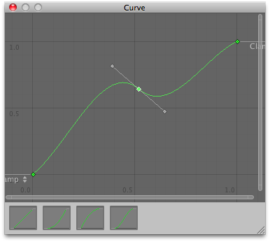
At the bottom of the window are a number of presets for common curves. However, you can also alter the curve by manipulating the key points. Right clicking on the curve line will add a new key point which can be dragged around with the mouse. If you right click on one of the points, you will see a contextual menu that gives several options for editing the curve. As well as allowing you to delete the key, there are four options that determine how it will affect the shape of the curve:-
Auto: the curve will pass through the point and its shape will be adjusted to keep the curvature smooth between neighbouring points.
Free Smooth: the tangent of the curve can be edited using handles attached to the key point.
Flat: Free Smooth mode is enabled and the tangent is set horizontally.
Broken: The key point has tangent handles as with Free Smooth mode but the handles on the left and right of the curve can be moved separately to create a sharp break rather than a smooth curve.
Below these options are a few settings that control how a point’s tangent handles behave:-
Free: Broken mode is enabled for the curve at the specified tangent.
Linear: The curve between the key point and its neighbour is set to a straight line.
Constant: A flat horizontal line is drawn from the curve to its neighbour and the vertical displacement occurs as a sharp step.
Hardware Support
This effect requires a graphics card that supports Depth Textures. See the Graphics Hardware Capabilities and Emulation page for further details and a list of compliant hardware.