Relevant to Blender v2.36
When working with geometric objects in Blender, you can work in two modes: ObjectMode and EditMode. Basically, as seen in the previous section, operations in ObjectMode affect whole objects, and operations in EditMode affect only the geometry of an object, but not its global properties such as the location or rotation.
In Blender you switch between these two modes with the TAB
key. EditMode only works on one object at a time: the active object.
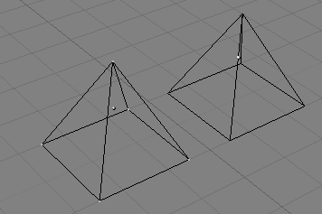
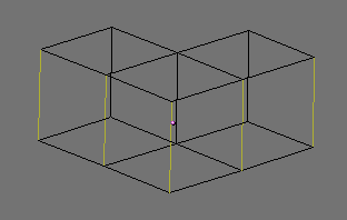
An object outside EditMode is drawn in purple in the 3D Windows
(in wireframe mode) when selected; it is black otherwise. The active object
is drawn black in EditMode, but each vertex is highlighted in purple
(Figure 6.2, “Two pyramids, one in EditMode (left) and one in ObjectMode
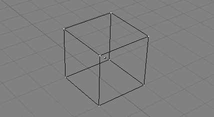
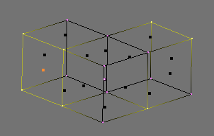
(right).”). Selected vertices are drawn in yellow
(Figure 6.3, “Cube with selected vertices in yellow. ”) and, if appropriate buttons in
the Editing (F9) Context Mesh Tools 1 Panel are
pressed (Draw Faces and Draw Edges)
also selected edges and faces are highlighted.
In basic meshes, everything is built from three basic structures: Vertices, Edges and Faces. (We're not talking about Curves, NURBS, and so forth here.) But there is no need to be disappointed: This simplicity still provides us with a wealth of possibilities that will be the foundation for all our models.
Vertices
A vertex is primarily a single point or position in 3D space. It is usually invisible in rendering and in ObjectMode. (Don't mistake the center point of an object for a vertex. It looks similar, but its bigger and you can't select it.)
To create a new vertex, change to EditMode, hold down CTRL, and click with the LMB. Of course, as a computer screen is two-dimensional, Blender can't determine all three vertex coordinates from one mouse click, so the new vertex is placed at the depth of the 3D cursor 'into' the screen. Any vertices selected previously are automatically connected to the new one with an edge.
Edges
An edge always connects two vertices with a straight line. The edges are the 'wires' you see when you look at a mesh in wireframe view. They are usually invisible on the rendered image. They are used to construct faces. Create an edge by selecting two vertices and pressing FKEY.
Faces
A Face is the most high level structure in a mesh. Faces are used to build the actual surface of the object. They are what you see when you render the mesh. A Face is defined as the area between either three or four vertices, with an Edge on every side. Triangles always work well, because they are always flat and easy to calculate.
Take care when using four-sided faces, because internally they are simply divided into two triangles each. Four-sided faces only work well if the Face is pretty much flat (all points lie within one imaginary plane) and convex (the angle at no corner is greater than or equal to 180 degrees). This is the case with the faces of a cube, for example. (That's why you can't see any diagonals in its wireframe model, because they would divide each square face into two triangles. While you could build a cube with triangular faces, it would just look more confusing in EditMode.)
An area between three or four vertices, outlined by Edges, doesn't have to be a face. If this area does not contain a face, it will simply be transparent or non-existent in the rendered image. To create a face, select three or four suitable vertices and press FKEY.
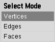
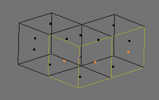
In EditMode there are three different selection modes.
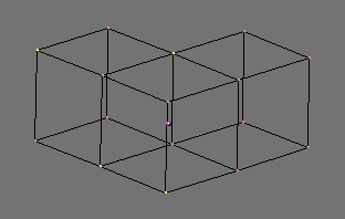
Verticesmode. Press CTRL-TAB and select Vertices from menu. The selected vertices are drawn in yellow and unselected ones have a pink color.Edgesmode. Press CTRL-TAB and select Edges from menu. In this mode the vertices are not drawn. Instead the selected edges are drawn in yellow and unselected edges have a black color.Facesmode. Press CTRL-TAB and select Faces from menu. In this mode the faces are drawn with a selection point in the middle which is used for selecting a face. Selected faces are drawn in yellow with the selection point in orange, unselected faces are drawn in black.
See Figure 6.4, “EditMode selection menu.” for menu.
Almost all modification tools are availiable in all three modes. So you can
Rotate, Scale and Extrude
etc. in all modes. Of course rotating and scaling a single
vertex will not do anything useful, so some tools are more or less applicable in some modes.
You can also enter the different modes by selecting one of the three buttons in the toolbar. See Figure 6.5, “EditMode selection buttons. Vertices, Edges and Faces modes from left to right.”. Using the buttons you can also enter mixed modes by SHIFT-LMB clicking the buttons.
Note
The Mode Selection buttons are only visible in EditMode.
When switching modes, from Vertices to Edges
and from Edges to Faces, the selected parts will
still be selected if they form a complete set in the new mode. For example, if all four edges
in a face are selected, switching from Edges mode to Faces
mode will keep the face selected. All selected parts that do not form a complete set in the new
mode will be unselected.
See Figure 6.6, “Vertex mode example.”, Figure 6.7, “Edge mode example.”, Figure 6.8, “Face mode example.” and Figure 6.9, “Mixed mode example.” for examples of the different modes.

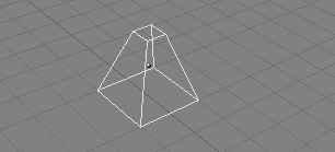
Most simple operations from ObjectMode (like selecting, moving, rotating, and scaling) work identically on vertices as they do on objects. Thus, you can learn how to handle basic EditMode operations very quickly. The only notable difference is a new scaling option, ALT-S which scales the selected vertices along the direction of the normals (shrinks-fattens). The truncated pyramid in Figure 6.10, “Chopped-off pyramid”, for example, was created with the following steps:
Add a cube to an empty scene. Enter EditMode.
Make sure all vertices are deselected (purple). Use border select (BKEY) to select the upper four vertices.
Check that the scaling center is set to anything but the 3D cursor (see Figure 5.1, “The rotation point selection buttons”), then switch to scale mode (SKEY), reduce the size, and confirm with LMB.
Exit EditMode by pressing TAB.
One extra feature for EditMode is the Mirroring tool. If you have some vertices selected and you press MKEY you will be presented with a Menu containing nine options. You can select from these to mirror the selected vertices with respect to any of the X, Y or Z axes of the Global, Local, or Viewing reference.
One additional feature of EditMode is the CircleSelect mode. It is invoked by pressing BKEY twice instead of only once, as you would for BorderSelect. A light grey circle is drawn around the cursor and any LMB click selects all vertices within. NUM+ and NUM- or the MW, if any, enlarge or shrink the circle.
All operations in EditMode are ultimately performed on the vertices; the connected edges and faces automatically adapt, as they depend on the vertices' positions. To select an edge, you must select the two endpoints or either place the mouse on the edge and press CTRL-ALT-RMB. To select a face, each corner must be selected.
EditMode operations are many, and most are summarized in the
Editing Context Buttons window, accessed via the (
 )
header button or via F9
(Figure 6.11, “Edit Context.”). Note the group
of buttons in the
)
header button or via F9
(Figure 6.11, “Edit Context.”). Note the group
of buttons in the Mesh Tools 1 Panel:
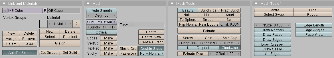
NSize:- Determines the length, in Blender Units, of the normals to the faces, if they are drawn.Draw Normals- Toggle drawing of Normals. If this is ON, face normals are drawn as cyan segments.Draw Faces- If this is ON, faces are drawn as semi-transparent blue, or as semi-transparent purple if they are selected. If this is OFF, faces are invisible.Draw Edges- Edges are always drawn black, but if this button is ON, selected edges are drawn in yellow. Edges joining a selected node and an un-selected one have a yellow-black gradient.Draw Creases- If this is selected the edges, with creasing other than zero, a part of the edge will be drawn with a thicker line. See the section called “Weighted creases for subdivision surfaces”Draw Seams- If this is selected the edges, with a marked seam, will be drawn with an orange color. See link: TBDAll Edges- Only those edges strictly necessary to show an object's shape are shown in Object mode. You can force Blender to draw all edges with this button.Edge Length- If this is selected the length, in Blender units, will be drawn near the center of the selected edge.Edge Angles- If this is selected the angle, in degrees, will drawn near the corner of two selected edges. The edges must be connected to same corner.Face Area- If this is selected the area, in Blender units, will be drawn near the center of the selected face.
Note
Of course, all these colors are customizable in the Theme editor.
With WKEY you can call up the "Specials" menu in EditMode (Figure 6.12, “Specials Menu.”). With this menu you can quickly access functions which are frequently required for polygon-modelling.
Tip
You can access the entries in a PopupMenu by using the corresponding numberkey. For example, pressing WKEY and then 1KEY will subdivide the selected edges without you having to touch the mouse at all.
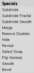
Subdivide- Each selected edge is split in two, new vertices are created at middle points, and faces are split too, if necessary.Subdivide Fractal- As above, but new vertices are randomly displaced within a user-defined range.Subdivide Smooth- As above, but new vertices are displaced towards the barycenter (centre of mass) of the connected vertices.Merge- Merges selected vertices into a single one, at the barycenter position or at the cursor position.Remove Doubles- Merges all of the selected vertices whose relative distance is below a given threshold (0.001 by default).Hide- Hides selected vertices.Reveal- Shows hidden vertices.Select Swap- All selected vertices become unselected and vice-versa.Flip Normals- Change the Normal directions in the selected faces.Smooth- Smooths out a mesh by moving each vertex towards the barycenter of the linked vertices.Bevel- Bevels the entire object regardless of the selected vertices, edges or faces. See the section called “Bevelling Tools”
Many of these actions have
a button of their own in the Mesh Tools Panel of the
Edit Buttons Window
(Figure 6.11, “Edit Context.”). The Remove
doubles threshold can be adjusted here, too.
Blender has a global undo system, giving full multiple level undo capabilities in all areas of Blender. Exceptions are: Edit mode Armature, and Fileselect, Audio and Oops windows.
The new global hotkey for undo is CTRL-Z, and CTRL-SHIFT-Z for redo.
Mesh undo works in the background saving copies of your mesh in memory as you make changes. Pressing the UKEY in mesh EditMode reverts to the previously saved mesh, undoing the last edit operation (Figure 6.13, “Undo and Redo”).
Undo operations are only stored for one mesh at a time. You can leave and re-enter EditMode for the same mesh without losing any undo information, but once another mesh is edited, the undo information for the first is lost.
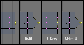
Pressing SHIFT-U re-does the last undo operation (Figure 6.13, “Undo and Redo”).
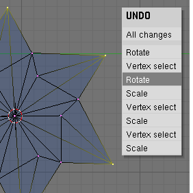
Pressing ALT-U brings up the Undo Menu (Figure 6.14, “Undo Menu”).
This lists all the undo steps by name so you can quickly find your way back to a
known good point in your work. The ALT-U menu also contains the option
All Changes. This option is more powerful than merely
pressing UKEY repeatedly, and will reload the mesh data as it was at the beginning
of your edit session, even if you have used up all your undo steps.
Edit undo can be memory intensive. A mesh of 64,000 faces and verts can use over 3Mb
of RAM per undo step. If you are on a machine that is strapped for RAM,
in the User Preference Window, under Edit Methods, there is
a NumButton for determining the maximum number of undo steps saved.
The allowable range is between 1 and 64. The default is 32.