Configuring and Starting the GlassFish Application Server
When you install full NetBeans 6.0 download, it includes the GlassFish Application Server. NetBeans will automatically start The AppServer when needed.
To start the GlassFish Application Server:
- If the Services window is not visible, choose Window > Services.
- In the Services window, expand the Servers node.
The Servers node should contain a GlassFish Application Server subnode. If a GlassFish Application Server node does not appear, go to To configure the GlassFish Application Server .
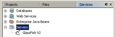
- Right-click the GlassFish Application Server node and select Start.
The Output window displays logging information about the application startup. If the Output window is not visible, choose Window > Output > Output
When the message Application server startup complete. appears in the Output window, the application server is running.
Note: If a green arrow badge appears on the GlassFish Application Server node, the server is running.
Note: Deploying an application to the GlassFish Application Server will automatically start the GlassFish Application Server. Thus, you do not have to manually start the application server.
Note: The following procedures shows how to configure the NetBeans 6.0 IDE to use an alternate version of the GlassFish V2 Application Server.
To configure the GlassFish V2 Application Server:
-
You might want to use a different version of the application server than the one provided with NetBeans 6.0. For example, you might want to download and install a more current version of the GlassFish V2 application server from the GlassFish Community site.
The following procedure shows how to configure the NetBeans 6.0 IDE to use an alternate version of the GlassFish V2 Application Server. It assumes that you have downloaded and installed the alternate version of the application server.
- In the Services window, right-click the Servers node and choose Add Server from the pop-up menu.
The Add Server Instance dialog box opens. - In the Choose Server page, from the list, select GlassFish V2.
- Click Next.
The Platform Folder Location page opens. - In the Platform Location field, use the Browse button to navigate to and select the installation location of the application server.
If you installed the GlassFish application server in the default location, use Table 1 as a guide for locating the installation. Otherwise, navigate to the location where you installed GlassFish V2 Application Server.
Table 1: Default Application Server Installation Directory
Platform Installing As... SOA Installation Tools Bundle Installation Solaris OS
Linuxroot /opt/SUNWappserver /opt/SDK Solaris OS
Linuxuser ~/SUNWappserver ~/SDK Mac OS X N/A ~/SUNWappserver ~/SDK Windows N/A C:\Sun\AppServer C:\Sun\SDK - Select the Register Local Default Domain radio button and click Next.
- Enter the user name and password for the domain's administrator.
If you accepted the default values during the installation, the user name is admin and the password is adminadmin . - Click Finish.
- In the Services window, right-click the Servers node and choose Add Server from the pop-up menu.
Creating the BPEL Module Project
In this section, you create a BPEL Module project called SynchronousSample.
To create the SynchronousSample project:
- From the main menu, choose File > New Project.
The New Project wizard opens. - In the Categories list, select the SOA node, and in the Projects list, select the BPEL Module node.
- Click Next.
- In the Project Name field, type SynchronousSample.
- (Optional) In the Project Location field, use the Browse button to navigate to and select a different folder where the IDE will store the project files.
- Click Finish.
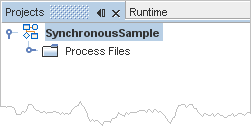
The Projects window now contains a project node for a BPEL Module project called SynchronousSample.
Creating the XML Schema
In this section, you add a new XML schema file to your BPEL Module project and then add XML schema components to the schema.
To create SynchronousSample.xsd:
- In the Projects window, expand the SynchronousSample project node, then right-click the Process Files node and choose New > Other.
The New File wizard opens. - In the New File wizard, do the following:
- In the Choose File Type page, in the Categories list, select the XML node, then in the File Types list, select the XML Schema node and click Next.
- In the File Name field, type SynchronousSample.
- Click Finish.
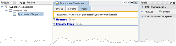
- In the Schema view, click the Design button to open the Design view of the XML schema editor.
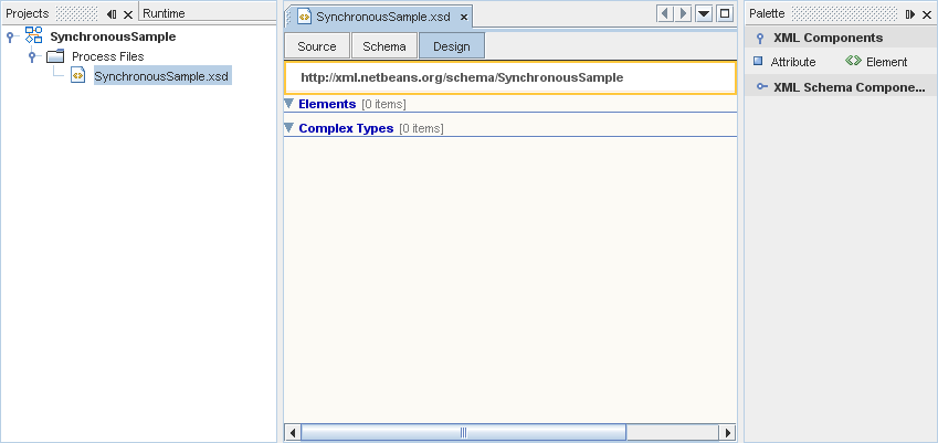
To add a complex type to the XML schema:
- In the Palette of the Design view, expand the XML Schema Components section and select the Complex Type icon.
If the Palette window is not visible, choose Window > Palette from the main menu. - Drag your selection to the schema design area, immediately below the Complex Types node.
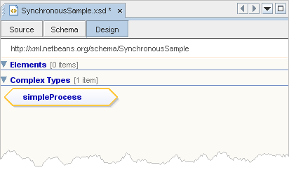
The IDE adds a complex type node and the name of the complex type (newComplexType) is selected and ready for you to change. - Type simpleProcess in the new node and press Enter.
The design area now shows your new complex type, called simpleProcess.
To add a local element to simpleProcess:
- In the XML Components section of the Palette, select the Element icon and drag your selection onto the simpleProcess node in the schema design area.
The IDE adds an element node labeled newElement. - If the Properties window is not visible, choose Window > Properties.
- In the schema design area, select the newElement node.
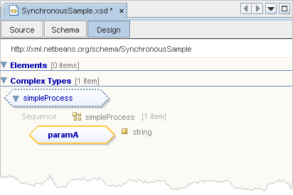
- In the Properties window, select the value field of the Name property to make it editable and type paramA.
- In the Properties window, in the Definition property, click the ellipsis button.
The Definition dialog box opens. - In the list, expand the Built-in Types node and select the string node.
- Click OK.
The IDE updates the Design view.
To add a global element:
- In the XML Components section of the Palette, select the Element icon and drag your selection to the design area, immediately below the Elements node.
The IDE adds anewElementcomponent below the Elements nodes in the schema design area. - In the schema design area of the Design view, select the newElement node.
- In the Properties window, select the value field of the Name property to make it editable and type typeA.
- In the Properties window, in the Definition property, click the ellipsis button.
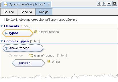
The Element's definition - Definition dialog box opens. - In the list of types, expand the Complex Types node and select the simpleProcess complex type node.
- Click OK.
In the Design view, the IDE now shows the selected simpleProcess complex type next to the typeA element node.
- To save your changes, in the Projects window, select the SynchronousSample project node, and from the main menu, choose File > Save All.
Creating the WSDL Document
In this section, you add a WSDL file to your BPEL Module project and then configure the components of the WSDL Document.
To create SynchronousSample.wsdl:
- In the Projects window, expand the SynchronousSample project node, then right-click the Process Files node and choose New > WSDL Document.
The New WSDL Document wizard opens. - In the Name and Location page, do the following:
- In the File Name field, type SynchronousSample.
- Select the Import XML Schema File(s) checkbox.
- In the XML Schema(s) field, click the Browse button.
The Add Import dialog box opens. This dialog box shows the XML schemas you can import. - Expand By File > SynchronousSample > Process Files, select SynchronousSample.xsd.
Make sure the checkbox in the Import column is selected for the SynchronousSample.xsd row.
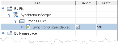
- Click OK.
- Click Next.
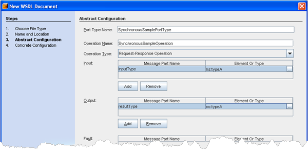
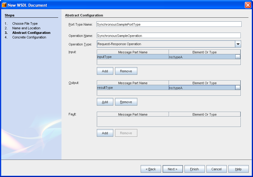
- In the Input area of the Abstract Configuration page, do the following:
- In the Message Part Name column, double-click the default value (part1) to make the field editable.
- Type inputType and press Enter.
- In the Element Or Type column, click the ellipsis button.
The Select Element Or Type dialog box opens. - Expand By File > SynchronousSample > src/SynchronousSample.xsd > Elements.
Note: You may need to scroll up to the top of the list in the Select Element Or Type dialog box to see the By File node. - Under the Elements node, select the typeA node and click OK.
- In the Output area of the Abstract Configuration page, do the following:
- In the Message Part Name column, double-click the default value (part1) to make the field editable.
- Type resultType and press Enter.
- In the Element Or Type column, click the ellipsis button.
The Select Element Or Type dialog box opens. - Expand By File > SynchronousSample > src/SynchronousSample.xsd > Elements.
Note: You may need to scroll up to the top of the list in the Select Element Or Type dialog box to see the By File node. - Under the Elements node, select typeA and click OK.
- Click Next.
The Concrete Configuration page opens. - Under Binding Subtype, select the Document Literal radio button.
- Click Finish.
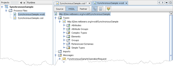
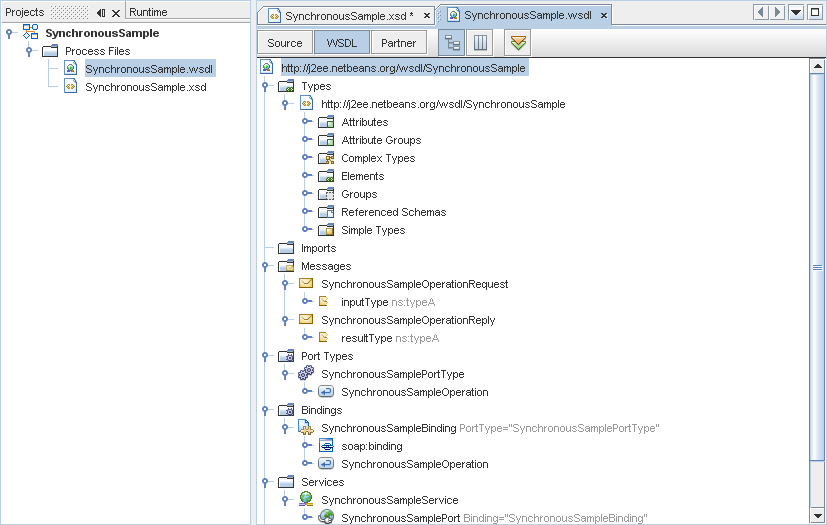
In the Projects window, the Process Files node now contains a subnode labeled SynchronousSample.wsdl.
The Source Editor contains a tab for the WSDL file, SynchronousSample.wsdl, with the WSDL view open.
Creating the BPEL Process
In this section, you create a .bpel file for the BPEL process. You then add a partner link and three activities to the process.
To create SynchronousSample.bpel:
- In the Projects window, right-click the Process Files node and choose New > BPEL Process.
The New BPEL Process wizard opens. - In the File Name field, type SynchronousSample.
- Click Finish.
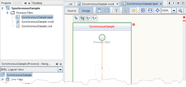
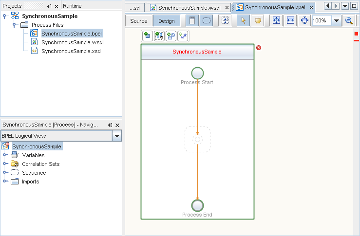
In the Projects window, the Process Files node now contains a subnode labeled SynchronousSample.bpel.
The Source Editor contains a tab for the BPEL process, SynchronousSample.bpel, with the Design view of the BPEL Designer open.
To add a partner link:
- Make sure the Design view for the SynchronousSample.bpel is the active window in the Source Editor.
- In the Projects window, expand the SynchronousSample project node, then expand the Process Files node and select the SynchronousSample.wsdl node.
- Drag your selection (SynchronousSample.wsdl) from the Projects window to the Design view.
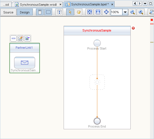
The Create New Partner Link dialog box opens. - Accept the defaults and click OK.
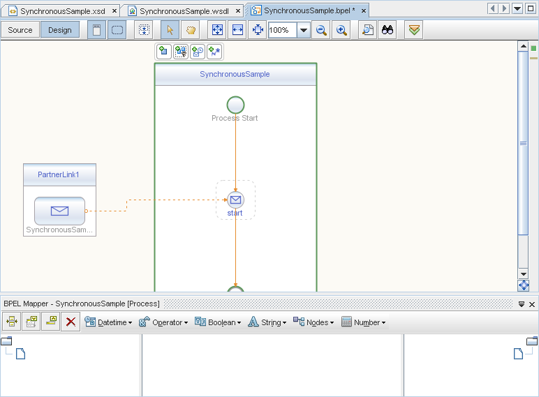
The IDE adds a box for the partner link to the design area.
To add a receive activity:
- Make sure the Design view for the SynchronousSample.bpel is the active window in the Source Editor.
- In the Web Service section of the Palette, select the Receive icon.
- Drag your selection to the SynchronousSample process box in the design area, between the Process Start and the Process End activities.
The IDE provides you with visual clues to show you where you can drop the selection.
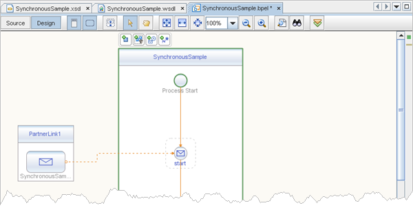
This action places a receive activity called Receive1 in the Design view. - Double-click the Receive1 activity.
The Receive1 [Receive] - Property Editor opens. - On the Main tab, change the value in the Name field to start.
- From the Partner Link drop-down list, select PartnerLink1.
The IDE fills in the Operation field with SynchronousSampleOperation. - Create a new input variable by doing the following:
- Click the Create button next to the Input Variable field.
The New Input Variable dialog box opens. - Change the value in the Name field to inputVar.
- Click OK.
- Click the Create button next to the Input Variable field.
- Click OK to close the Receive1 [Receive] - Property Editor.
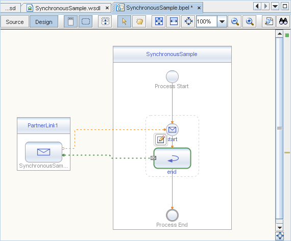
The Design view now shows a connection between PartnerLink1 and the start activity in the SynchronousSample process box.
To add a reply activity:
- Make sure the Design view for the SynchronousSample.bpel is the active window in the Source Editor.
- In the Web Service section of the Palette, select the Reply icon.
- Drag your selection to the design area between the start activity and the Process End activity.
The IDE provides you with visual clues to show you where you can drop the selection.
This action places a reply activity called Reply1 in the Design view. - Double-click the Reply1 activity.
The Reply1 [Reply] - Property Editor opens. - On the Main tab, change the value in the Name field to end.
- From the Partner Link drop-down list, select PartnerLink1.
The IDE fills in the Operation field with SynchronousSampleOperation. - Create a new output variable by doing the following:
- Make sure the Normal Response radio button is selected.
- Click the Create button next to the Output Variable field.
The New Output Variable dialog box opens. - Change the value in the Name field to outputVar.
- Click OK.
- Click OK to close the Reply1 [Reply] - Property Editor.
The Design view now shows a connection between the end activity in the SynchronousSample process box and PartnerLink1.
To add an assign activity:
- Make sure the Design view for the SynchronousSample.bpel is the active window in the Source Editor.
- In the Basic Activities section of the Palette, select the Assign icon.
- Drag your selection to the design area between the start activity and the end activity.
This action places an assign activity called Assign1 in the Design view. - Select the Assign1 activity.
- If the BPEL Mapper window is not visible, choose Window > BPEL Mapper from the main menu.
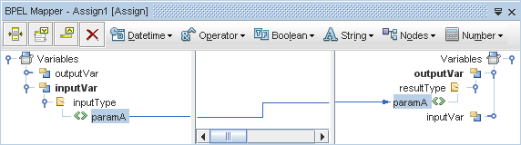
- In the Source tree pane (the left pane) of the BPEL Mapper, under Variables, expand inputVar > inputType.
A paramA node appears under the inputVar node. - In the Destination tree pane (the right pane) of the BPEL Mapper, under Variables, expand outputVar > resultType.
A paramA node appears under the resultType node. - In the Source tree pane, select the paramA node and drag your selection to the paramA node in the Destination pane.
This assignment copies the input statement into the output.
- To save your changes, in the Projects window, select the SynchronousSample project node, and from the main menu, choose File > Save All.
Creating and Deploying the Composite Application
Before you deploy the BPEL Module project, you must add the JBI module to the deployment project. Deploying the project makes the service assembly available to the application server, thus allowing its service units to be run.
To create the Composite Application project and add the JBI module:
- From the main menu, choose File > New Project.
The New Project wizard opens. - In the Categories list, select the SOA node and in the Projects list, select the Composite Application node.
- Click Next.
- In the Project Name field, type SynchronousSampleApplication.
- Click Finish.
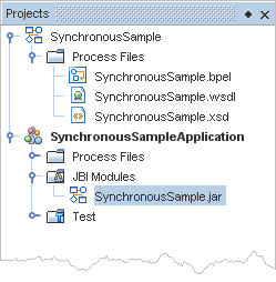
The Projects window now contains a project node for a Composite Application project called SynchronousSampleApplication. - In the Projects window, right-click the SynchronousSampleApplication project node and choose Add JBI Module from the pop-up menu.
The Select Project dialog box opens. - Select the SynchronousSample project you created earlier in this tutorial and click Add Project JAR Files.
The Select Project dialog box closes. - In the Projects window, expand the SynchronousSampleApplication project node and then expand the JBI Modules node.
Notice that a SynchronousSample.jar node has been added.
To deploy the Composite Application:
- Right-click the SynchronousSampleApplication project node and choose Deploy Project.
If a message similar to the following message appears in the Output window, then the deployment has succeeded:
BUILD SUCCESSFUL (total time: 11 seconds)
Testing the Composite Application
You can enhance the Composite Application project by adding test cases, binding to the operation, supplying input, and then using the tester.
To test the SynchronousSampleApplication composite application:
- In the Projects window, expand the SynchronousSampleApplication project node, right-click the Test node, and choose New Test Case from the pop-up menu.
The New Test Case wizard opens. - Accept the default test case name, TestCase1, and click Next.
- In the Select the WSDL Document page, expand the SynchronousSample node, select SynchronousSample.wsdl, and click Next.
- In the Select the Operation to Test page, select the SynchronousSampleOperation and click Finish.
Notice the following:
- In the Projects window, under Test, a new TestCase1 node has been added.
- The TestCase1 node contains two subnodes: Input and Output.
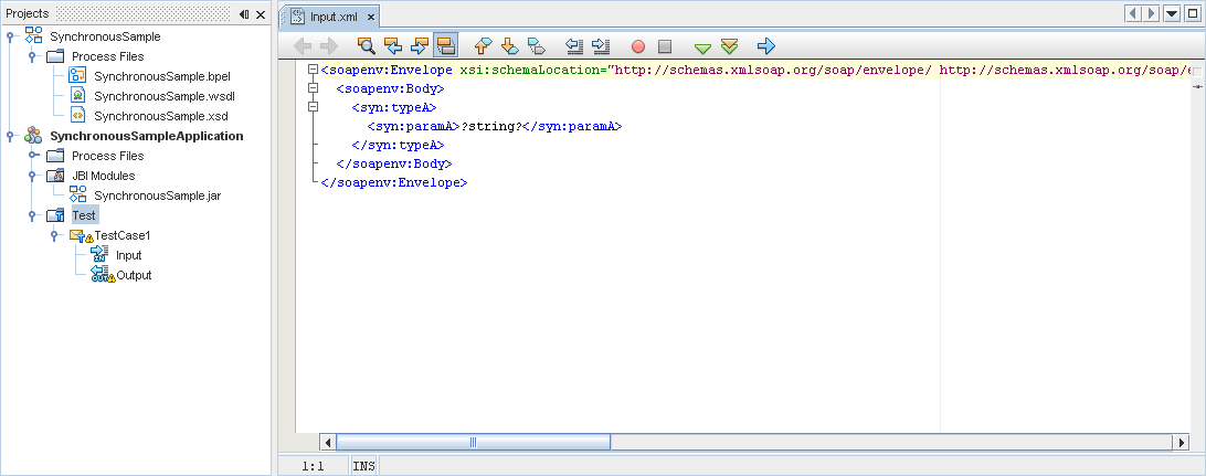
- The Source Editor contains a tab for the Input file, Input.xml.
Note: If the Source Editor does not contain a tab for Input.xml, double-click the Input node in the Projects window to open the file.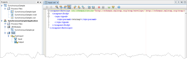
- In the Source Editor tab for the Input.xml file, do the following:
- Locate the following line:
<syn:paramA>?string?<syn:paramA>. - Replace ?string? with Hello World.
The line should look like this:
<syn:paramA>Hello World<syn:paramA>. - From the main menu, choose File > Save All.
- Locate the following line:
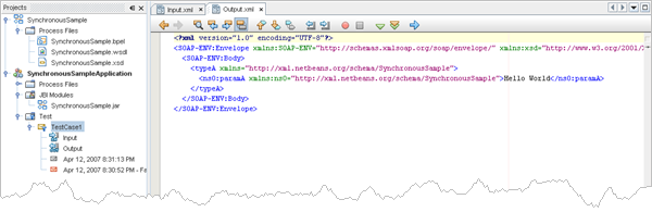
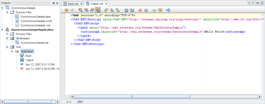
- In the Projects window, double-click the Output node under Test > TestCase1 to examine its contents.
Initially, output.xml is empty. Therefore the first test run will populate output.xml with the real output. Subsequent test runs will compare the real output against the contents of output.xml. - In the Projects window, right-click the TestCase1 node and choose Run from the pop-up menu.
Note: The first run is a special case because Output.xml is empty and the output is written to Output.
Notice the failed message in the Output window.
The Overwrite Empty Output? dialog box opens. - Click Yes.
- In the Projects window, right-click the TestCase1 node and choose Run from the pop-up menu.
After the first run, Output is no longer empty. The file's contents are preserved and are not overwritten by the new result.
Summary
In this tutorial, you created a simple BPEL Module project called SynchronousSample and a Composite Application project called SynchronousSampleApplication. You then designed an XML schema file and a WSDL file. You learned how to design a BPEL process and deploy. You also learned how to create and perform a test run of a composite application.
After completing the steps in this tutorial, you have built the sample Synchronous BPEL Process project that is available in the IDE (New > Project > Samples > SOA > Synchronous BPEL Process).