Creating a Simple SOA Application With NetBeans
Contributed and maintained by Sherry Barkodar, Bob May
October 2007 [Revision number: V1-3]
This publication is applicable to NetBeans IDE/ 6.0 release
In this tutorial, you will create a simple SOA project. You will then add a WSDL document to your project and use the Partner view of the WSDL editor to add the messages, partner link type, port type, and operation. You will then create a composite application project and use the Composite Application (Service Assembly) editor to modify the project configuration. This tutorial also illustrates a basic scenario of how a File Binding Component can be used in a composite application.
Expected duration: 45 minutes
Contents
Tutorial Requirements
Before you proceed, make sure you review the requirements in this section.
Prerequisites
This tutorial assumes that you have some basic knowledge of, or programming experience with, the Java language and platform and the NetBeans IDE.
Software Needed for This Tutorial
Before you begin, you need to install the following software on your computer: NetBeans IDE 6.0 with SOA and the GlassFish application server.
top
Configuring and Starting the GlassFish Application Server
When you install full NetBeans 6.0 download, it includes the GlassFish Application Server. NetBeans will automatically start The Application Server when needed.
To start the GlassFish Application Server:
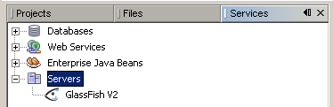
- If the Services window is not visible, choose Window > Services.
- In the Services window, expand the Servers node.
The Servers node should contain a GlassFish Application Server subnode. If a GlassFish Application Server node does not appear, go to To configure the GlassFish Application Server .
- Right-click the GlassFish Application Server node and select Start.
The Output window displays logging information about the application startup. If the Output window is not visible, choose Window > Output > Output
When the message Application server startup complete. appears in the Output window, the application server is running.
Note: If a green arrow badge appears on the GlassFish Application Server node, the server is running.
Note : Deploying an application to the GlassFish Application Server automatically starts the GlassFish Application Server. You do not have to manually start the application server.
Note: The following procedures shows how to configure the NetBeans 6.0 IDE to use an alternate version of the GlassFish V2 Application Server.
To configure the GlassFish V2 Application Server:
-
You might want to use a different version of the application server than the one provided with NetBeans 6.0. For example, you might want to download and install a more current version of the GlassFish V2 application server from the GlassFish Community site.
The following procedure shows how to configure the NetBeans 6.0 IDE to use an alternate version of the GlassFish V2 Application Server. It assumes that you have downloaded and installed the alternate version of the application server.
- In the Services window, right-click the Servers node and choose Add Server from the pop-up menu.
The Add Server Instance dialog box opens.
- In the Choose Server page, from the Server drop-down list, select GlassFish V2.
- Click Next.
The Platform Folder Location page opens.
- In the Platform Location field, use the Browse button to navigate to and select the installation location of the application server.
If you installed the GlassFish application server in the default location, then use Table 1 as a guide for locating the installation. Otherwise, navigate to the location where you installed GlassFish V2 Application Server.
Table 1: Default Application Server Installation Directory
Solaris OS
Linux |
root |
/opt/SUNWappserver |
/opt/SDK |
Solaris OS
Linux |
user |
~/SUNWappserver |
~/SDK |
| Mac OS X |
N/A |
~/SUNWappserver |
~/SDK |
| Windows |
N/A |
C:\Sun\AppServer |
C:\Sun\SDK |
- Select the Register Local Default Domain radio button and click Next.
- Enter the user name and password for the domain's administrator.
If you accepted the default values during the installation, the user name is admin and the password is adminadmin.
- Click Finish.
top
Creating the BPEL Module Project
In this section, you create a BPEL Module project called HelloSample.
To create the project:
- From the main menu, choose File > New Project.
The New Project wizard opens.
- In the Categories list, select the SOA node.
- In the Projects list, select the BPEL Module node.
- Click Next.
- In the Project Name field, type HelloSample.
- (Optional) In the Project Location field, use the Browse button to navigate to and select a different folder where the IDE will store the project files.
- Click Finish.
The Projects window now contains a project node for a BPEL Module project called HelloSample.
top
Creating the WSDL Document
In this section, you add a WSDL document, HelloSample.wsdl to your BPEL Module project and then you use the Partner view of the WSDL editor to configure the components of the WSDL document.
To create the WSDL document:
- In the Projects window, expand the HelloSample project node, right-click the Process Files node and choose New > WSDL Document.
The New WSDL Document wizard opens.
- In the File Name field, type HelloSample.
- Click Finish.
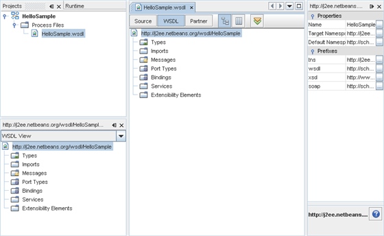
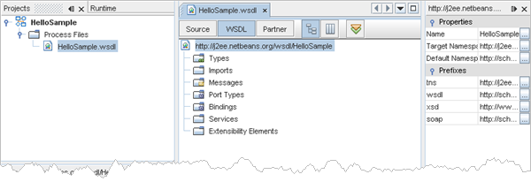
- In the Projects window, the IDE adds a HelloSample.wsdl node under the Process Files node.
- The HelloSample.wsdl file is open in the WSDL editor.
The WSDL editor has three views: Source, WSDL, and Partner.
For more information about the WSDL editor, see Developer Guide to the WSDL Editor.
- The Properties window is open.
If you do not see the Properties window, choose Window > Properties.
- The Navigator window is open.
To add messages:
- In the WSDL view, click the Partner button to open the Partner view of the WSDL editor.
The editor switches to the Partner view and the Palette is opened.
If the Palette window is not visible, choose Window > Palette from the main menu.
- In the WSDL Components section of the Palette, select the Message icon.
- Drag your selection to the Partner view design area, into the Messages area (the lower part of the design area).
The IDE adds a message called message1.
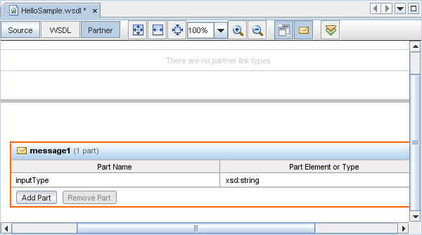
Note: If you do not see the Part Name and Part Element or Type columns, click the down arrow in the message1 box to expand the box.
- In the Part Name column for message1, double-click the default value, part1 to make the field editable.
- Type inputType and press Enter.
- In the Part Element or Type column for message1, click the ellipsis button, and in the dialog box that opens, expand Built-In Schema Types, select string and click OK.
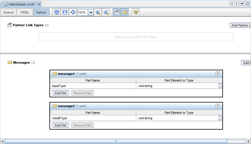
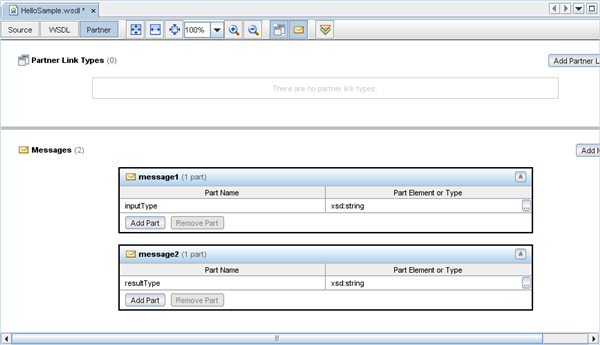
- Repeat steps 2-6 to create another message, message2 and use resultType as the Part Name.
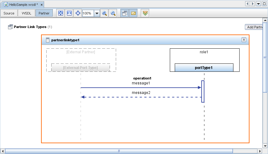
When you are done, your design area should look similar to the one shown below.
To add a partner link type:
- In the WSDL Components section of the Palette, select the Partner Link Type icon.
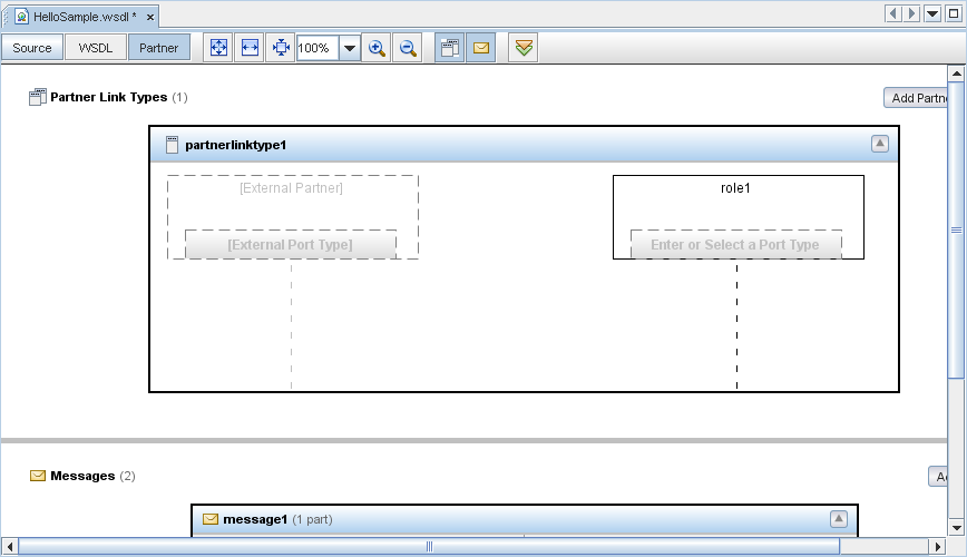
- Drag your selection to the design area, into the Partner Link Types area (the upper part of the design area).
The IDE adds a partner link type called partnerlinktype1. You can now create new roles and port types. Roles and port types are drawn as dotted vertical lines with the external names shown at the top.
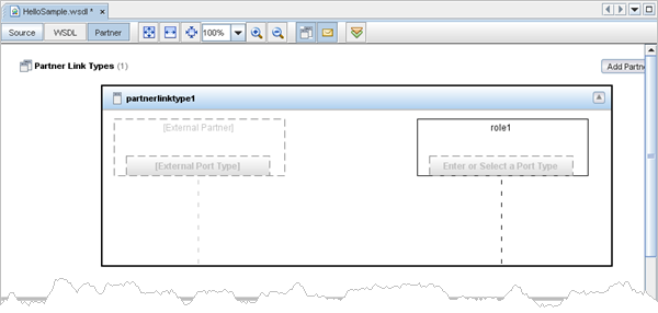
- In the partnerlinktype1 box, double-click the box under role1.
This makes the port type editable and a default value portType1, appears in the field.
- Press Enter.
The new portType1 is assigned.
- In the WSDL Components section of the Palette, select the Request-Response icon.
- Drag your selection to the design area, below portType1.
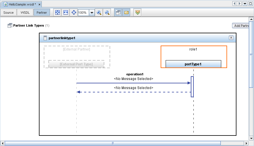
The IDE adds an operation, operation1.
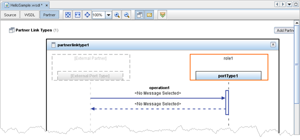
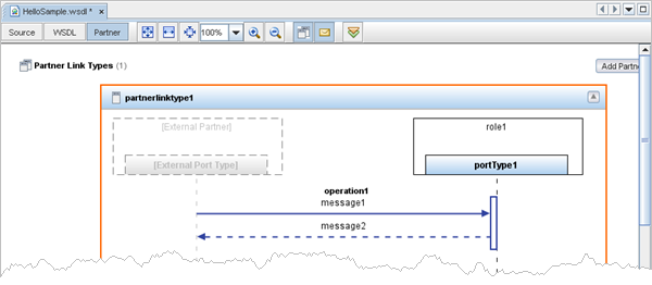
- Under operation1, select the solid message arrow labeled <No Message Selected>.
- In the Properties window, from the Message drop-down list, select tns:message1.
The label changes to message1.
- Under operation1, select the dotted message arrow labeled <No Message Selected>.
- In the Properties window, from the Message drop-down list, select tns:message2.
The label changes to message2.
When you have completed these steps, your design area should look similar to the one shown below.
top
Creating the BPEL Process
In this section, you add a BPEL process file, HelloSample.bpel. You then add a partner link and three activities to the BPEL process file.
To create the BPEL process file:
- In the Projects window, expand the HelloSample project node, right-click the Process Files node and choose New > BPEL Process.
The New BPEL Process wizard opens.
- In the File Name field, type HelloSample.
- Click Finish.
- In the Projects window, the IDE adds a HelloSample.bpel node under the Process Files node.
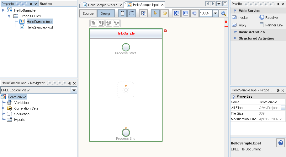
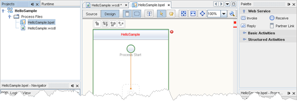
- The HelloSample.bpel file is open in the BPEL Designer.
The BPEL Designer has two views: Source and Design.
For more information about the BPEL Designer, see Developer Guide to the BPEL Designer.
- The Properties window is open.
If you do not see the Properties window, choose Window > Properties.
- The Navigator window is open showing the BPEL Logical View of the BPEL Process document.
The IDE window should look similar to the one shown below.
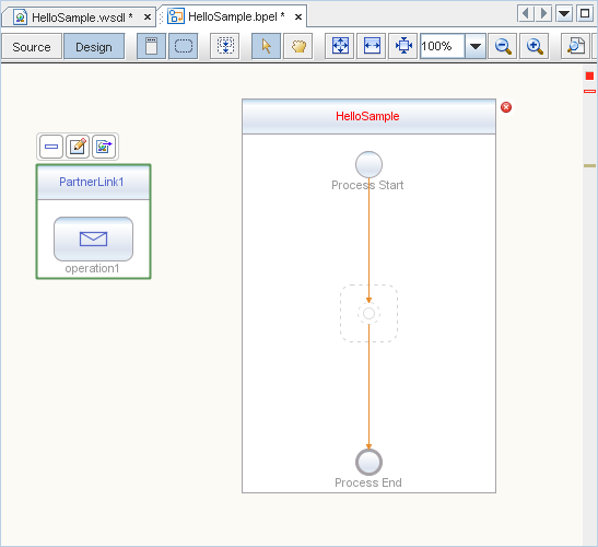
To add a partner link:
- In the Web Service section of the Palette, select the Partner Link icon and drag your selection to the design area.
The Create New Partner Link dialog box opens.
- Accept the defaults (Name: PartnerLink1, WSDL File: /HelloSample.wsdl, Use Existing Partner Link Type radio button selected) and click OK.
The IDE adds the partner link to the design area.
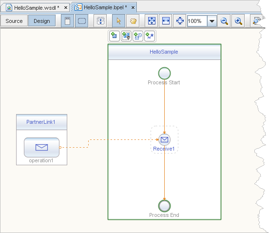
To add a receive activity:
- In the Web Service section of the Palette, select the Receive icon.
- Drag your selection to the HelloSample box in the design area, between the Process Start and the Process End activities.
The IDE provides you with visual clues to show you where you can drop the selection.
This action places a receive activity called Receive1 in the Design view.
- Double-click the Receive1 activity.
The Receive1 [Receive] - Property Editor opens.
- On the Main tab, from the Partner Link drop-down list, select PartnerLink1.
The IDE fills in the Operation field with operation1.
- Create a new input variable by doing the following:
- Click the Create button next to the Input Variable field.
The New Input Variable dialog box opens.
- Change the value in the Name field to inputVar.
- Click OK.
- Click OK to close the Receive1 [Receive] - Property Editor.
The Design view now shows a connection between operation1 in PartnerLink1 and the Receive1 activity.
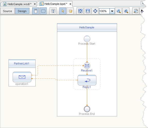
To add a reply activity:
- In the Web Service section of the Palette, select the Reply icon.
- Drag your selection to the design area between the Receive1 activity and the Process End activity.
The IDE provides you with visual clues to show you where you can drop the selection.
This action places a reply activity called Reply1 in the Design view.
- Double-click the Reply1 activity.
The Reply1 [Reply] - Property Editor opens.
- On the Main tab, from the Partner Link drop-down list, select PartnerLink1.
The IDE fills in the Operation field with operation1.
- Create a new output variable by doing the following:
- Make sure the Normal Response radio button is selected.
- Click the Create button next to the Output Variable field.
The New Output Variable dialog box opens.
- Change the value in the Name field to outputVar.
- Click OK.
- Click OK to close the Reply1 [Reply] - Property Editor.
The Design view now shows a connection between the Reply1 activity and operation1 in PartnerLink1.
To add an assign activity:
- In the Basic Activities section of the Palette, select the Assign icon.
- Drag your selection to the design area between the Receive1 activity and the Reply1 activity.
This action places an assign activity called Assign1 in the Design view.
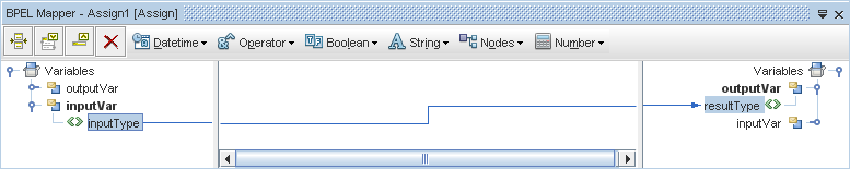
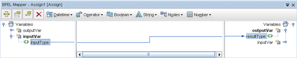
- Select the Assign1 activity.
- If the BPEL Mapper window is not visible, choose Window > Other > BPEL Mapper from the main menu.
- In the Source tree pane (the left pane) of the BPEL Mapper, under Variables, expand the inputVar node.
An inputType node appears under the inputVar node.
- In the Destination tree pane (the right pane) of the BPEL Mapper, under Variables, expand the outputVar node.
A resultType node appears under the outputVar node.
- In the Source tree pane, select the inputType node and drag your selection to the resultType node in the Destination tree pane.
This assignment copies the input statement into the output.
- To save your changes, in the Projects window, select the HelloSample project node, and from the main menu, choose File > Save All.
top
Creating the Composite Application Project
Before you deploy the BPEL Module project, you must add the JBI module to the deployment project. Deploying the project makes the service assembly available to the application server, thus allowing its service units to be run.
To create the Composite Application project:
- From the main menu, choose File > New Project.
The New Project wizard opens.
- In the Categories list, select the SOA node.
- In the Projects list, select the Composite Application node.
- Click Next.
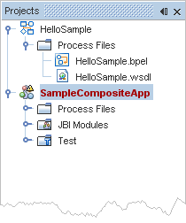
- In the Project Name field, type SampleCompositeApp.
- Click Finish.
The Projects window now contains a project node for a Composite Application project called SampleCompositeApp.
top
Using the Composite Application (Service Assembly) Editor
In this section, you use the Composite Application (Service Assembly) editor to modify the project configuration and build the BPEL Module project. You then add a WSDL endpoint and a connection and then you verify and change the properties of the auto-generated WSDL endpoints.
To use the Composite Application (Service Assembly) editor to modify the project configuration and build the BPEL Module project:
- In the Projects window, select the SampleCompositeApp project node and choose Edit Application Configuration from the pop-up menu.
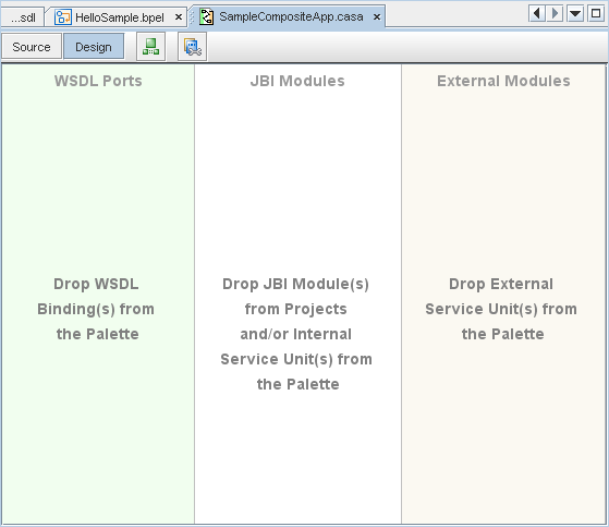
The IDE opens the .casa file in the Composite Application (Service Assembly) editor. The design area of the Design view of the editor has three parts: WSDL Ports, JBI Modules, and External Modules.
- In the Projects window, select the HelloSample project node and drag your selection to the JBI Modules area in the Design view of the SampleCompositeApp.casa file.
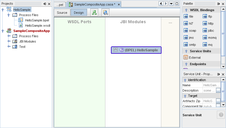
- In the editor toolbar, click the Build Project button to build the HelloSample BPEL Module project.
When this step has completed:
- The status bar message shows the following message:
Finished building build.xml (jbi-build).
- The Output window should look similar to the one shown below.

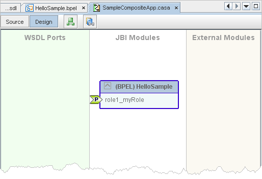
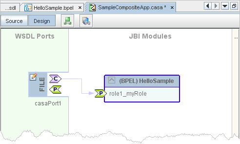
- The Design view of the SampleCompositeApp.casa file should look similar to the one shown below.
To create the WSDL endpoint:
- In the WSDL Bindings section of the Palette, select the file icon.
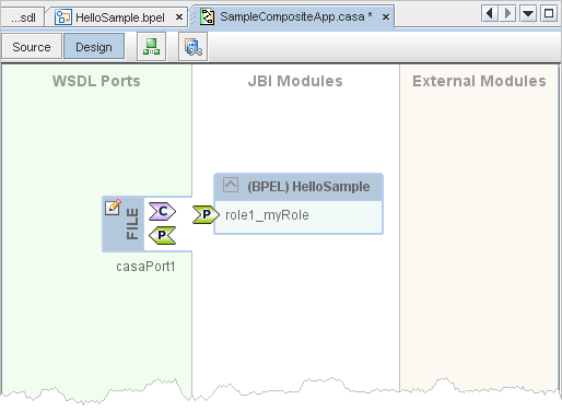
- Drag your selection to the WSDL Ports area in the Design view of the SampleCompositeApp.casa file.
The IDE adds a WSDL port labeled casaPort1.
To create a connection:
- In the casaPort1 port in the Design view, click the consume endpoint icon, .
The colors of the icon change when you select the endpoint: .
- Drag your selection to role1_myRole in the (BPEL) HelloSample box in the JBI Modules area.
The IDE creates a new connection.
To verify and change the properties of the auto-generated WSDL endpoint:
- If the Navigator window is not visible, choose Window > Navigating > Navigator from the main menu.
- In the Navigator window, from the drop-down list, select Logical View.
- Expand WSDL Ports > casaPort1 > casaBinding1 > operation1 > input1 and select the file:message node.
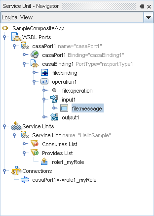
- If the Properties window is not visible, choose Window > Properties from the main menu.
The Properties window shows the properties of the file:message node you selected in the Navigator window.
- In the Properties window, change the properties to match the values shown below:
| use |
literal |
| fileName |
input.txt |
| pollingInterval |
5000 |
- In the Navigator window, expand WSDL Ports > casaPort1 > casaBinding1 > operation1 > output1 and select the file:message node.
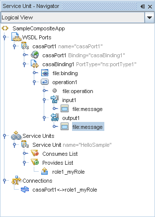
- In the Properties window for file:message, assign output.txt to the fileName property.
- In the Navigator window, expand WSDL Ports > casaPort1 > casaPort1 and select the file:address node.
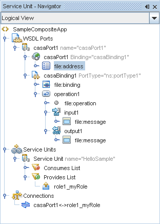
- In the Properties window for file:address, in the fileDirectory property, replace C:\Temp with the string c:\test.
- To save your changes, in the Projects window, select the SampleCompositeApp project node, and from the main menu, choose File > Save All.
top
Deploying and Testing the Composite Application
In this section, you deploy the Composite Application project and then test that deployed application. If you skipped the steps in Configuring and Starting the Sun Java System Application Server earlier in this tutorial, you must perform them before these deployment and test tasks.
To deploy the Composite Application:
- In the Projects window, select the SampleCompositeApp project node, right-click and choose Deploy.
A message similar to the following message appears in the Output window:
BUILD SUCCESSFUL (total time: 6 seconds)
To test the Composite Application:
- Use an editor to create a new text file that contains the string Hello World! and save the file as input.txt in the c:\test folder.
The running process should do the following:
- Create input.txt<UUID> _processed under the archive folder.
- Create output.txt in the C:/test folder with the same content as input.txt, in this case, the string Hello World!.
If this does not happen then there is an error processing which will do the following:
- Create input.txt<UUID> _error under the c:\test\filebc_tmp folder
top
Summary
In this tutorial, you created a BPEL Module project. You then added a WSDL document to your project and used the Partner view of the WSDL editor to add the messages, partner link type, port type, and operation. Next, you created a composite application project and used the Composite Application (Service Assembly) editor to modify the project configuration. You also used the File Binding Component in the composite application.
top
Next Steps
To send comments and suggestions, obtain support, and stay informed of the latest
changes to the NetBeans IDE J2EE development features, join the [email protected]
mailing list.
See Also
top