Chapter 8
Directory Design Examples
How you design your directory depends upon the size and nature of your enterprise. This chapter provides examples of how a directory can be applied within a variety of different settings. You can use these examples as a starting point for developing your own directory deployment plan.
This chapter contains the following example directory designs:
An Enterprise
example.com Corporation, an automobile parts manufacturer, is a small company that consists of 500 employees. example.com decides to deploy Red Hat Directory Server (Directory Server) to support the directory-enabled applications it uses. example.com's directory design process involves the following steps:
- Data Design
- Schema Design
- Directory Tree Design
- Topology Design
- Replication Design
- Security Design
- Tuning and Optimizations
- Operations Decisions
Data Design
example.com first decides the type of data it will store in the directory. To do this, example.com creates a deployment team that performs a site survey to determine how the directory will be used. The deployment team determines the following:
- example.com's directory will be used by a messaging, web server, a calendar server, a human resources application, and a white pages application.
- The messaging server does exact searches on attributes such as the uid, mailServerName, and mailAddress attributes. To improve database performance, example.com will maintain indexes for these attributes to support searches by the messaging server.
- For more information on using indexes, see "Using Indexes to Improve Database Performance," on page 106.
- The white pages application will frequently search for user names and phone numbers. The directory will therefore need to be able to handle lots of substring, wildcard, and sounds-like searches which return large sets of results. example.com decides to maintain approximate and substring indexes for the dn, sn, and givenName attributes.
- example.com's directory maintains user and group information to support an LDAP server-based intranet deployed throughout the organization. Most of example.com's user and group information will be centrally managed by a group of directory administrators. However, example.com also wants email information to be managed by a separate group of mail administrators.
- example.com plans to support public key infrastructure (PKI) applications in the future, such as S/MIME email, so it needs to be prepared to store the public key certificates of users in the directory.
Schema Design
example.com's deployment team decides to use the inetOrgPerson object class to represent the entries in the directory. This object class is appealing because it allows the userCertificate and uid(userID) attributes, both of which are needed by the applications supported by example.com's directory.
example.com also wants to customize the default directory schema. example.com creates the examplePerson object class to represent employees of example.com Corporation. It derives this object class from the inetOrgPerson object class.
The examplePerson object class allows one attribute, the exampleID attribute. This attribute contains the special employee number assigned to each example.com employee.
In the future, example.com can add new attributes to the examplePerson object class as needed.
Directory Tree Design
example.com creates a directory tree as follows:
- The root of the directory tree is example.com's Internet domain name: dc=example,dc=com.
- The directory tree has four branch points: ou=people, ou=groups, ou=roles, and ou=resources.
- All of example.com's people entries are created under the ou=people branch.
- The people entries are all members of the person, organizationalPerson, inetOrgPerson, and examplePerson object classes. The uid attribute uniquely identifies each entry's DN. For example, example.com contains entries for Babs Jensen (uid=bjensen) and Emily Stanton (uid=estanton).
- example.com creates three roles, one for each department in example.com: sales, marketing, and accounting.
- Each person entry contains a role attribute which identifies the department to which the person belongs. example.com can now create ACIs based upon these roles.
- For more information about roles, refer to "About Roles," on page 73.
- The first group, cn=administrators, contains entries for the directory administrators that manage the directory contents.
- Mail administrators use the second group, cn=messaging admin, to manage mail accounts. This group corresponds to the administrators group used by the messaging server. example.com makes sure that the group it configures for the messaging server is different from the group it creates for Directory Server.
- Two branches are created under the ou=resources branch, one for conference rooms (ou=conference rooms) and one for offices (ou=offices).
- example.com creates a class of service (CoS) that provides values for the mailquota attribute depending upon whether an entry belongs to the administrative group.
- This CoS gives administrators a mail quota of 500 MB while ordinary example.com employees have a mail quota of 100 MB.
- For more information about CoS, refer to "About Class of Service," on page 75.
The following diagram illustrates the directory tree resulting from the design steps listed above:
Figure 8-1 Directory Tree for example.com Corporation

|
Topology Design
Next, example.com designs both its database and server topologies. The following sections describe each topology in detail.
Database Topology
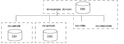
example.com designs a database topology in which the people branch is stored in one database (DB1), the groups branch is stored in another database (DB2), and the resources branch, roles branch, and the root suffix information are stored in a third database (DB3). The database topology for example.com's directory looks as follows:
Figure 8-2 Database Topology for example.com Corporation
|
Server Topology
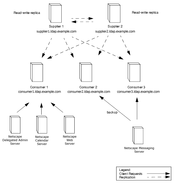
Each of the two supplier servers updates all three consumer servers in example.com's deployment of Directory Server. These consumers supply data to one messaging server and to the other Unified User Management products.
The example.com server topology follows:
Figure 8-3 Server Topology for example.com Corporation
|
Modify requests from compatible servers are routed to the appropriate consumer server. The consumer server uses smart referrals to route the request to the supplier server responsible for the master copy of the piece of data being modified.
Replication Design
example.com decides to use a multi-master replication design to ensure the high availability of its directory data. For more information about multi-master replication, refer to "Multi-Master Replication," on page 115.
The following sections provide more details about the supplier server architecture and the supplier-consumer server topology.
Supplier Architecture
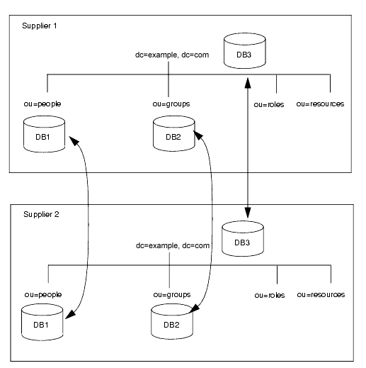
example.com uses two supplier servers in a multi-master replication architecture. The suppliers update one another so that the directory data remains consistent. The supplier architecture works as follows:
Figure 8-4 Supplier Architecture for example.com Corporation
|
Supplier Consumer Architecture
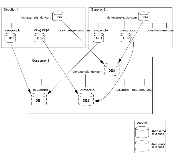
The following diagram describes how the supplier servers replicate to each consumer in the example.com deployment of the directory:
Figure 8-5 Supplier/Consumer Architecture for example.com Corporation
|
Each of the three consumer servers is updated by the two supplier servers as shown in Figure 8-5. This ensures that the consumers will not be affected if there is a failure in one of the supplier servers.
Security Design
example.com decides on the following security design to protect its directory data:
- example.com creates an ACI that allows employees to modify their own entries.
- Users can modify all attributes except the uid, manager and department attributes.
- To protect the privacy of employee data, example.com develops an ACI that allows only the employee and an employee's manager to see the employee's home address and phone number.
- example.com creates at the root of the directory tree an ACI that allows the two administrator groups the appropriate directory permissions.
- The directory administrators group needs full access to the directory. The messaging administrators group needs write and delete access to the mailRecipient and mailGroup object classes and the attributes contained on those object classes, as well as the mail attribute. example.com also grants the messaging administrators group write, delete, and add permissions to the group subdirectory for creation of mail groups.
- A general access control is created on the root of the directory tree that allows anonymous access for read, search, and compare access.
- This ACI denies anonymous users access to password information.
- To protect the server from denial of service attacks and inappropriate use, example.com sets resource limits based on the DN used by directory clients to bind.
- example.com allows anonymous users to receive 100 entries at a time in response to search requests, administrative users to receive 1,000 entries, and system administrators to receive an unlimited number of entries. For more information about setting resource limits based on the bind DN, refer to chapter 7, "User Account Management," in the Red Hat Directory Server Administrator's Guide.
- example.com creates a password policy where passwords must be at least 8 characters in length and expire after 90 days.
- For more information about password policies, refer to "Designing a Password Policy," on page 147.
- example.com creates an ACI that gives members of the accounting role access to all payroll information.
Tuning and Optimizations
example.com optimizes its deployment of directory by doing the following:
- The dsktune utility provides an easy and reliable way of checking the patch levels and kernel parameter settings for your system. For more information about dsktune, see the Red Hat Directory Server Installation Guide.
- example.com sets the entry cache to 2000 entries and the database cache to 250 MB to ensure that all of the indexes fit into RAM, optimizing server performance.
Operations Decisions
example.com makes the following decisions regarding the day-to-day operation of its directory:
- Back up the databases every night, and write the backups to tape once a week.
- Use SNMP to monitor the server status.
- For more information about SNMP, refer to the Red Hat Directory Server Administrator's Guide.
- Auto-rotate the access logs.
- Monitor the error log to see if the server is performing as expected.
- Monitor the access log to screen for searches that should be indexed.
- For more information about the access, error, and audit logs, refer to chapter 12, "Monitoring Server and Database Activity," in the Red Hat Directory Server Administrator's Guide.
A Multinational Enterprise and Its Extranet
This example builds a directory infrastructure for example.com International. example.com Corporation from the previous example has grown into a large, multinational company. This example builds on the directory structure created in the last example for example.com Corporation, expanding the directory design to meet its new needs.
example.com has grown into an organization dispersed over three main geographic locations: the US, Europe, and Asia. example.com now has more than 20,000 employees, all of which live and work in the countries where the example.com offices are located. example.com decides to launch a company-wide LDAP directory to improve internal communication, to make it easier to develop and deploy web applications, and to increase security and privacy.
Designing a directory tree for an international corporation involves determining how to collect directory entries logically, how to support data management, and how to support replication on a global scale.
In addition, example.com wants to create an extranet for use by its parts suppliers and trading partners. An extranet is an extension of an enterprise's intranet to external clients.
The following sections describe the steps in the process of deploying a multinational directory service and extranet for example.com International:
Data Design
example.com International creates a deployment team to perform a site survey. The deployment team determines the following from the site survey:
- A messaging server is used to provide electronic mail routing, delivery, and reading services for most of example.com's sites. An enterprise server is used to provide document publishing services. All servers run on the Solaris UNIX operating system.
- example.com needs to allow data to be managed locally. For example, the European site will be responsible for managing the Europe branch of the directory. This also means that Europe will be responsible for the master copy of its data.
- Because of the geographic distribution of example.com's offices, the directory needs to be available to users and applications 24 hours a day.
- Many of the data elements need to accommodate data values of several different languages and charactersets.
The deployment team also determines the following about the data design of the extranet:
- Suppliers will need to log in to example.com's directory to manage their contracts with example.com. Suppliers will depend upon data elements used for authentication, such as name and user password.
- example.com's partners will use the directory as a way to look up the email addresses and phone number of people in the partner network.
Schema Design
example.com builds upon its original schema design by adding schema elements to support the extranet. example.com adds two new objects, the exampleSupplier object class and the examplePartner object class.
The exampleSupplier object class allows one attribute, the exampleSupplierID attribute. This attribute contains the unique ID assigned by example.com International to each auto parts supplier with which it works.
The examplePartner object class allows one attribute, the examplePartnerID attribute. This attribute contains the unique ID assigned by example.com International to each trade partner.
For information about customizing the default directory schema, refer to "Customizing the Schema," on page 48.
Directory Tree Design
example.com creates a directory tree as follows:
- The directory tree is rooted in the suffix dc=com. Under this suffix, example.com creates two branches. One branch, dc=exampleCorp,dc=com, contains data internal to example.com International. The other branch, dc=exampleNet,dc=com, contains data for the extranet.
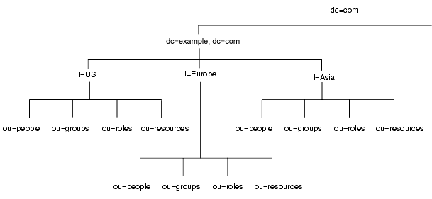
- The directory tree for the intranet (under dc=exampleCorp,dc=com) has three main branches, each corresponding to one of the regions where example.com has offices. These branches are identified using the l(locality) attribute.
- Each main branch under dc=exampleCorp,dc=com mimics the original directory tree design of example.com Corporation. Under each locality, example.com creates an ou=people, an ou=groups, an ou=roles, and an ou=resources branch. See Figure 8-1, on page 174, for more information about this directory tree design.
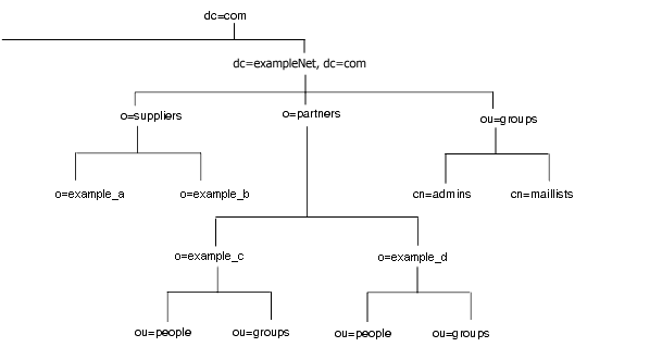
- Under the dc=exampleNet,dc=com branch, example.com creates three branches. One branch for suppliers (o=suppliers), one branch for partners (o=partners), and one branch for groups (ou=groups).
- The ou=groups branch of the extranet contains entries for the administrators of the extranet as well as mailing lists that partners subscribe to for up-to-date information on auto part manufacturing.
The basic directory tree that results appears as follows:
Figure 8-6 Basic Directory Tree for example.com International

|
The directory tree for the example.com intranet appears as follows:
Figure 8-7 Directory Tree for example.com International's Intranet
|
The entry for the l=Asia entry appears in LDIF as follows:
dn: l=Asia,dc=exampleCorp,dc=com

objectclass: top

objectclass: locality

l: Asia

description: includes all sites in Asia
The directory tree for example.com's extranet appears as follows:
Figure 8-8 Directory Tree for example.com International's Extranet
|
Topology Design
Next, example.com designs both its database and server topologies. The following sections describe each topology in more detail.
Database Topology
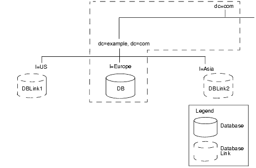
The following diagram illustrates the database topology of one of example.com's main localities, Europe:
Figure 8-9 Database Topology for example.com Europe
|
The database links point to databases stored locally in each country. For example, operation requests received by the example.com Europe server for the data under the l=US branch are chained by a database link to a database on a server in Austin, Texas. For more information about database links and chaining, refer to "Using Chaining," on page 100.
The master copy of the data for dc=exampleCorp,dc=com and the root entry, dc=com, is kept in the l=Europe database, as shown by the box in Figure 8-9.
The data center in Europe contains the master copies of the data for the extranet. The extranet data is stored in three databases, one for each of the main branches. The following figure shows the database topology for the extranet.
Figure 8-10 Database Topology for example.com International's Extranet

|
As illustrated in Figure 8-10, the master copy of the data for o=suppliers is stored in database one, the master copy of the data for o=partners is stored in database two, and the master copy of the data for ou=groups is stored in database three.
Server Topology
example.com develops two server topologies, one for the corporate intranet and one for the partner extranet.
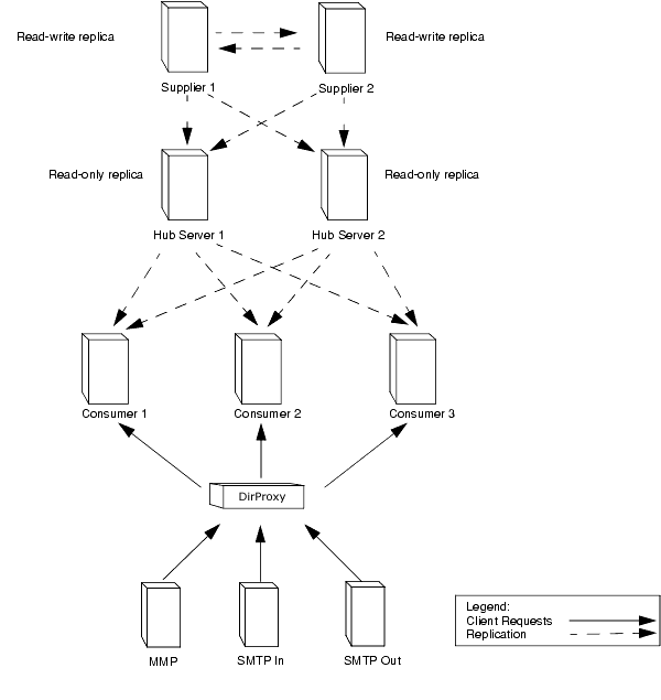
For the intranet, example.com decides to have a master database for each major locality. This means it has three data centers, each containing two supplier servers, two hub servers, and three consumer servers.
The architecture of example.com Europe's data center appears as follows:
Figure 8-11 Server Topology for example.com Europe
|
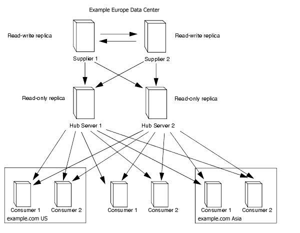
example.com's extranet data is mastered in Europe. This data is replicated to two consumer servers in the US data center and two consumer servers in the Asia data center. In all, example.com requires ten servers to support the extranet.
The server architecture of example.com's extranet appears as follows in the example.com Europe data center:
Figure 8-12 Server Topology for example.com International's Extranet
|
The hub servers replicate the data to two consumer servers in the example.com Europe data center, two consumer servers in the example.com US data center, and two consumer servers in the example.com Asia data center.
Replication Design
example.com considers the following when designing replication for its directory:
- Data will be managed locally.
- Quality of network connections varies from site to site.
- Database links will be used to connect data on remote servers.
- Hub servers that contain read-only copies of the data will be used to replicate data to consumer servers.
- The hub servers are located near important directory-enable applications such as a mail server or a web server.
- Hub servers remove the burden of replication from the supplier servers, so the suppliers can concentrate on doing write operations. In the future, as example.com expands and needs to add more consumer servers, the additional consumers do not affect the performance of the suppliers.
- For more information about hub servers, refer to "Cascading Replication," on page 119.
- Hub servers remove the burden of replication from the supplier servers, so the suppliers can concentrate on doing write operations. In the future, as example.com expands and needs to add more consumer servers, the additional consumers do not affect the performance of the suppliers.
Supplier Architecture
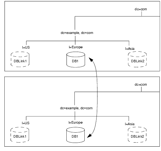
For the example.com intranet, each locality keeps the master copy of its data and uses database links to chain to the data of other localities. For the master copy of its data, each locality uses a multi-master replication architecture. For example, the supplier architecture for Europe, which includes the dc=exampleCorp,dc=com and dc=com information, appears as follows:
Figure 8-13 Supplier Architecture for example.com Europe
|
Each locality contains two suppliers, which share master copies of the data for that site. Each locality is therefore responsible for the master copy of its own data. Using a multi-master architecture ensures the availability of the data and helps balance the workload managed by each supplier server.
To reduce the risk of total failure, example.com Corporation uses multiple read-write supplier Directory Servers at each site.
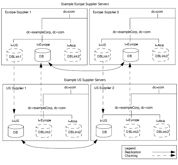
The following diagram illustrates the interaction between the two supplier servers in Europe and the two supplier servers in the US:
Figure 8-14 Supplier/Supplier Architecture for example.com Europe and example.com US
|
The same relationship as illustrated in Figure 8-14 exists between example.com US and example.com Asia, and between example.com Europe and example.com Asia.
Security Design
example.com International builds upon its previous security design, adding the following access controls to support its new multinational intranet:
- example.com adds general ACIs to the root of the intranet, creating more restrictive ACIs in each country and the branches beneath each country.
- example.com decides to use macro ACIs to minimize the number of ACIs in the directory.
- example.com uses a macro to represent a DN in the target or bind rule portion of the ACI. When the directory gets an incoming LDAP operation, the ACI macros are matched against the resource targeted by the LDAP operation. If there is a match, the macro is replaced by the value of the DN of the targeted resource.
- For more information about macro ACIs, refer to the Red Hat Directory Server Administrator's Guide.
example.com adds the following access controls to support its extranet:
- example.com decides to use certificate-based authentication for all extranet activities. When people log in to the extranet, they need a digital certificate. The directory is used to store the certificates. Because the directory stores the certificates, users can send encrypted email by looking up public keys stored in the directory.
- example.com creates an ACI that forbids anonymous access to the extranet. This protects the extranet from denial of service attacks.
- example.com wants updates to the directory data to come only from an example.com hosted application. This means that partners and suppliers using the extranet can only use the tools provided by example.com. Restricting extranet users to example.com's preferred tools allows example.com administrators to use the audit logs to track the use of the directory and limits the types of problems that can be introduced by extranet users outside of example.com International.