These are actions concerned with input and output and the overall management of projects and the ArgoUML system.
Shortcut Ctrl-N.
This initializes a new project within ArgoUML. The
project is created without a the name. It contains a
(top-level) Model named
untitledModel and two empty diagrams: a class
diagram and a use case diagram.
![[Caution]](images/caution.png) | Caution |
|---|---|
|
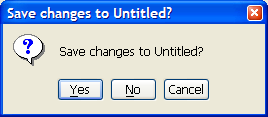
If the model has been altered (as indicated by the "*" in the titlebar of ArgoUML's window), then activating the "New" function is potentionally not the user's intention, since it will erase the changes. Hence a confirmation dialog appears to allow the user to save his work first, or cancel the operation completely.

Shortcut Ctrl-O.
This opens an existing project from a file. Selecting
this menu option will open a file selection dialog (see
Figure 10.2, “
The file selection dialog for
Open Project....
”).
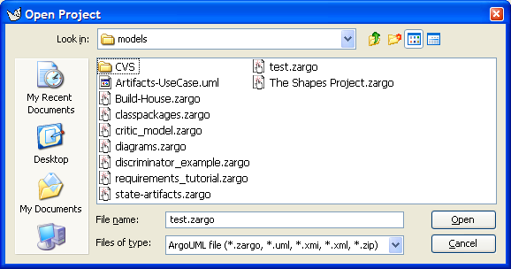
The main body of the dialog is a text area with a listing of all directories and files in the currently selected directory which match the current filter (see below).
Navigating in the directory tree is possible by selecting a directory in the drop down selector at the top of this dialog. Navigating deeper in the tree may be done by double clicking button 1 on the directory shown in the main text area.
In the lower portion of the dialog is a text box
labeled File name: for the name of the
file to be opened. The file name may be typed directly in
here, or selected from the directory listing above using
button 1 click.
Beneath this is a drop down selector labeled
Files of type: to specify a filter on the files to
be shown in the directory listing. Only files that match the
filter are listed. The available filters are listed below.
The default filter is the first one,
which combines all available formats.
ArgoUML file (*.zargo, *.uml, *.xmi, *.xml, *.zip)
ArgoUML compressed project file (*.zargo)
ArgoUML project file (*.uml)
XML Metadata Interchange (*.xmi)
XML Metadata Interchange (*.xml)
XMI compressed project file (*.zip)
Shortcut Ctrl-S.
This saves the project using its current file name. Use
Save Project As... to save the project to a
different file. If no filename is given yet (e.g. after
New), then this function works exactly as
Save Project As....
![[Note]](images/note.png) | Note |
|---|---|
In certain circumstances, there is nothing to save, and this menuitem is downlighted. E.g. when the user did not yet alter a loaded project. The presence of a “*” in the titlebar of ArgoUML's window indicates that the current project is “dirty” (has been altered), and can be saved. |
This opens a dialog allowing you to save the project under a different file name (or to specify a file name for the first time if the project is a new project).
The dialog box is almost identical to that for
Open Project (see
Figure 10.2, “
The file selection dialog for
Open Project....
”). The extension
of the filename is automatically set.
This menu-item allows you to throw away all your recent
changes, and reload the last saved version of the current
project. It works a bit like an Undo
feature, but only restores changes done since the last time
the file was saved.
This menu-item is downlighted unless the currentproject has been saved or loaded before (i.e. it has a name), and it has been altered.
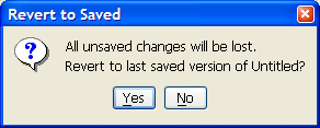
When this menu-item is activated, a small confirmation
dialog box opens, as shown in the figure below. This warning
that all recent changes will be discarded, is needed because
the action can not be undone. Selecting No
cancels the whole action as if you did not select the
menu-item in the first place. Selecting
Yes reloads the last saved file.
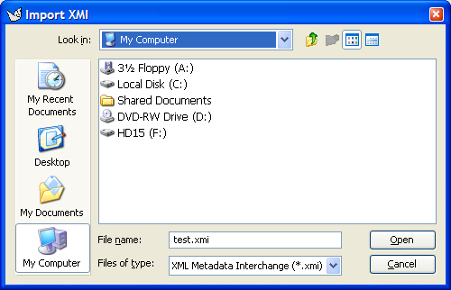
This menu-item allows to load an
UML 1.3 or 1.4 model which was exported by e.g. another tool,
as a XMI file, according the XMI V1.0, V1.1 or V1.2 standard.
The extension of such file should be .xmi.
If the model has been altered (as indicated by the "*" in the titlebar of ArgoUML's window), then activating the "Import XMI..." function is potentionally not the user's intention, since it will erase the changes. Hence a confirmation dialog appears to allow the user to save his work first, or cancel the operation completely.
When the menu is activated, the standard filechooser
appears, see Figure 10.5, “
The dialog for
Import XMI....
”.
Beware the fact that this file will only contain the model,
not any diagram layout. Hence,
the new project will not contain any diagrams.
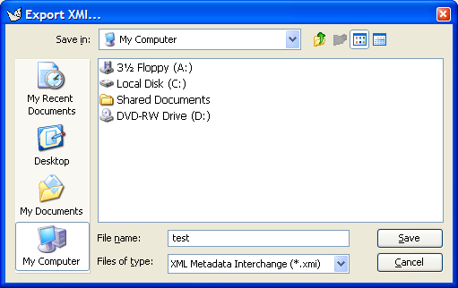
This menu-item allows to save the complete structure of
the UML 1.4 model as a XMI file, according the XMI V1.2 standard.
Beware the fact that this file will only contain the model,
not any diagram layout. Hence, if the XMI file is reloaded
with the File - Open Project... menu, then
the diagrams are lost.
When the menu is activated, the standard filechooser
appears, see Figure 10.6, “
The dialog for
Export XMI....
”.
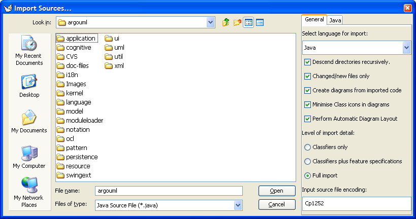
A very powerful feature of ArgoUML is that it can “Reverse Engineer” Java code to yield a class diagram. This sub-menu entry specifies Java code to be imported for reverse engineering.
The dialog box is similar to that for
Open Project (see
Figure 10.2, “
The file selection dialog for
Open Project....
”), but with two
extra tabs placed alongside the directory listing, as shown
in Figure 10.7, “
The file selection dialog for
Import Sources....
”).
Those fields that are the same as
Open Project behave in the same way (see
Section 10.3.2, “
![]() Open Project...
”).
Open Project...
”).
Next to the "All Files" file filter, there is the default filter "Java Source File (*.java)".
The first of the two tabs is labeled
General and is selected by button 1 click on its
tab. It provides a combo box for the language selection (in
V0.18 of ArgoUML only Java can be chosen), and the following
selections:
Descend directories recursively. If enabled (the default), reverse engineering will track through sub-directories for any further Java files. If not it will restrict to the selected directory.Changed/new files only. If enabled (the default), only changed and new files are imported. If not all classes will be replaced.Create diagrams from imported code. If you unselect this, then no diagrams are created, i.e. all data will only be visible in the explorer.Minimise Class icons in diagrams. If enabled, then the attributes and operations compartiments will not be shown in the classes on the generated class diagrams. Note: This item is checked by default, and is overseen by many users, which are then surprised by the result.Perform Automatic Diagram Layout. If selected, then ArgoUML will do its best to layout the generated diagrams automatically. If not, then all items will be placed at the top left corner of the diagram.Level of import detail: Classifiers only / Classifiers plus feature specifications / Full import. The latter is the default.Import source file encoding:. The valueCp1252is often the default. This string represents thecoded character set identifier (CCSID).
The second of the two tabs is labeled
Java and is selected by button 1 click on its tab.
It provides two pairs of radio boxes.
The first radio box allows selection between modeling attributes of Java classes as UML attributes (the default) or as UML associations to the class specified.
The second radio box allows selection between modeling arrays as new datatypes in their own right (the default) or as their base datatype with multiplicity.
This brings up the standard dialog box provided by the operating system to adjust printer paper size, orientation, and other options.
Shortcut Ctrl-P.
This brings up the standard dialog box provided by the operating system allowing the current diagram to be printed out.
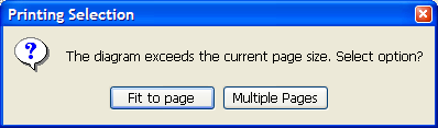
In some cases, when the printing is started, the dialog box of Figure 10.8, “ The diagram exceeds page size dialog. ” appears. Selecting the "Fit to page" button does print the whole diagram fitted on one page by scaling it down. Which might cause all text to be too small to read in case of big diagrams, but it is a quick and easy way to get an usable printout. Selecting the "Multiple pages" option does print unscaled, by dividing the diagram in pieces, on as many pages as needed. Pressing the close button of the dialog does the former option.
![[Warning]](images/warning.png) | Warning |
|---|---|
If the current diagram contains no selected model elements, then the whole diagram is printed. However, if one or more model elements are selected, then only the area they cover is printed! If scaling is selected (by the "Fit to page" choice in the dialog box descibed above), then the scaling is done on basis of the selected model elements only. If scaling is not chosen (or in case it is not needed), then all pages containing a selected model element are printed. |
This menu entry brings up a dialog box allowing the currently selected diagram (in the editing pane) to be saved in one of a number of graphic formats.
The dialog box is identical to that for
Open Project (see
Figure 10.2, “
The file selection dialog for
Open Project....
”), except for the
Files of type:. The chosen filetype
specifies the graphics format used for saving. The filename
is automatically extended with the corresponding ending (if
not entered already). A default filename is generated based
on the diagram name.
The available graphics types are:
GIF image (*.gif)
Encapsulated Postscript file (*.eps)
PNG image (*.png)
Postscript file (*.ps)
Scalable Vector Graphics file (*.svg)
The graphics format that is selected by default is set in the dialog under the menu entry Edit - Settings...
This menu entry brings up a dialog box to select a directory. In this directory, for all diagrams in the current project, a graphics file is generated.
The names of the files are deducted from the diagram names.
The graphics format that is produced
is set in the dialog under the Edit menu
(see Section 10.4.5, “
![]() Settings...
”).
Settings...
”).
This sub-menu presents a radio button selection for notation, i.e. the language in which all textual adornments are shown on the diagrams.
This feature defines the project's notation language.
There are 2 ways to set the notation language:
In the Edit menu, see Section 10.4.5.7, “ Notation Tab ” in the notation tab of the settings dialog, which defines the default notation language for new projects. This choice is stored in the
argo.user.propertiesfile in the.argoumldirectory under the user's home directory.In the File menu, item Notation. This determines how all textual adornments of figures on all diagrams of the current project are shown. This choice is stored in the project file.
The following 2 notations are build in ArgoUML:

UML 1.4. Uses UML notation as the default notation for every modelelement on any diagram.
Java. Uses Java notation as the default notation for every modelelement on any diagram.
The following choices are only available if the corresponding plugin languages are installed.
Cpp.CSharp.PHP.
Besides UML, only Java is partly implemented in V0.22 of ArgoUML.
This menu entry brings up a dialog box, which allows the user to set various options of the currently loaded project.
All settings in this dialog are stored in the project-file together with the model.
In the User tab, you are able to set the following fields:
The first field contains the name of the author or responsible for the current project. By default the name and email of the creator are filled in, so probably you will never need to edit this, but it is possible.
The Project Description field may contain any text that you need to describe the project. By default it is empty.
The "Last saved with ArgoUML" field indicates the version of ArgoUML that was used to save this project (the last time it was saved). This may be usefull if multiple designers have different versions of ArgoUML, which may not be backwards compatible all the time.
In the Profiles tab, you are able change the following settings:
The type of “Stereotype Visualization” for the project, which may be textual, small or with big icons.
The UML profiles which are configured in the project - model elements of these UML profiles may be referenced in the project.
In the Notations tab, you are able to set the following fields:
The first field is a combobox that allows selection of the project's Notation language. By default, it lists UML and Java, but other languages may be added by plugins. See the chapter on Notation for more explanation: Section 12.11, “ Notation ”.
Use guillemots(« ») for stereotypes (clear by default). By default ArgoUML uses pairs of less than and greater than (<< >>) characters for stereotypes. If this box is checked stereotypes on diagrams are shown between true guillemots (« »).This feature is presumably added to ArgoUML because guillemots are poorly supported by various fonts, and if they are present, then they are quite small and poorly visible.
Show visibility(clear by default). If this is selected, then ArgoUML will show the visibility indicators in front of e.g. attributes in the diagram. In UML the notation is "+" for public, "-" for private, "#" for protected, and "~" for package. E.g. for an attribute, it may show:+newAttr : int.Show multiplicity(clear by default). If this is selected, then ArgoUML will show the multiplicity of e.g. attributes in the diagram. In UML notation, the multiplicity is shown between [], such as:+newAttr [0..*] : int. This setting has no impact on showing multiplicity near associationends.Show initial value(clear by default). If this is selected, then ArgoUML will show the initial value of e.g. attributes in the diagram. In UML notation, the initial value is shown e.g. like this:+newAttr : int = 1.Show properties(clear by default). If this is selected, then ArgoUML will show various properties between braces {}. E.g. for an attribute, it may show:+newAttr : int { frozen }.Show types and parameters(set by default). When this checkbox is unmarked, attributes in classes are shown without type indication, and operations are shown without parameters. This feature may be usefull during the analysis phase of your project. If all checkmarks in the Notation Tab are unchecked, then e.g. for an attribute, ArgoUML may show:newAttr. And for an operation:newOperation().Show stereotypes in explorer(clear by default). If this is selected, then ArgoUML will show stereotypes next to the icons of the modelelements in the Explorer, i.e. the tree structure at the left hand side.Default shadow width(set to 1 by default). ArgoUML is able to draw all elements on a diagram with a shadow, for esthetical reasons. Use this setting to adjust the size of the shadow, used when the modelelement is created. The details tab "Presentation" allows to set the shadow per modelelement, after they are created, but ArgoUML V0.22 does not retain this latter change after save and load.
In the Diagram Appearance tab, you are able change the diagrams font.
ArgoUML remembers a few of the most recently saved files, and lists them here, to enable loading then in the most simple way.
The maximum number of files that is listed here, can be
adjusted in the Edit ->
Settings... menu. The list of files is stored in the
argo.user.properties file in the
.argouml directory under the
user's home directory.
Shortcut Alt-F4.
This closes down ArgoUML. A warning message will pop-up if you have a project open with unsaved changes asking if you wish to save it. See Figure 10.13, “ The save changes dialog. ”. The options are:
Yes(save the project and exit ArgoUML);No(do not save the project, but still exit ArgoUML); andCancel(do not save the project and do not exit ArgoUML).The dialog box can also be closed by clicking in the close button in the window border. The effect is the same as selecting "Cancel".