This menu provides support for selecting model elements on the editing pane; removal of model elements from diagrams and the model; and control of user settings.
This sub-menu provides for selection of items on the editing menu. It has the following entries.
Select All(shortcut Ctrl-A). Selects all model elements on the current pane or in the current field. The exact behaviour depends on thecurrent pane(i.e. the last one you clicked in): explorer pane, editing pane, to-do pane, details pane. One rule applies in all cases though: the selection on the diagram (editing pane) and in the explorer are always synchronised.If the editing pane is the
current
              pane
: First everything in the explorer and on the current diagram is deselected, and then everything that is on the current diagram is selected (and if the same items apear in the explorer, then they are also there indicated as selected, because they are always synchronised).If the explorer pane is the
current
              pane
: All visible items in the explorer pane are selected, and non-visible items are deselected.If the to-do pane is the
current
              pane
: All visible items in the to-do pane are selected, and non-visible items are deselected. In fact, this works the same as for the explorer pane, because both are tree structures.If the details pane is the
current
              pane
: The function only works when the cursor is in certain fields, where selecting is possible, e.g. a Name field. In such a case, the Select All function extends the current selection to the whole field contents.
Navigate Back. ArgoUML keeps a record of the model elements that you have been selecting while navigating the model. This button moves you back to the previous one selected. If there are no more previous model elements, the button is grayed out.
Navigate Forward. ArgoUML keeps a record of the model elements that you have been selecting while navigating the model. This button moves you forward to the next one selected (after you have used the Navigate Back button to move back). If there are no more next model elements, the button is grayed out.Invert Selection. This inverts the current selection on thecurrent pane. More exact: everything that was selected is de-selected and everything that was not selected within the current pane is selected.
Shortcut Delete.
This removes the currently selected item(s) from the diagram, but not from the model.
The modelelement can be re-added to the diagram by button 2 click on the modelelement in the explorer, or by dragging it onto the diagram.
Shortcut Ctrl-Delete.
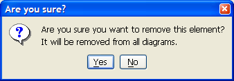
This function deletes the selected item(s) from the model completely.
If the item to be deleted is also present on another diagram than the current one, the dialog box from figure x appears.
This menu-item invokes the same dialog as the button at the top of the explorer. See Section 11.5, “ Configuring Perspectives ”. for a complete description.
This menu entry brings up a dialog box, which allows
the user to set various options that control the behavior of
ArgoUML (see Figure 10.15, “
The dialog for Settings -
Preferences.
”).
These settings are saved persistently for use by subsequent ArgoUML sessions.
ArgoUML has various user specific configurations that can
be set in this dialog box,
or directly on the various panes. Also the main window
size and location is such a setting. Activating this menu
entry causes the information to be saved in the file
argo.user.properties.
The location of this file is in the .argouml directory
under the "users home directory",
which is defined as ${user.home}
, and can be determined as described in
Section 10.4.5.2, “
Environment Tab
”
.
![[Tip]](images/tip.png) | Tip |
|---|---|
This is a text file, which you can edit to configure ArgoUML. |
The options that can be set up on the various tabs are described in the following sections. For each tab there are three buttons at the bottom of the dialog box.
OK. Activating this button (button 1 click) applies the chosen settings and exits the dialog.Cancel. Selecting this button (button 1 click) exits the dialog without applying any settings changed since the lastApply(or since the dialog started ifApplyhas not been used).Apply. Selecting this button (button 1 click) applies the chosen settings and remains in the dialog.
Closing the dialog (with the close button in the top
corner in the border of the window) causes the same effect as
Cancel.
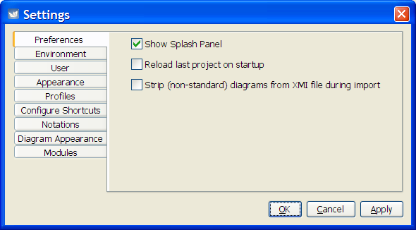
Selecting the Preferences tab
(button 1 click on the tab) gives the following options as
check boxes.
Show Splash Panel(set by default). If enabled ArgoUML will show a small panel with a picture while starting up.Tip The splash panel can be seen by using the Help menu (see Section 10.11.2, “ About ArgoUML ” ).
Reload last saved project on
                startup
(clear by default). Check this item if you always work on the same project, and wish to load it automatically when you start up ArgoUML.Strip (non-standard) diagrams from XMI file during import(clear by default). Checking this item will tell ArgoUML to ignore the "Diagram" elements when importing XMI files.You only need to use this setting, if ArgoUML gives an error while importing your XMI file saying that it encountered unrecognized elements named "Diagram." Some versions of Poseidon are known to create this type of file by default although there's usually an export option to force them to create standard XMI files.
Selecting the Environment tab
(button 1 click on the tab) lists several environmental items.
Note that none of the paths can be altered - these are
just a matter of record.
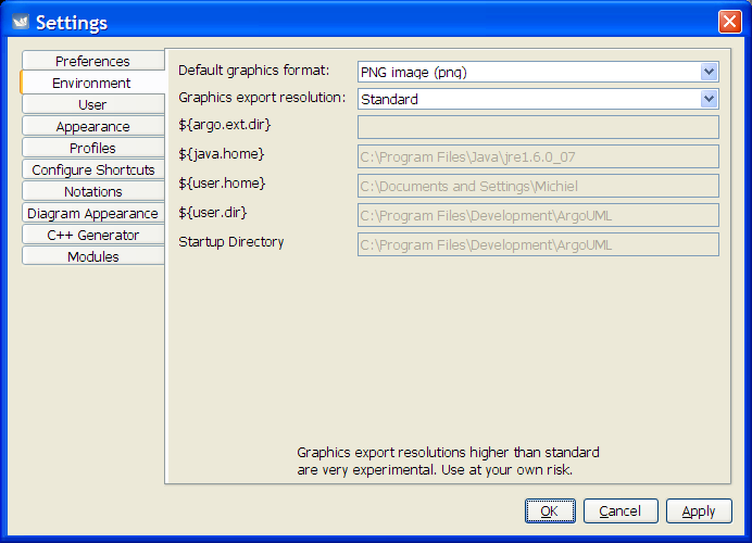
Default Graphics Format. Here you can select the same graphics formats as in the menu Section 10.3.11, “ Export Graphics... ”. The chosen format is selected by default in the Export Graphics and Export All Graphics menu-items.Graphics Export Resolution. This allows you to artificially increase the resolution of produced graphics. The advised setting is "Standard". To be able to use "High" or "Extra High", you usually need to start the Java virtual machine with extra memory.${argo.ext.dir}. The directory holding ArgoUML extensions -by default theextsub-directory of the ArgoUML build directory.${java.home}. The home directory of the Java Runtime Environment (JRE).${user.home}. The user's home directory. Used for storing theargo.user.propertiesfile, under the.argoumldirectory.${user.dir}. The directory from which ArgoUML was started.Startup Directory. The directory in which ArgoUML starts file searches etc.
This tab allows the user to record additional information of use to the system. There are two text boxes provided.
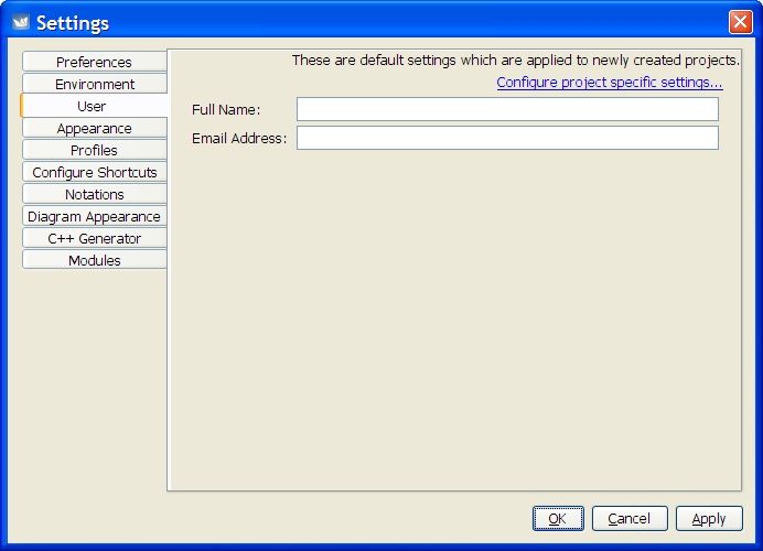
Full Name. Allows the user to record her full name.Email Address. Allows the user to record his Email address.
This information is used when requesting to-do help by Email.
This tab allows the user to specify the LAF (Look And Feel) and theme, i.e. what the complete ArgoUML UI looks like. It comprises the following settings.
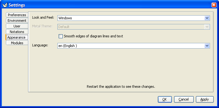
Look and Feel. The choice made here influences the complete User Interface. It only becomes effective when ArgoUML is exited and restarted.Metal Theme. This item is downlighted if the Metal LAF is not chosen. The choice made here influences the complete User Interface. It only becomes effective when ArgoUML is exited and restarted.Smooth edges of diagram lines and text. This feature is known as “anti-aliasing” on certain platforms. It causes diagonal lines to look much less jagged, by making use of several shades of gray. This feature only works if the operating system supports it.
In this tab the user may configure the ArgoUML application settings related to the profiles.
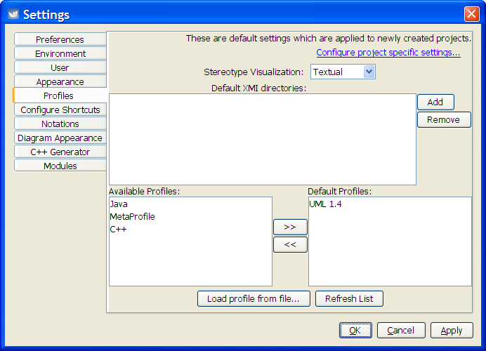
Stereotype Visualization- select to view stereotypes as text, small or big icons.Default XMI directories- allows the user to configure directories where ArgoUML can find the user defined profiles.Default Profiles- select which profiles from the available profiles are configured in new projects by default.
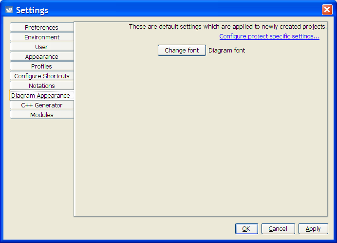
(To Be Written)
This tab allows the user to specify certain notation settings, i.e. how things are shown on diagrams. It comprises the following check boxes.
All settings here, only define the defaults used for new projects. If you want to change the way the diagrams in your current project look, then see the File - Properties menu.
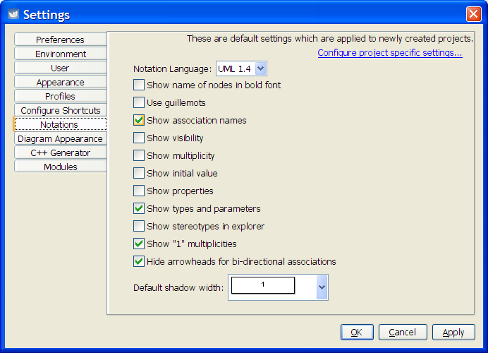
Notation Language( UML 1.4 by default). This feature allows changing the default notation (i.e. language: UML, Java,...) used on the diagrams for new projects. Suppose that a designer indicates that the default notation of a project is Java. When he saves the project, the choice for Java is stored inside the project file. If someone else is viewing the diagram, he will see the Java notation, too. This person can select the UML notation in the File - Notation menu, and see all diagrams in UML language. See Section 10.3.13, “ Notation ”).Show name of nodes in bold font.This feature causes the names of every node (i.e. something drawn with a closed polygon) to be bold.
There is no semantics to showing bold names, but it may make your diagrams look nicer.
Use guillemots(« ») for stereotypes (clear by default). By default ArgoUML uses pairs of less than and greater than (<< >>) characters for stereotypes. If this box is checked stereotypes on diagrams are shown between true guillemots (« »).This feature is presumably added to ArgoUML because guillemots are poorly supported by various fonts, and if they are present, then they are quite small and poorly visible.
Independent of the way they are shown, when entering stereotypes, you can always type real guillemots (if your keyboard supports it) or their << >> equivalents.
Show association names.This feature causes the names of every association to be hidden if not marked.
Show visibility(clear by default). If this is selected, then ArgoUML will show the visibility indicators in front of e.g. attributes in the diagram. In UML the notation is "+" for public, "-" for private, "#" for protected, and "~" for package. E.g. for an attribute, it may show:+newAttr : int.Show multiplicity(clear by default). If this is selected, then ArgoUML will show the multiplicity of e.g. attributes in the diagram. In UML notation, the multiplicity is shown between [], such as:+newAttr [0..*] : int. This setting has no impact on showing multiplicity near associationends.Show initial value(clear by default). If this is selected, then ArgoUML will show the initial value of e.g. attributes in the diagram. In UML notation, the initial value is shown e.g. like this:+newAttr : int = 1.Show properties(clear by default). If this is selected, then ArgoUML will show various properties between braces {}. E.g. for an attribute, it may show:+newAttr : int { frozen }.Show types and parameters(set by default). When this checkbox is unmarked, attributes in classes are shown without type indication, and operations are shown without parameters. This feature may be usefull during the analysis phase of your project. If all checkmarks in the Notation Tab are unchecked, then e.g. for an attribute, ArgoUML may show:newAttr. And for an operation:newOperation().Show stereotypes in explorer(clear by default). If this is selected, then ArgoUML will show stereotypes next to the icons of the modelelements in the Explorer, i.e. the tree structure at the left hand side.Show "1" multiplicities.This feature allows the user to select if he wants to show all multiplicities that are "1" to be shown or not..
Some people consider not showing the multiplicity as "undefined". So, the only way to differentiate between a multiplicity of 1 and an undefined multiplicity, is to mark this checkbox.
Hide arrowheads for bi-directional associations..The UML standard defines different ways to indicate navigability of an association on diagrams. Presentation option 1 is to show all arrows (i.e. you can only navigate in a certain direction if an arrow is drawn), presentation option 2 is to show no arrows at all, and presentation option 3 is to show only an arrow if the association is unidirectional.
Before the release of version 0.26, ArgoUML could only use presentation option 3. Currently, the user can choose between option 1 and 3. Option 2 is not supported.
In the past, option 3 was used most often in other UML tools, but nowadays option 1 is more common.
Default shadow width(set to 1 by default). ArgoUML is able to draw all elements on a diagram with a shadow. Use this setting to adjust the size of the shadow, used when the modelelement is created. The details tab "Presentation" allows to set the shadow per modelelement, after they are created.
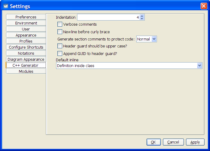
(To Be Written)
This tab shows a list of modules that are installed, which may be enabled or disabled. Since this is a new concept for ArgoUML, it currently contains a list of modules that can not be removed, and a button to test the concept. Pressing this button adds a useless menu-item on the Tools menu, nothing else.
Notice also that this is a "new" modules concept so the old Pluggable modules do not work this way, and are not listed.