Table of Contents
This chapter describes each model element that can be created within a sequence diagram. Note that some sub-model elements of model elements on the diagram may not actually themselves appear on the diagram.
There is a close relationship between this material and
the Properties tab of the details pane (see
Section 13.3, “
Properties Tab
”). That section covers
properties in general, in this chapter they are linked to
specific model elements.
![[Caution]](images/caution.png) | Caution |
|---|---|
Sequence diagrams are not fully developed yet in ArgoUML. Many aspects are not fully implemented, or may not behave as expected. |
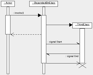
Figure 19.1, “ Possible model elements on a sequence diagram. ” shows a sequence diagram with all possible model elements displayed.
The sequence diagram is still rather under-developed in ArgoUML.
The biggest difficulties are with the actions behind the stimuli. These are purely textual in implementation, and there is no way to link them back to their associated operations or signals.
