Table of Contents
- 20.1. Introduction
- 20.2. State
- 20.3. Action
- 20.4. Composite State
- 20.5. Concurrent Region
- 20.6. Submachine State
- 20.7. Stub State
- 20.8. Transition
- 20.9. Event
- 20.10. Guard
- 20.11. Pseudostate
- 20.12. Initial State
- 20.13. Final State
- 20.14. Junction
- 20.15. Choice
- 20.16. Fork
- 20.17. Join
- 20.18. Shallow History
- 20.19. Deep History
- 20.20. Synch State
This chapter describes each model element that can be created within a statechart diagram. Note that some sub-model elements of model elements on the diagram may not actually themselves appear on the diagram.
There is a close relationship between this material and the Properties Tab of the Details Pane (see Section 13.3, “ Properties Tab ”). That section covers Properties in general, in this chapter they are linked to specific model elements.
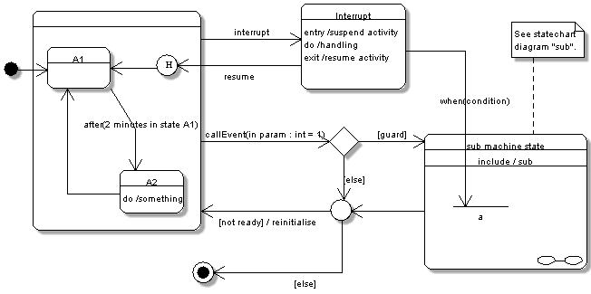
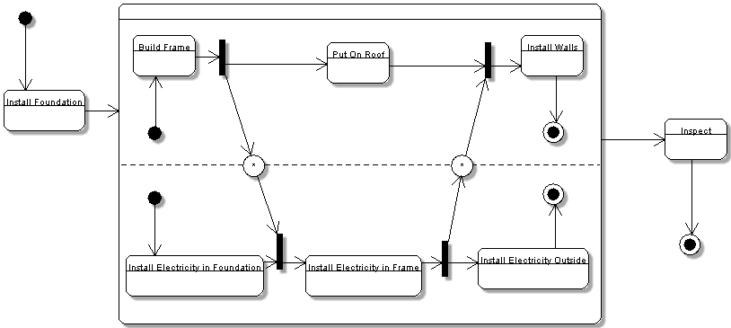
Figure 20.1, “ Statechart diagram model elements 1. ” and Figure 20.2, “ Statechart diagram model elements 2. ” show statechart diagrams with most possible model elements displayed.
The statechart diagrams support the 7 action types defined (CallAtion, CreateAction, DestroyAction, ReturnAction, SendAction, TerminateAction and UninterpretedAction), but there is no way to use the same action more than once. Also, in a few cases, it is not possible to set or select the related elements; e.g.there is no way to select a signal for a SendAction.
Code generation from statechart diagrams is not developed yet.