Table of Contents
This chapter describes each model element that can be created within a Deployment Diagram. Note that some sub-model elements of model elements on the diagram may not actually themselves appear on the diagram.
There is a close relationship between this material and the Properties Tab of the Details Pane (see Section 13.3, “ Properties Tab ”). That section covers Properties in general, in this chapter they are linked to specific model elements.
Within ArgoUML, the deployment diagram is used for both component diagrams (i.e. without instances, showing static dependencies of components) and deployment diagrams (showing how instances of components are handled by instances of nodes at run-time).
![[Caution]](images/caution.png) | Caution |
|---|---|
Deployment diagrams are not fully developed yet in ArgoUML. Some aspects are not fully implemented or may not behave as expected. Notable omissions are the possibility to draw new interfaces and proper stereotyping of the various dependency relationships. |
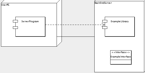
Figure 23.1, “ Possible model elements on a component diagram. ” shows a component diagram with all possible model elements displayed.
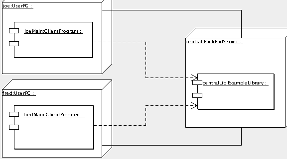
Figure 23.2, “ Possible model elements on a deployment diagram. ” shows a deployment diagram with all possible model elements displayed.
The deployment diagram is generally well drawn, but there are only a subset of the relationships that should be shown available, which restricts the ability to show dynamic behavior of deployed code.
It is not possible to create new interfaces directly on this diagram; they can only be added if they are first created in the model (by drawing them on a class diagram).
It is an inconvenience that the alternative representation of an interface (as a small circle) is not supported.

