| Inkscape » Effects » Modify Path |    |
|---|
The effects in this section all modify an existing path.
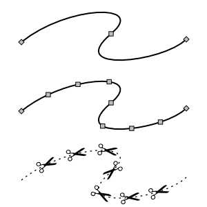
Adds nodes to a path, leaving the shape of the path unchanged. The nodes are added evenly with a minimum specified spacing. Good for creating scissor lines.
Convert regular shapes to paths before applying.
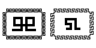
Automates changing the Delimitatori to match the color of the Contorno. The effect makes copies of a Delimitatori in the <defs> section of the SVG file with the appropriate color. This effect is a temporary work-around until the SVG 1.2 standard is finalized. The new standard is expected to simplify matching Delimitatore color with Contorno color.
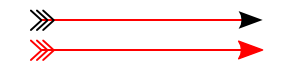
New in v0.46.
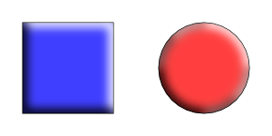
Adds highlights and shadows to simulate 3D objects like buttons. The effect works by adding paths that are blurred via the Gaussian Blur filter and then clipped. The paths have partial transparency, with white for highlights and black for shadows. The effect only works on paths so regular shapes need to be converted first. You may also need to add additional nodes.
Parameters:
Modified slightly in v0.46.
Broken in v0.44 and v0.45.
Can be fixed by removing the line
"self.q['y'] = docheight - self.q['y'] - self.q['height']"
in share/inkscape/extensions/summersnight.py.
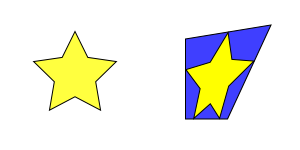
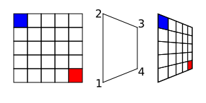
Distorts a path so that the path's original quadro delimitatore is mapped to the edges of a quadrilateral. To use the effect, select the path to transform first, then add the quadrilateral path to the selection (this order is the inverse of what was used before v0.46). Regular shape objects must be converted to a path before transformation.
The effect works on a single path. The
beginning point of the quadrilateral path will determine the
orientation of the transformed image. If the image is inverted
(like looking through a mirror), reverse the direction of the
quadrilateral path with the →
![]() Inverti
(Shift+R) command.
Inverti
(Shift+R) command.
This effect could be used to produce a pseudo-perspective effect. For real perspective, use the Perspective effect.
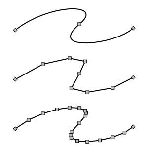
This effect converts selected Bezier curves to an approximation composed of straight-line paths. The number of line segments used is determined by the Flatness parameter. The smaller the Flatness, the more line segments are used.
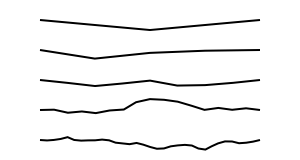
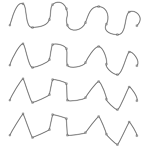
This effect turns a straight-line segment into a crooked segment. It works by finding the midpoint of the line segment, adding a node at that point, and then moving the node a random distance perpendicular to the original path direction. This division routine is called recursively depending on the setting of the Subdivisions entry in the dialog, doubling the number of resulting segments for each increase by one. The Smoothness of the path can also be specified. The magnitude of the perpendicular displacement is a random function with the limits determined by ±(Segment length)/(1+Smoothness).
The effect will also work on a curved path by turning the path into a series of line segments between the path's nodes.
Previously named Radius Randomizer.
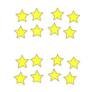
Randomly shift nodes and/or node handles. The Maximum displacement parameter controls the magnitude of the randomization. When the Use normal distribution box is not checked, the magnitude of displacements will be uniformly distributed between zero and the Maximum displacement value (in pixels). When the box is checked, the magnitudes of the displacements will have a Normal (a.k.a. Gaussian or Bell curve) distribution with a standard deviation of 0.5 times the Maximum displacement value. The Normal distribution option may produce more natural-looking variations in a path. In both cases, the direction of the displacement will be random.
Removed in v0.45. Use the L-System effect for creating fractals like Koch's Snowflake. Use the Pattern along Path effect for putting objects along a path.
This effect allows the drawing of figures inspired by Helge von Koch's snowflake. Using the script requires two steps. The first step is to select a path and run the Fractal (Koch) - Load Pattern script. This is the path segment that will be used to replace the paths in the target object.
The second step is to select the target object and to run the Fractal (Koch) script. The object should consist of a path with a number of line segments. Each line segment between adjacent nodes will be replaced by the path loaded in the first step, scaled to fit. Regular shaped objects must be converted to a path first.
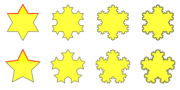
The Koch effect also allows one to produce interesting borders.
New in v0.45.
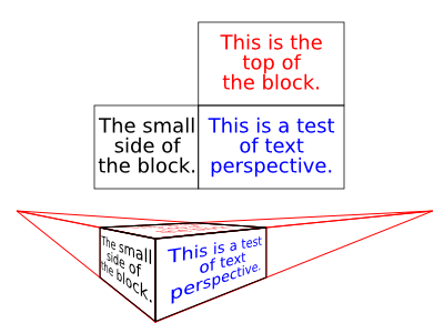
Distorts a path (or a Gruppo of paths) so that the path's original quadro delimitatore is mapped to the edges of a quadrilateral and a perspective effect is applied to the path. To use the effect, select a quadrilateral first, then select the path to transform. Regular shapes and text must be converted to a path before transformation. This effect requires the Numpy (Numerical Python) package.
The beginning point of the quadrilateral path will determine the orientation of the transformed image; in most cases, the quadrilateral path should be started from the lower-left corner and proceed in a clockwise direction.
Renamed Jitter Nodes in v0.45.
New in v0.46.
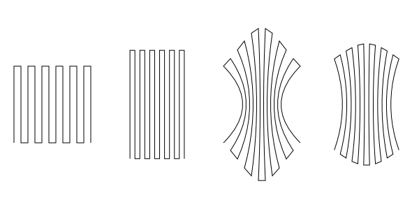
Distorts a path as if the path was stretched vertically or the path was squeezed horizontally. The amount of the distortion is controlled by the Strength and Curve parameters. Adding extra nodes may produce a better result.
Reduces the curvatures of path segments. The amount of straightening can be specified. Behavior 1 moves the node handles toward the nodes, Behavior 2 moves the node handles to a point 1/3 of the distance between the neighboring node away from the node. There is little visual difference between these two options.
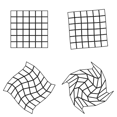
This effect twists an object around a point, like what might happen if you dropped things in whirling water (except the farther away form the center, the greater the displacement for this effect). The amount of «whirling» and the center of the whirl are input parameters (v0.45). Objects must be converted to paths before applying the effect.
![[Nota]](../images/admons/note.png) | Nota |
|---|---|
v0.45: The center is defined in SVG coordinates where the y axis is inverted. To find the correct center, subtract the desired y coordinate from the page height.
v0.46: The center of view is used for the center of the
whirl. To whirl around the center of an object, select the
object and then use → →
|
| |  | |
| Images |  | Raster |
© 2005-2008 Tavmjong Bah. | Get the book.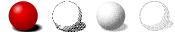 |