Grouped together in the Firewall Menu are some of the core functions of IPCop which controls how traffic flows through the firewall.
These are:
External Access (Controls remote administration of IPCop from the Internet)
Blue Access (Connecting a Wireless Access Point to IPCop)
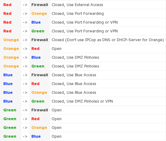
The table below summarizes the default firewall settings and the steps required to open or control access between them.
In v1.4 there is a new file for users to make their own changes to
firewall rules. Have a look inside the file
/etc/rc.d/rc.firewall.local
It is called by /etc/rc.d/rc.firewall,
and for manual use, the usage is:
$/etc/rc.d/rc.firewall.local {start|stop|reload}
Note
The reload option was added in v1.4.2, and further modified in v1.4.6, but changes were not included in Official Updates, to avoid overwriting Users' existing modifications.
There are also specific chains for Users' use, called
CUSTOMINPUT,
CUSTOMOUTPUT and
CUSTOMFORWARD as per version 1.3.
Introduced in version 1.3, there is also the file
/etc/rc.d/rc.local which is run when
IPCop boots, and can contain your own specific commands
to run at boot time, for instance to setup an internal modem.
Neither of these files will be affected by Official Updates, and are included in the set of files saved when you backup the system files.
This subsection allows you to configure the Port Forwarding settings for IPCop. This is 100% optional, so you may safely ignore this section if you do not wish to make use of this feature.
Firewalls prevent externally initiated requests from accessing the protected system. However, sometimes, this is too strict a situation. For example, if one is running a web server, then any requests to that web server by users outside the protected network will be blocked by default. This means that only other users on the same internal network can use the web server. This is not the normal situation for web servers. Most people want outsiders to be able to access the server. This is where Port Forwarding comes in.
Port Forwarding is a service that allows limited access to the internal LANs from outside. When you set up your server, you can choose the receiving or “listening” ports on the internal network machines. This is done differently depending on which software is being used. Please refer to the documentation that came with your servers to set up the ports on those servers.
Once those receiving ports are ready, you are ready to enter information into the AW on IPCop. The TCP/UDP drop down list allows you to choose which protocol this rule will follow. Most regular servers use TCP. Some game servers and chat servers use UDP. If the protocol is not specified in the server documentation, then it is usually TCP. Source port is the port to which the outsiders will connect. In most cases, this will be the standard port for the service being offered (80 for web servers, 20 for FTP servers, 25 for mail servers, etc.) If you wish, you may specify a range of ports to forward. To specify a range use the “:” character between two port numbers, lowest number first. Destination IP is the internal IP address of the server (for example, you may have your web server on 192.168.0.3). Destination Port is the port that you chose when you set up your server in the first paragraph. The SourceIP dropdown menu allows you to choose which Red IP this rule will affect. IPCop has the capability of handling more than one Red IP. If you only have one Red IP set up, then choose Default IP.
The Port Forwarding interface was re-written for version 1.3.0. It is quite different from earlier versions. However, please note that the port numbers used for a particular service have not changed, and you should still refer to these above.
The External Access page has NO affect on the GREEN or ORANGE networks. It is there to allow you to open ports to the IPCop box itself and not the GREEN or ORANGE networks.
How do you open up external access then? It is combined into the Port Forward page - there is a field on the page labeled:
'Source IP, or network (blank for "ALL"):'
This is the field that controls external access - if you leave it BLANK, your port forward will be open to ALL INTERNET ADDRESSES. Alternatively if you put an address or network in there, it will be restricted to that network or Internet address.
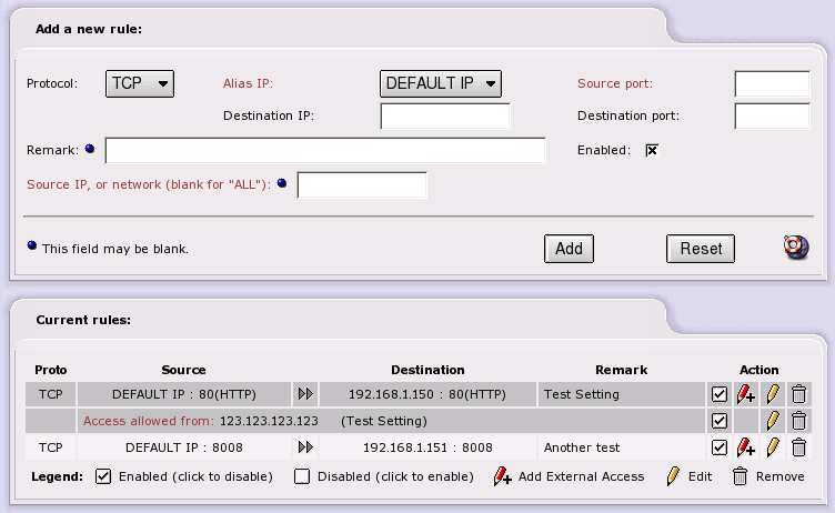
You can have more than one external address - after you have created the port forward entry, it will appear in the table. If you wish to add another external address, click the Red Pencil with the Plus sign next to the entry, the entry screen at the top of the page will change (it will load values from the port forward) and allow you to enter an external IP address or network.
When added you will now notice that there is a new entry under the port forward in the table.
Other things to note:
We support the GRE protocol.
You can have port ranges and wildcards. Valid wildcards are:
* which translates to 1-65535
85-* which translates into 85-65535
*-500 which translates into 1-500
Valid characters to separate a port range are “:” or “-”. Note that - will be modified to a “:” even though it will be displayed as a “-” on the screen.
You only need to enter the first source port, the destination will be filled in for you.
You can edit a record by clicking on the Yellow Pencil icon in the Action column, and until you hit the update button, nothing changes and nothing is lost.
When you are editing a record, you will see the record highlighted in yellow.
To delete a record, click on the Trash Can icon on the right hand side of the Action column.
Ports ranges cannot overlap each other.
Individual ports cannot be placed in the middle of a range i.e. if you have 2000-3000 already set up and then try to forward port 2500, it will give you an error. You cannot forward the same port to several machines.
Reserved ports - on the main Red Address (DEFAULT IP) some ports are reserved for IPCop to do its business, they are 67, 68, 81, 222, and 445.
When you edit a port forward, there will be an extra check box labeled 'Override external access to ALL'. This is used as a quick and dirty way to open a port to ALL Internet addresses for testing or whatever your reasons. This was a user request.
If you have a port forward with multiple external accesses, when you delete all of the external accesses, the port becomes open to ALL addresses, be careful of this one.
There is a Shortcut to enable or disable a port forward or external access - click on the “Enabled” icon (the checkbox in the Action column) for the particular entry you want to enable or disable. The icon changes to an empty box when a rule is disabled. Click on the checkbox to enable it again. Note: when you disable the port forward, all associated external accesses are disabled, and when you enable the port forward, all associated external accesses are enabled.
This subsection allows you to configure the External Access settings for IPCop machine itself. This is 100% optional, so you may safely ignore this section if you do not wish to make use of this feature.
From v1.3.0 onwards, External Access only controls access to the IPCop box. It has no affect on the Green, Blue or Orange network access. That is now controlled in the Port Forwarding section, see above.
If you wish to maintain your IPCop machine remotely, you should specify TCP port 445, https. If you have enabled ssh access, you can also enable TCP port 222, ssh.
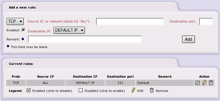
The TCP/UDP drop down list allows you to choose which protocol this rule will follow. Most regular servers use TCP. If the protocol is not specified in the server documentation, then it is usually TCP. Source IP is the IP address of an external machine you give permission to access your firewall. You may leave this blank, which allows any IP address to connect. Although dangerous, this is useful if you want to maintain your machine from anywhere in the world. However, if you can limit the IP addresses for remote maintenance, the IP addresses of those machines or networks that are allowed access, should be listed in this box. Destination Port is the external port that they are allowed to access, i.e. 445. The Destination IP dropdown menu allows you to choose which Red IP this rule will affect. IPCop has the capability of handling more than one Red IP. If you only have one Red IP set up, then choose Default IP.
Once you have entered all the information, click the Enabled box and press . This will move the rule to the next section, and list it as an active rule.
Current rules lists the rules that are in effect. To remove one, click the “Trash Can” icon. To edit one, click the “Yellow Pencil” icon.
To enable or disable a rule - click on the “Enabled” icon (the checkbox in the Action column) for the particular entry you want to enable or disable. The icon changes to an empty box when a rule is disabled. Click on the checkbox to enable it again.
This subsection allows you to configure the DMZ Pinholes settings for IPCop. This is 100% optional, so you may safely ignore this section if you do not wish to make use of this feature.
This page will only be visible if you have installed and configured an Orange or a Blue network interface card.
A DMZ or Demilitarized Zone (Orange zone) is used as a semi-safe interchange point between the external Red Zone and the internal Green zone. The Green zone has all your internal machines. The Red zone is the Internet at large. The DMZ allows them to share servers without allowing undue access to the internal LAN by those in the Red Zone.
For example, suppose that your business has a web server. Certainly, you want your customers (those in the Red zone) to be able to access it. But suppose you also want your web server to be able to send customer orders to employees in the Green Zone? In a traditional firewall setup, this wouldn't work, because the request for access to the Green zone would be initiating from outside the Green zone. You certainly do not want to give all your customers direct access to the machines on the Green side, so how can this work? By using the DMZ and DMZ pinholes.
DMZ pinholes give machines in the Orange (DMZ) zone limited access to certain ports on Green machines. Because servers (the machines in the Orange zone) have to have relaxed rules with respect to the Red zone, they are more susceptible to hacking attacks. By only allowing limited access from Orange to Green, this will help to prevent unauthorized access to restricted areas should your server be compromised.
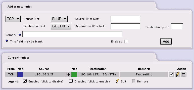
The TCP/UDP drop down list allows you to choose which protocol this rule will follow. Most regular servers use TCP. Some game servers and chat servers use UDP. If the protocol is not specified in the server documentation, then it is usually TCP. Use the protocol specified on the Port Forwarding page.
Source Net is a drop down menu that shows the available source networks on the machine.
Source IP is the IP address of the machine that you wish to give permission to access your internal servers.
Destination Net is a drop down menu that shows the available networks on the machine.
The Destination IP is the machine in the Green or Blue zone that will receive the request.
Destination Port is the port on the machine that will be listening for the request.
Once you have entered all the information, click the Enabled box and press . This will move the rule to the next section, and list it as an active rule.
Current rules lists the rules that are in effect. To remove one, click the “Trash Can” icon. To edit one, click the “Yellow Pencil” icon.
To enable or disable a rule - click on the “Enabled” icon (the checkbox in the Action column) for the particular entry you want to enable or disable. The icon changes to an empty box when a rule is disabled. Click on the checkbox to enable it again.
This subsection allows you to configure which Wireless Access Points on the Blue network can connect to IPCop. This is 100% optional, so you may safely ignore this section if you do not wish to make use of this feature.
Note
This page will only be visible if you have installed and configured a Blue network interface card.
To setup Blue Access do the following:
Use a supported Ethernet card to setup the Blue interface.
Connect an Access Point to that Ethernet card. (Use the LAN Ethernet port on the AP, if you have a choice of ports).
You can use DHCP to serve dynamic or static addresses on Blue, although static is preferred for security of MAC addresses. Refer to the DHCP Server section for more information on configuring static leases.
If you only need to provide access for http traffic on the Blue network to the Internet (Red network), just add the IP Address or the MAC Address of the Wireless Router, or the individual wireless connected devices if you are using an Access Point, via the web page shown below. You have to enter at least one MAC or one IP Address per device. Optionally, you can enter both MAC and IP Address for a device.
An Access Point behaves like an Ethernet hub, and IPCop serves out DHCP leases through it to wireless devices. A Wireless Router does NAT, serves out DHCP on it's own subnet, and has it's own access controls.
Note
Your Access Point must support DHCP passthrough if you want IPCop to serve DHCP leases through it to your Wireless Network. Not all devices support this feature in Access Point “mode” (Netgear WG614, for instance).
You will be able to view IPCop's web interface from a computer on the Blue network, but you will not be able to connect to the Green network without some additional work.
To connect to the Green network from the Blue network, you have to either:
Use the DMZ Pinholes page and shoot bullet holes through the Blue interface for your services, or:
Setup a VPN for your road-warriors on Blue to provide access.
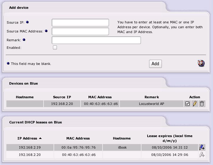
In the Add Device section you input the IP Address or the MAC Address of a wireless Access Point, or any device on the Blue network that you want to connect to the Internet through IPCop.
You have to enter at least one MAC or one IP Address per device.
If you use DHCP on the Blue Network, and want to allow any device to connect and access the Red Network, you must add an entry for every IP address in your DHCP range to this list. Leave the MAC Address field empty when adding each IP Address.
Conversely, if you want to restrict access to known devices, add the MAC address of each device, and leave the IP Address field empty. That will allow listed devices to connect regardless of the DHCP lease they receive.
Once you have entered all the information, click the Enabled box and press . This will move the entry to the next section, and list it as enabled.
The Devices on Blue section lists the current entries. To remove one, click the “Trash Can” icon. To edit one, click the “Yellow Pencil” icon.
To enable or disable an entry, click on the “Enabled” icon (to the left of the Yellow Pencil) for the particular entry you want to enable or disable. The icon changes to an empty box when a device is disabled. Click the checkbox to enable it again.
If DHCP is enabled for the Blue network, the Current DHCP leases on Blue section will be displayed.
This provides a quick way of adding wireless devices to the list. You just have to click on the “Blue Pencil” icon for a device to be added to the list of enabled devices. You can then edit the entry, if necessary, by clicking on the “Yellow Pencil” icon, as before.
This subsection allows you to configure some firewall behaviour. This is 100% optional, so you may safely ignore this section if you do not wish to make use of this feature.
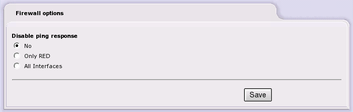
Disable ping response
- IPCop responds to ping requests on any interface. This is the default behaviour.
- IPCop does not respond to ping requests on the Red Interface.
- IPCop does not respond to any ping requests on any interface.
To save changes, press the button.