Sometimes one wants to add simple drawing elements to a chart, such as circle an arrowhead or comment, dots or other shapes. Msc-generator supports naturally only limited drawing capabilities, but here they are.
Arbitrary vertical space can be added using the vspace command.
vspacenumber[attributes];vspace:label[attributes];
In the first form the vertical space is specified as a number in points.
In the secod form, the height of the given label will be used. This command
also has a specific attribute, called compressable, which specifies
if the space should be ignored if compress is on. It defaults to no.
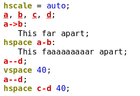
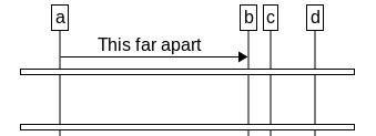
Horizontal spacing between the entities can be controlled either via the
pos and relative entity attributes or can be made fully automatic
by specifying hscale=auto;, see Entity Positioning and
Chart Options.
The hspace command is useful in the latter case to force a certain
horizontal distance between two (not necessarily neighbouring) entity. The
space can be larger than the one specified with hspace if the layout
requires so, but never smaller.
hspaceentity-entitynumber[attributes];hspaceentity-entity:label[attributes];hspace left commentnumber[attributes];hspace right commentnumber[attributes];
The syntax is similar to that of the vspace command, both a number or
a label can be used to specify the horizontal distance. Before the distance,
the two entities need to be specified. Any one can be omitted, in this case the
distance is proscribed between the edge of the chart and the entity[36]. Two special versions of the hspace command exist to specify
the spacing for the comments on the right and left sides.
The hspace command can be specified anywhere in the file with the same
effect.
 |
 |
Currently Msc-generator can draw circles (ellipses), ellipses (three dots) and rectangles (optionally with text) or just plain text. We call these symbols.
symbolarc|rectangle|...|textmarker-markerhpos1hpos2[attributes];
By specifying either arc, rectangle, ... or text
after the symbol keyword one instructs Msc-generator to draw
one circle/ellipsis, rectangle, ellipses or just text[37], respectively.
The vertical position of the symbols can be specified two ways. Either they are in-line, which means they occupy space and the layout engine takes them into account when laying out entities above below. In this case symbols will be drawn at the vertical position where they are specified in the file, just like any other element (except verticals). To achieve in-line placement, just omit the markers (and the dash in-between) from the above syntax.
Otherwise it is possible to specify the vertical position where the symbol should appear. This can be done via markers, similar as for verticals, see Verticals. In this case however, the layout engine will ignore the symbol and it will be drawn either behind or in front of other elements.
The vertical size of the object can be specified two ways. Either you specify two
markers (as above), in which case the symbol will vertically span from one to the
other; or you omit one of the markers, in which case the ysize attribute
specifies the height (in points)[38].
If the dash is in front of the marker, the
bottom of the symbol will be aligned with the marker. If the dash is after the
marker, then the marker designates the top of the symbol.
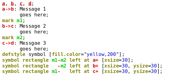
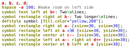
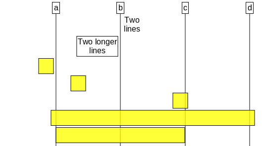
In the example below we see three rectangles. One stretches between two markers, the second is bottom aligned, while the third is top aligned.
 |
 |
The horizontal position of the symbol is specified via one or two horizontal position specifiers. They specify the horzontal position of either the left or right edge of the symbol or of its center. This is governed by the first keyword
left|center|rightatentity-entity[number]left|center|rightatentity--left|center|rightatentity-left|center|rightatentity[number]left|center|rightatentity+left|center|rightatentity++
Then, after the at keyword one specifies either one entity with
additional modifiers or two entities. In the former case
the horizontal position will be at the middle of the entity’s line or somewhat left
or right of it depending on the modifiers. In the latter the horizontal position
will be between the two entities. Two of the forms can also take a number, which
is interpreted as pixels and will shift the position to the right for positive
values and to the left for negative values.
If you specify two such horizontal position specifiers one after the other, they
describe both the placement of the symbol and its width. If you specify one,
the width of the symbol can be specified using the xsize
attribute[39].
This may sound a bit complicated, so here is an example with 5 in-line symbols.
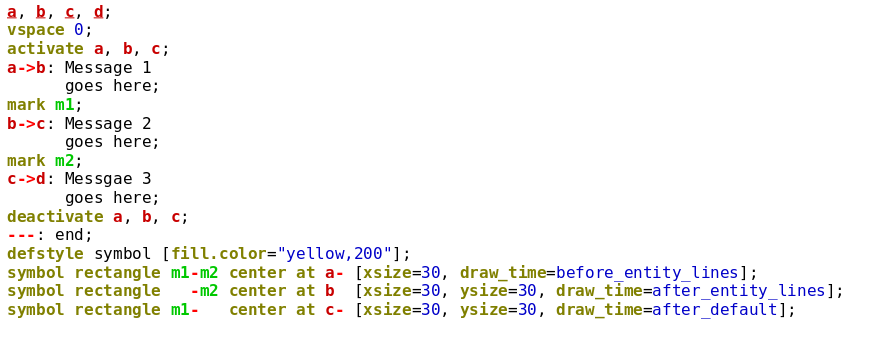
Whether the symbol is drawn behind or in front of other elements can be controlled
by the ‘draw_time’ attribute. It can take the following values.
before_entity_linesElements with this property will be drawn before the entity lines are laid out in the order as they are specified in the chart description.
after_entity_linesElements with this property will be drawn just after the entity lines are laid out, but before regular elements are drawn.
defaultThis is the default, elements with no
draw_timewill be drawn this time in the order as specified in the chart description.after_defaultElements with this property will be drawn last, after all the above elements in the order as they are specified in the chart description.
Note that from v3.3.4 any element can specify the draw_time attribute. It
will not impact thet layout only the drawing order (what is called the
z-order).
 |
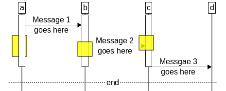 |
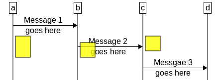
As you can see the first (leftmost) rectangle was drawn below the entity lines, the second (middle) one between the entity lines and the arrows, while the last (rightmost) one was drawn on top of the arrows.
Finally we show a few examples of how symbols may be used.
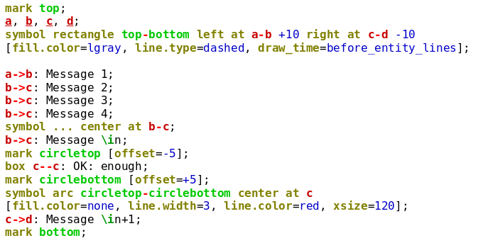
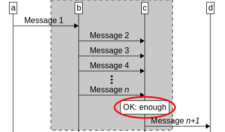
Sometimes one just wants to add some text to the diagram and in this case the symbol text
syntax may be a bit heavy and difficult to do. As an easier way to do that Msc-generator offers the
text at command.
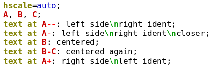
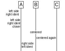
text atpos[attributes]: label;
This draws just text (you must specify a label) at the vertical position the command is written. You can use simple horizontal position specifiers, like below to place the text centered in-between two entities; left of an entity, centered around an entity or right of an entity. You can optionally specify a number, which will be interpreted as a pixel offset to the right (negative value to the left.)
entity-entity[number]entity-- [number]entity- [number]entity[number]entity+ [number]entity++ [number]
You can influence the default appearance via the text built-in style.
 |
 |
[36] Note
that the edge will not be the physical edge, merely the invisible line from which
arrows connect to when only one entity is specified, such as a->; or
->a;.
[37] We have to note
that text is just syntactic sugar for a rectangle with no line or
fill. Rectangles can also contain text.
[38] In case of rectangles
and text, you can use the natural size of the label you specify as the height of
the symbol by omitting the ysize attribute.
[39] Similar to height, in case of rectangles
and text, you can use the natural size of the label you specify as the width of
the symbol by omitting the xsize attribute.