Table of Contents
- 16.1. MySQL Workbench Editions
- 16.2. Installing and Launching MySQL Workbench
- 16.3. Getting Started Tutorial
- 16.4. The Home Screen
- 16.5. SQL Development
- 16.6. Data Modeling
- 16.6.1. Open an Existing EER Model
- 16.6.2. Create new EER Model
- 16.6.3. Create EER Model from Existing Database
- 16.6.4. Create EER Model from SQL Script
- 16.6.5. Model Editor
- 16.6.6. EER Diagram Editor
- 16.6.7. Working with Models
- 16.6.8. Modeling Tutorials
- 16.6.9. Printing
- 16.6.10. MySQL Workbench Schema Validation Plugins (Commercial Version)
- 16.6.11. Customizing DBDoc Model Reporting Templates
- 16.7. Server Administration
- 16.8. Extending Workbench
- 16.9. Keyboard Shortcuts
- 16.10. MySQL Workbench FAQ
MySQL Workbench provides a graphical tool for working with MySQL Servers and databases. MySQL Workbench fully supports MySQL Server versions 5.1 and above. It is also compatible with MySQL Server 5.0, but not every feature of 5.0 may be supported. It does not support MySQL Server versions 4.x.
MySQL Workbench provides three main areas of functionality:
SQL Development
Data Modeling
Server Administration
This section provides a brief overview of this functionality.
SQL Development: Enables you to create and manage connections to database servers. As well as allowing you configure connection parameters, MySQL Workbench provides the capability to execute SQL queries on the database connections using the built-in SQL Editor. This functionality replaces that previously provided by the Query Browser stand-alone application.
Data Modeling: Enables you to create models of your database schema graphically, reverse and forward engineer between a schema and a live database, and edit all aspects of your database using the comprehensive Table Editor. The Table Editor provides easy-to-use facilities for editing Tables, Columns, Indexes, Triggers, Partitioning, Options, Inserts and Privileges, Routines and Views.
Server Administration: Enables you to create and administer server instances. This functionality replaces that previously provided by the MySQL Administrator stand-alone application.
MySQL Workbench is available in two editions. The Community Edition and the Standard Edition. The Community Edition is available free of charge. The Standard Edition provides additional Enterprise features, such as database documentation generation, at low cost.
The Community Edition (OSS)
The Community Edition is the foundation of all MySQL Workbench editions—versions that are currently available or those that will become available in the future. All editions of MySQL Workbench are based on the Community Edition and all future improvements to the base framework and feature set will be included in this version. The Community Edition is a full feature product that puts a powerful database management tool into the hands of the MySQL community.
The Standard Edition
The Standard Edition is a commercial extension that builds on top of the OSS Edition and adds modules and plugins, allowing for an optimized work flow. The highlights of this edition are:
MySQL Specific Schema Validation
Model Validation
General Schema Validation
DBDoc
DBDoc provides the following features:
Document complex database schemata
Document all SQL object types
Document output available in different file formats
A comparison of edition features can be found at MySQL Workbench Developer Central.
MySQL Workbench is available for the following platforms:
Windows
Linux
Mac OS X
Binary distributions of MySQL Workbench are avaliable for the above
platforms. Source code distributions are also available as a
tar.gz package, or an RPM package.
The following sections explain the installation process for each of these platforms.
MySQL Workbench requires a current system to run smoothly. The minimum hardware requirements are:
CPU: Intel Core or Xeon 3GHz (or Dual Core 2GHz) or equal AMD CPU
Cores: Single (Dual/Quad Core is recommended)
RAM: 4 GB (6 GB recommended)
Graphic Accelerators: nVidia or ATI with support of OpenGL 1.5 or higher
Display Resolution: 1280×1024 is recommended, 1024×768 is minimum.
The following operating systems are officially supported:
Windows 7 (64-bit, Professional level or higher)
Mac OS X 10.6.1+
Ubuntu 9.10 (64bit)
Ubuntu 8.04 (32bit/64bit)
For convenience the following builds are also available:
Windows XP SP3, Vista
Mac OSX (10.5 and 10.6) Intel
Ubuntu 8.04 (i386/x64)
Ubuntu 9.04 (i386/x64)
Fedora 11 (i386/x64)
MySQL Workbench also has the following general requirements:
The Microsoft .NET 3.5 Framework.
Cairo 1.6.0 or later
glib-2.10
libxml-2.6
libsigc++ 2.0
pcre
libzip
For convenience the Windows libraries are available as the download “Dependencies for Compiling in Windows”.
On start up, the application checks the OpenGL version and selects between software and hardware rendering. To determine the rendering method that is being used, open the menu and choose the submenu.
- 16.2.3.1. Installing MySQL Workbench on Windows
- 16.2.3.2. Launching MySQL Workbench on Windows
- 16.2.3.3. Uninstalling MySQL Workbench on Windows
- 16.2.3.4. Installing MySQL Workbench on Linux
- 16.2.3.5. Launching MySQL Workbench on Linux
- 16.2.3.6. Uninstalling MySQL Workbench on Linux
- 16.2.3.7. Installing MySQL Workbench on Mac OS X
- 16.2.3.8. Launching MySQL Workbench on Mac OS X
- 16.2.3.9. Uninstalling MySQL Workbench on Mac OS X
The procedure for launching MySQL Workbench depends on the platform. Generally, there are two ways to launch MySQL Workbench from the command line and from the graphical user interface of the host operating system. Using the command-line launching facility is useful when you want to customize some aspects of the way MySQL Workbench operates. Launching MySQL Workbench for each of the supported platforms is described in the following sections.
In addition to platform-specific command line options, MySQL Workbench has the following command line options:
--admin- Launch MySQL Workbench and load the server instance specified.instance--query- Launch MySQL Workbench and load the connection specified.connection--model- Launch MySQL Workbench and load the model specified.modelfile--script- Launch MySQL Workbench and run the script specified.script--run- Launch MySQL Workbench and run the code snippet specified.code--quit-when-done- quits MySQL Workbench after --script or --run finishes.
MySQL Workbench may be installed using the Windows installer file or it may be installed manually from a ZIP file.
Installing MySQL Workbench Using the Installer
MySQL Workbench can be installed using the Windows Installer
(.msi) installation package. The MSI package
bears the name
mysql-workbench-,
where version-win32.msiversion indicates the
MySQL Workbench version number.
Installing MySQL Workbench using the installer requires either Administrator or Power User privileges. If you are using the ZIP file without an installer, you do not need Administrator or Power User privileges.
Improving the MySQL Installation Wizard depends on the support and feedback of users. If you find that the MySQL Installation Wizard is lacking some feature important to you, or if you discover a bug, please report it in our bugs database. To do this use the option under the menu.
To install MySQL Workbench, right-click the MSI file and select the option from the pop-up menu, or simply double-click the file.
In the Setup Type window you may choose a
CompleteorCustominstallation. To use all features of MySQL Workbench choose theCompleteoption.Unless you choose otherwise, MySQL Workbench is installed in
C:\, where%PROGRAMFILES%\MySQL\MySQL Workbench 5.1edition_type\%PROGRAMFILES%is the default directory for programs for your locale. The%PROGRAMFILES%directory may beC:\Program FilesorC:\programme.
Installing from the ZIP File
If you are having problems running the installer, as an
alternative, you can download a ZIP file without an installer.
That file is called
mysql-workbench-.
Using a ZIP utility, unpack it to the directory of your choice.
You may also want to create a shortcut on your desktop or the
quick launch bar.
version-win32.zip
To install using the ZIP file, download the ZIP file to a convenient location and decompress the file. You can place the resulting directory anywhere on you system. You do not need to install or configure the application before using it.
To start MySQL Workbench on Windows select , , and then select MySQL Workbench.
You may also start MySQL Workbench from the command line. To view the available command-line options, issue the command MySQLWorkbench -help | more from the MySQL Workbench installation directory. You will see the following output:
MySQL Workbench 5.1.12 OSS. (C) 2006-2009 by Sun Microsystems.
All rights reserved.
Usage: MySQLWorkbench [options] [model file]
Options
  -help (-h) ...... Print this output
  -open filename .. Open the given filename at startup
  -nologo ......... Do not display the splash screen
  -verbose (-v) ... Print verbose output in the GRT Shell
  -version ........ Print the version information
  -grtversion ..... Print the GRT version information
  -swrendering .... Force the canvas to use software rendering instead of OpenGL
  -log ............ Instruction to save messages (other debug info) to file
The MySQL Workbench version number is displayed followed by a usage
message and then the options. Use the
-swrendering option if your video card does not
support OpenGL 1.5. The -version option can be
used to display the MySQL Workbench version number. The
-grtversion can be used to display the GRT
shell version number. The other options are self-explanatory.
When using command-line options that display output to a
console window, namely -help and
-version, be sure that you pipe the output
through the more command otherwise nothing
will be displayed.
The method for uninstalling MySQL Workbench will depend on how you install MySQL Workbench in the first place.
Rmoving MySQL Workbench when installed Using the Installer
To uninstall MySQL Workbench, open the Control Panel and Choose Add or Remove Programs. Find the MySQL Workbench entry and choose the button. Doing this will remove MySQL Workbench.
Any modules added to the
C:\Program Files\MySQL\MySQL Workbenchdirectory will not be deleted.version\modules
It is not possible to remove MySQL Workbench from the command line if you have installed MySQL Workbench using the installer. Although you can manually remove some of the compoentns There is no command-line option for removing MySQL Workbench.
Removing the MySQL Workbench directory manually will not remove all the files belonging to MySQL Workbench.
When installed from a ZIP file
If you installed MySQL Workbench using a ZIP file, to remove MySQL Workbench you can just delete the MySQL Workbench directory.
If you installed any additional modules within the
modules directory and you want to keep
them, make sure you copy those modules to a different
directory before deleting the MySQL Workbench directory.
There are several binary distributions of MySQL Workbench available for Linux. These include:
Fedora 10 amd64 (RPM)
Ubuntu 8.04 i386 (DEB)
Ubuntu 8.10 amd64 (DEB)
In addition to the binary distributions, it is also possible to
download the MySQL Workbench source code as a
tar.gz or RPM package.
Check the MySQL Workbench download page for the latest packages.
The procedure for installing on Linux depends on which Linux distribution you are using.
Installing DEB packages
On Ubuntu, and other systems that use the Debian package scheme, you can install MySQL Workbench using a command such as:
shell> sudo dpkg -i package.deb
Note that
package.debmysql-workbench-oss-,
where version_i386.debversion is the MySQL Workbench
version number.
You may be warned that certain libraries are not available, depending on what you already have installed. Install the required libraries and then install the MySQL Workbench package again.
Installing RPM packages
On RedHat-based systems, and other systems using the RPM package format, MySQL Workbench can be installed by a command such as:
shell> sudo rpm -i package.rpm
Again, note that
package.rpmmysql-workbench-oss-,
and version-1fc10.x86_64.rpmversion is the MySQL Workbench
version number.
Once MySQL Workbench has been installed it can be launched by selecting , , from the main menu.
MySQL Workbench can also be launched from the command line on Linux. Type the command:
shell> /usr/bin/mysql-workbench --help
This will display the available command-line options:
mysql-workbench [<options>] [<model file>]
Options:
  --force-sw-render       Force Xlib rendering
  --force-opengl-render   Force OpenGL rendering
  --help, -h              Show command line options and exit
The procedure for uninstalling MySQL Workbench on Linux depends on the packe you are using.
Uninstalling DEB packages
For Debian packages the command is:
shell> sudo dpkg -r mysql-workbench-oss
This does not remove the configuration files. If you wish to also remove the configuration files use:
shell> sudo dpkg --purge mysql-workbench-oss
Uninstalling RPM packages
To uninstall RPM packages use:
shell> sudo rpm -e mysql-workbench-oss
This does not remove the configuration files.
MySQL Workbench is available for Mac OS X and is distributed as a
DMG file. The file is named
mysql-workbench-oss-,
where version-osx10.5-i686.dmgversion is the MySQL Workbench
version.
To install MySQL Workbench on Mac OS X, simply download the file. Double-click the downloaded file. You will be presented with the installation screen:
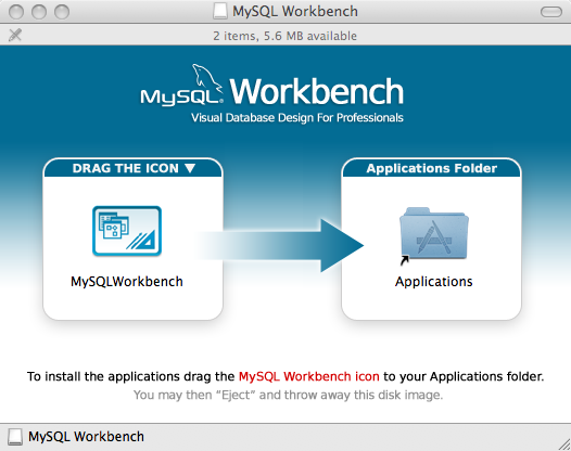
Drag the MySQL Workbench icon onto the Application icon as instructed. MySQL Workbench is now installed.
You can now launch MySQL Workbench from the Applications folder.
To launch MySQL Workbench on Mac OS X, simply open the Applications folder in the Finder, then double-click MySQL Workbench.
It is also possible to start MySQL Workbench from the command line:
shell> open MySQLWorkbench.app <model file>
A model file must be specified.
This tutorial provides a quick hands-on introduction to using MySQL Workbench for beginners. If you have used MySQL Workbench before you can safely skip this tutorial.
To complete this tutorial you will need to have a locally installed MySQL Server. If you only have access to a remote MySQL server you will need to enter appropriate connection parameters when required. This tutorial requires MySQL Workbench version 5.2.16 or above. You also need a basic understanding of MySQL concepts. This tutorial demonstrates the procedures on Microsoft Windows, they are, however, the same for all supported platforms.
In this section you will see how you can use MySQL Workbench to connect to a server in order to carry out administrative functions, such as starting and stopping the server.
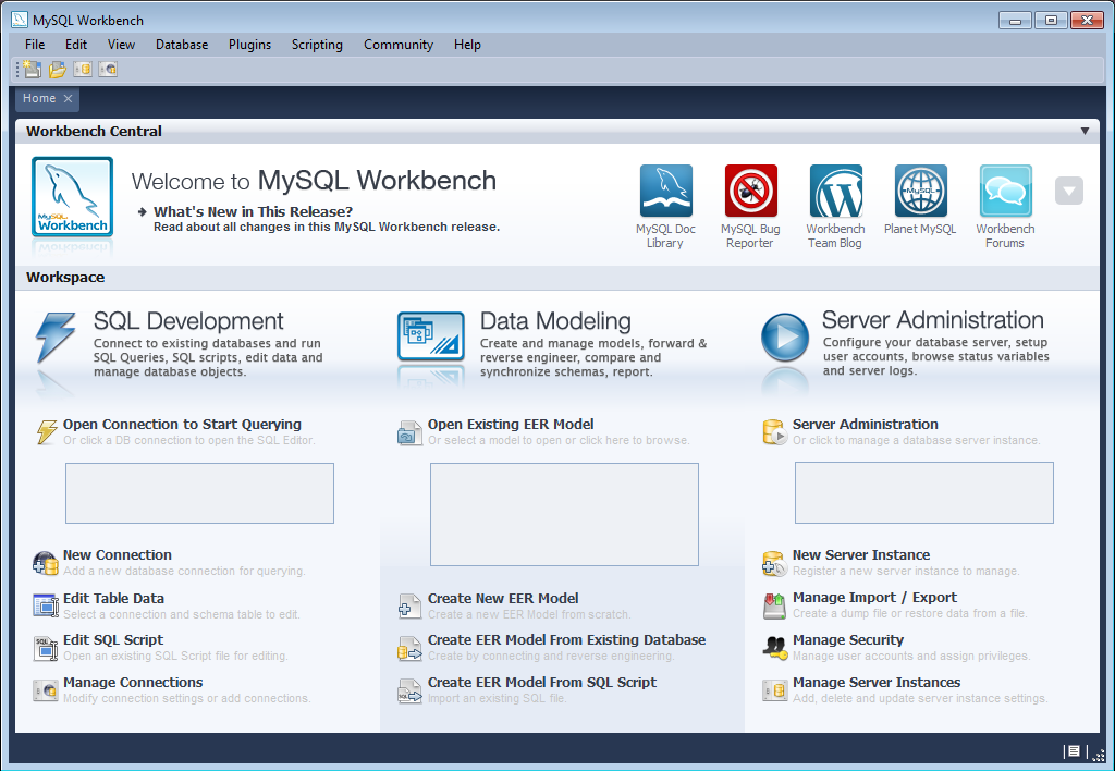
Launch MySQL Workbench. You will be presented with the Home screen:
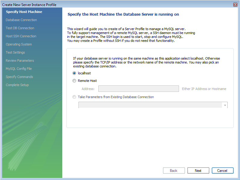
In order to administer your MySQL Server you need to first create a Server Instance. This contains information about the target server, including how to connect to it. From the Home screen of MySQL Workbench, click New Server Instance. The Create New Server Instance Profile wizard will be displayed.
In this tutorial we will connect to a locally installed server, so click .
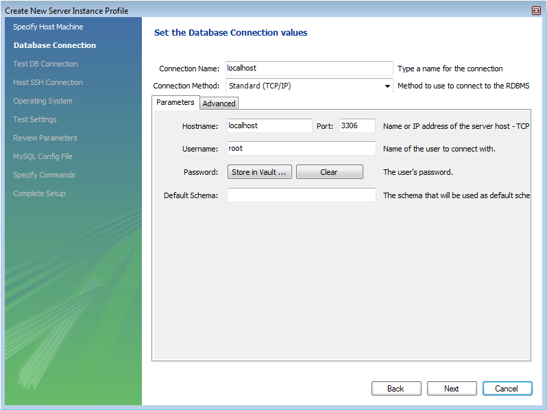
Next you will set up a connection, or select an existing connection to use to connect to the server. Assuming you have not already created a connection, you can use the default values here, although if your MySQL Server has a password set for root, you can set it here by clicking on Store in Vault. This allows you to connect to the server without needing to enter a password each time. It is also possible to use another account to connect to the server by setting the username and password here, if required.
You can now click .
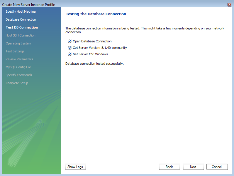
The connection will now be tested. You should see that the connection was successful. If not click and check that you have entered the information required.
If everything tested correctly, click .
On this screen you will set the operating system and installation type. In this case the installation is Microsoft Windows, and the installation type is MySQL 5.1 x86 Installer Package. Setting these options allows MySQL Workbench to determine location of configuration files, and the correct start up and shut down commands to use for the server.
Once you have set the operating system and installation type, click .
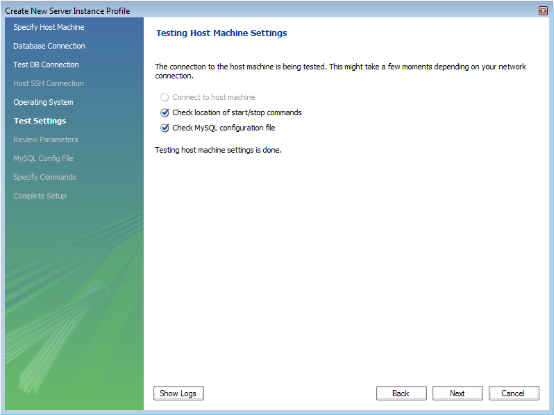
The wizard will now check that it is able to access the start up and shut down commands, and access the MySQL Server configuration file.
Check that everything is in order and then click .
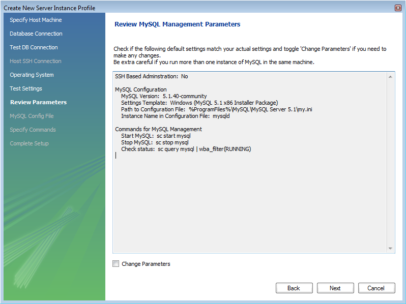
You now have a chance to review the configuration settings so far. The information displayed varies slightly depending on platform, connection method and installation type:
Click .
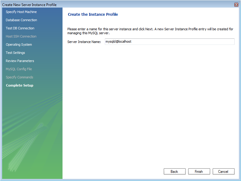
Finally you can give the server instance a suitable name. This will be used to select this particular instance from a list of available instances.
Having set the desired name, you can click to complete the server instance creation process.
You will now be returned to the Home screen. You will see the new server instance you created, along with the new connection you created as part of the above procedure.
You are now ready to test your new server instance.
From the Home screen, double-click the Server Instance you created. The Administrator will open on the Startup configuration page.
Click the button. The message window will show that the server has stopped.
Click the button to resume the server. The message window will confirm that the server is running.


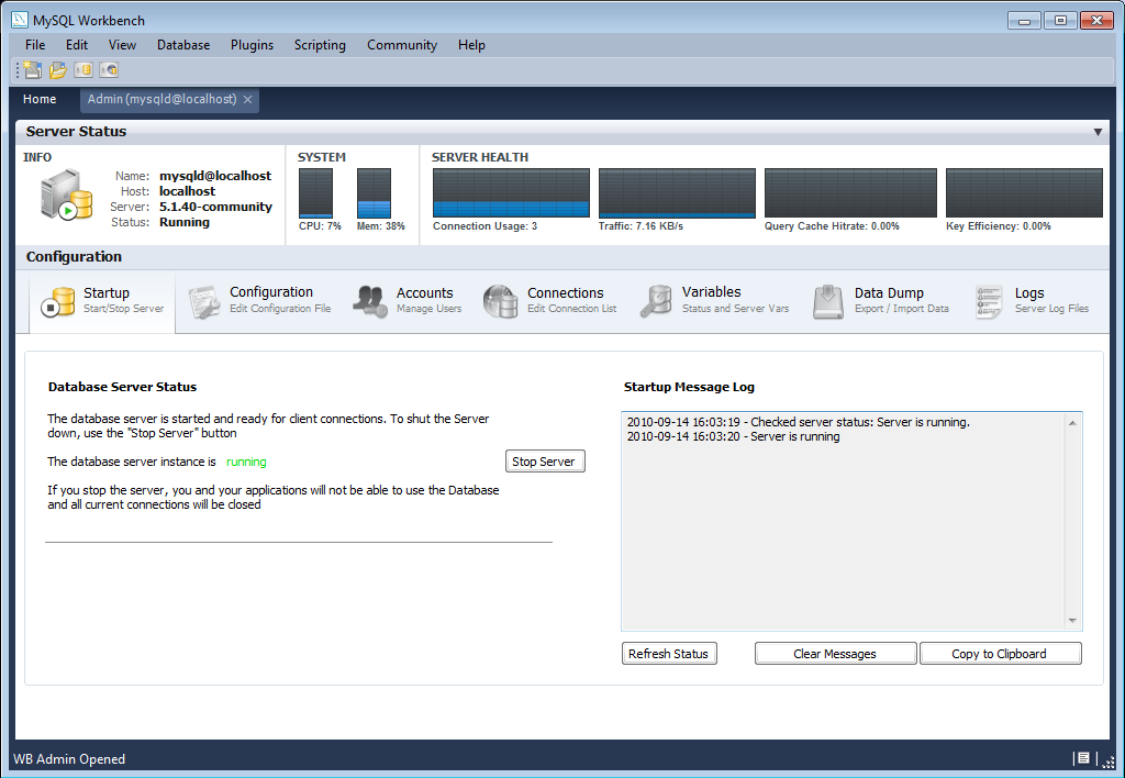
You have now seen how to create a server instance to allow you to manage a MySQL server.
For further information see Section 16.7, “Server Administration”.
In this section you will learn how to create a new database model, create a table, create an EER Diagram of your model, and then forward engineer your model to the live database server.
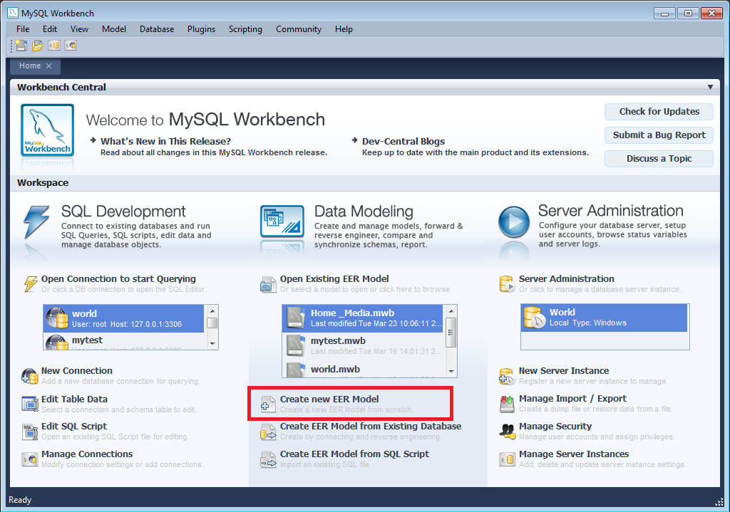
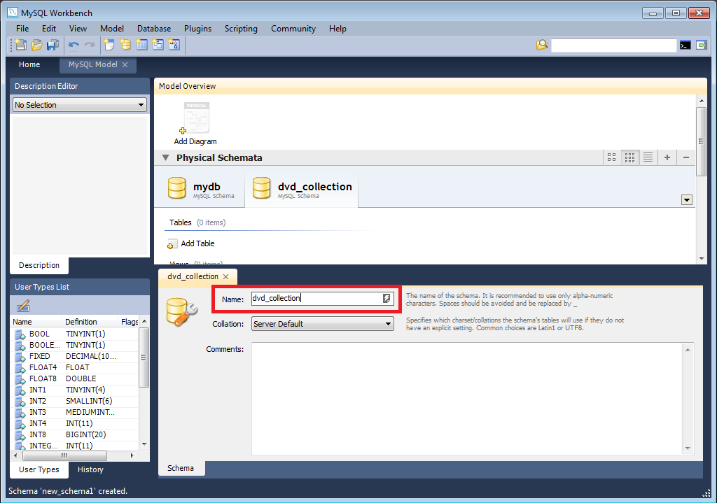
Start MySQL Workbench. On the Home screen select Create new EER Model. A model can contain multiple schemata. Note that when you create a new model, it contains the
mydbschema by default. You can change the name of this schema to serve your own purposes, or simply delete it.On the Physical Schemata toolbar, click the button to add a new schema. This will create a new schema and display a tabsheet for the schema. In the tabsheet, change the name of the schema to “dvd_collection”, by typing into the field called Name. Ensure that this change is reflected on the Physical Schemata tab. Now you are ready to add a table to your schema. If at this stage you receive a message dialog asking to rename all schema occurrences, you can click to apply your name change.
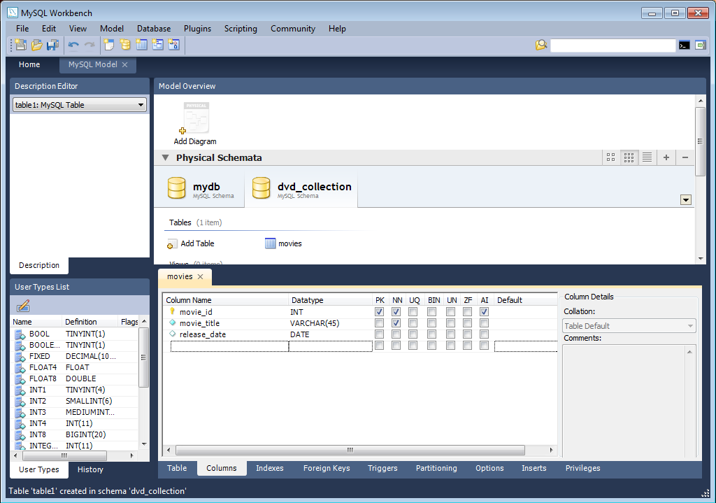
In the Physical Schemata section double-click Add Table.
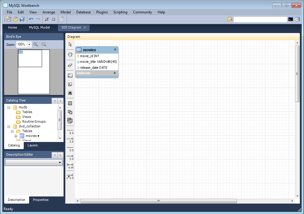
Double-click table1 to launch the table editor (you may not have to do this as the table editor will automatically load at this point if you are using later versions of MySQL Workbench). In the table editor, change the name of the table to “movies” and press Enter.The table editor will then switch from the Table tab to the Columns tab, to allow you to enter details of your table columns.
Change the name of the first column to “movie_id”. Select a data type of
INT. You will then make this column have the following properties: primary key, not null, autoincrement. To do this click the PK, NN, and AI checkboxes.Add two further columns:
Column Name Data Type Column Properties movie_title VARCHAR(45) NN release_date DATE (YYYY-MM-DD) None. Now you can obtain a visual representation of this schema so far. From the main menu select , . The EER Diagram will be created and displayed.
Now, in the table editor, change the name of the column “movie_title” to “title”. Note that the EER Diagram is automatically updated to reflect this change.
At this point you can save your model. Click the main toolbar button . In this case you have not yet saved this file so you will be prompted to enter a model file name. For this tutorial enter “Home_Media”. The Home_Media model may contain further schemata in addition to
dvd_collection, such ascd_collection. Click to save the model.You can synchronize your model with the live database server. First you need to tell MySQL Workbench how to connect to the live server. From the main menu select , .
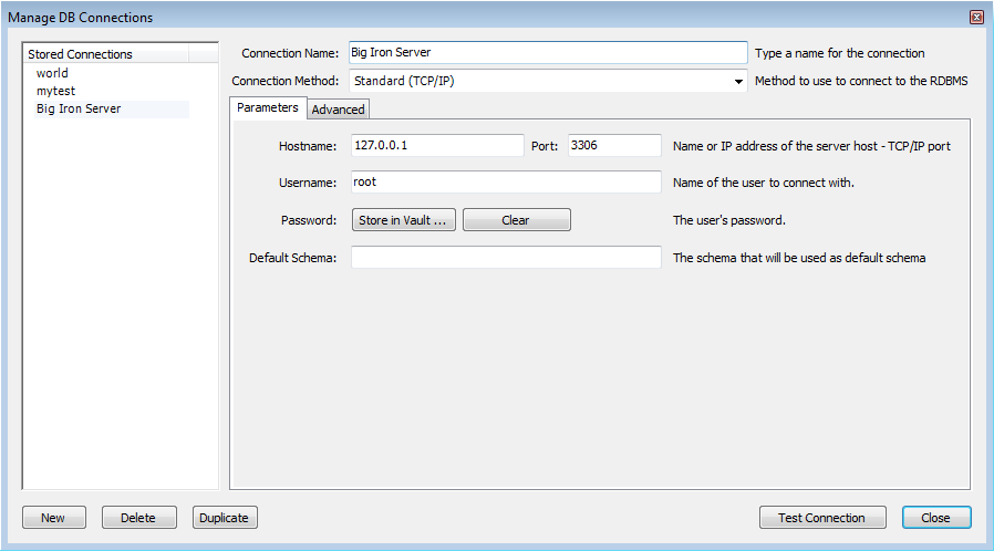
In the Manage DB Connections dialog click .
Enter “Big Iron Server” for the connection name. This allows us to identify which server this connection corresponds to, although it is possible to create multiple connections to the same server.
Enter the username for the account you will use to connect to the server.
Click on the button and enter the password for the username you entered in the previous step. You can optionally ignore this step, and you will be prompted for this password whenever MySQL Workbench connects to the server.
Click to test your connection parameters. If everything is OK at this point you can click .
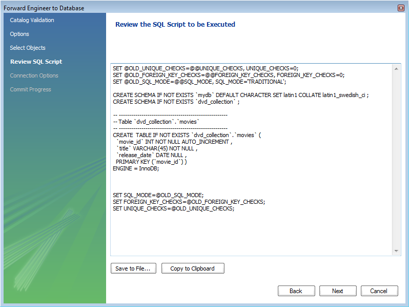
You are now ready to forward engineer your model to the live server. From the main menu select , . The Forward Engineer to Database wizard will be displayed.
The first page of the wizard is the Catalog Validation page. Click the button to validate the Catalog. If everything is in order the wizard will report that validaton finished successfully. Click Next to continue.
The Options page of the wizard shows various advanced options. For this tutorial you can ignore these and simply click Next.
On the next page you can select the object you want to export to the live server. In this case we only have a table, so no other objects need to be selected. Click .
The next screen, Review SQL Script, displays the script that will be run on the live server to create your schema. Review the script to make sure that you understand the operations that will be carried out. Click .
Select the connection you created earlier, “Big Iron Server”. Click . Check the messages for any erros, and then click to exit the wizard.
Ensure that the script ran without error on the server and then click . As a simple test that the script worked launch the MySQL Command Line Client. Enter
SHOW DATABASES;and identify your schema. EnterUSE dvd_collection;, to select your schema. Now enterSHOW TABLES;. EnterSELECT * FROM movies;, this will return the empty set as you have not yet entered any data into your database. Note that it is possible to use MySQL Workbench to carry out such checks, and you will see how to do this later, but the MySQL Command Line Client has been used here as you have probably used this previously.Ensure that your model is saved. Click Save Model to Current File on the main toolbar.
In the previous section you created a model, schema, and table. You also forward engineered your model to the live server. In this section you will see how you can use MySQL Workbench to add data into your database on the live server.
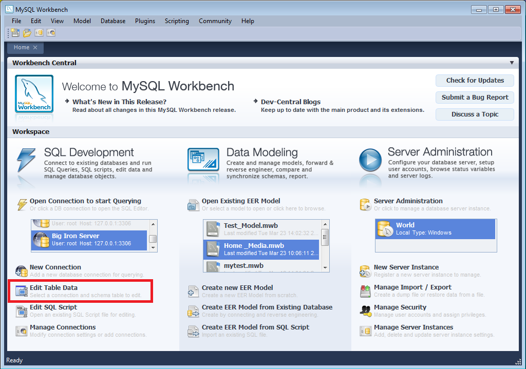
On the Home screen click the link Edit Table Data in the SQL Development area of the Workspace. This launches Edit Table Data wizard.
In the wizard select the “Big Iron Server” connection from the stored connection drop down listbox. Click .
Select the schema,
dvd_collection. Select the table to edit,movies. Click .You will see a data grid. This is where you can enter the data for your database. Remember that the
movie_idwas set to be autoincrement, so you do not need to enter values directly for this column. In the data grid enter the following movie information:title release_date Gone with the Wind 1939-04-17 The Hound of the Baskervilles 1939-03-31 The Matrix 1999-06-11 Above the Law 1988-04-08 Note: do not modify any values in the
movie_idcolumn.Now click the button in the toolbar located in the bottom right corner. A list of SQL statements will be displayed. Confirm that you understand the operations to be carried out. Click to apply these changes to the live server.
Confirm that the script was executed correctly and then click .
View the data grid again and observe that the autoincrement values have been generated.
Now you will check that the data really has been applied to the live server. Launch the MySQL Command Line Client. Enter
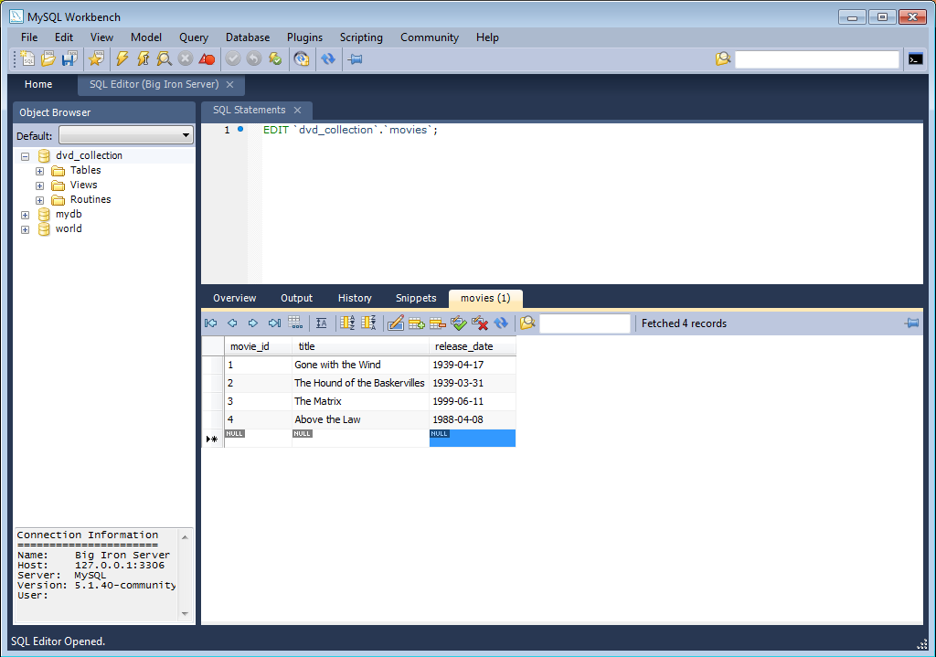
SELECT * FROM movies;to see the data just entered.You can also carry out a similar check from within MySQL Workbench. Click on the Home screen tab.
Click the link Open Connection to start Querying in the SQL Development section of the Workspace. This will launch the Connect to Database dialog. Select “Big Iron Server” from the drop down listbox. Click .
A new SQL Editor tab will be displayed. In the SQL Statements area enter the following code:
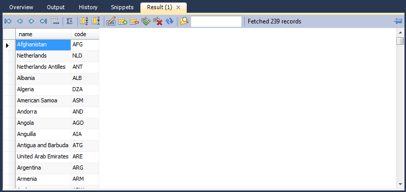
USE dvd_collection;
SELECT * FROM movies;
Now click the toolbar button. This resembles a small lightning bolt. The SQL Editor will display a new Result tab contain the result of executing the SQL statements.

In this section of the tutorial you have learnt how to add data to your database, and also how to execute SQL statements using MySQL Workbench.
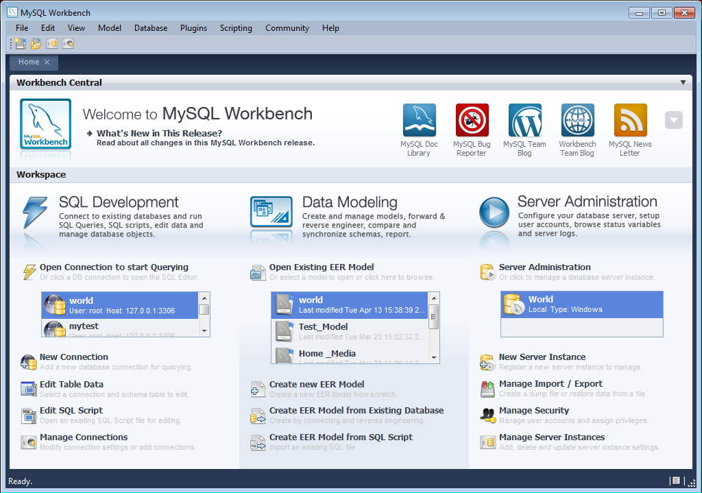
When MySQL Workbench is first started you will presented with the Home screen. There are two main sections of the Home screen:
Workbench Central
Workspace
MySQL Workbench 5.2 introduced the Home screen. MySQL Workbench 5.1 simply displays the MySQL Model workspace rather than the Home screen. Note that 5.1 does not support the SQL Editor and Server Administration functionality of 5.2.
These can be seen in the following screenshot:
Workbench Central enables you to keep up to date with MySQL Workbench news, events and resources. You can read the developer blogs, find out what's new in the release, access the forums, check for updates and file a bug report.
Workbench Central includes the following facilities:
What's new: A list of bug fixes and changes.
MySQL Doc Library: Built in documentation.
MySQL Bug Reporter: Links to the MySQL bug system, where you can report bugs.
MySQL Team Blog: Currently links to Workbench team blog.
Workbench Team Blog: Links to Workbench team blog.
MySQL Newsletter: Currently links to the MySQL Developer forum.
The Workspace is designed to allow you to quickly get to the task you would like to carry out. For convenience it is divided into three main areas, in alignment with MySQL Workbench functionality:
SQL Development
Data Modelling
Server Administration
For further information on SQL Development see Section 16.5, “SQL Development”.
For further information on Data Modeling see Section 16.6, “Data Modeling”.
For further information on Server Administration see Section 16.7, “Server Administration”.
From version 5.2.10, the MySQL Workbench application features a fixed minimum window size of 1024x768. You will not be able to manually reduce the size of the application to less than this resolution.
The menu sets MySQL Workbench defaults. Choosing the menu item opens the following dialog box:
The following list describes the dialog box tabs:
: The delete and undo history options
: Configuration for tools used by the Administrator functionality
: Configuration of the SQL Editor
: Default object names
:
: EER diagram settings
: Change colors and fonts used by various Workbench components
A more detailed discussion of these options follows.
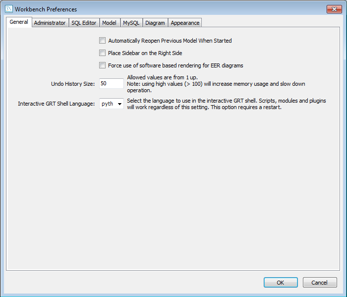
The General tab allows you to set the following options:
Automatically Reopen Previous Model When Started - check this if you want the model you previously worked on to be automatically reopened when you start MySQL Workbench.
Place Sidebar on the Right Side - by default the Sidebar is placed on the left-hand side of the MySQL Workbench application. Select this option to place it on the right-hand side.
Force use of software rendering for EER diagrams - MySQL Workbench will use OpenGL for rendering when available. However, due to faulty drivers, problems do occasionally occur. These issues can be resolved by selecting the software rendering option here.
Undo History Size - you can limit the size of the undo history here. Set this value to 0 to have an unlimited undo history.
Auto-save model interval - An open model that has not been saved will automatically be saved after this period. On loading a model file, MySQL Workbench will notify the user if the file was not previously saved correctly, due to a crash or power failure. MySQL Workbench can then attempt to recover the last auto-saved version. Note that for automatic recovery to be available for a new file, it will have to have been saved at least once by the user.
Interactive GRT Shell Language - you can select the language to be used in the GRT shell by chosing a language from the drop down listbox Interactive GRT Shell Language. Currently there is a choice between Lua and Python. Python is the recommended option.
This section provides configuration options that affect the Administrator functionality in MySQL Workbench.
Enables you to set paths to the mysqldump tool, and the mysql tool. If these are left blank the defaults will be used. This panel also enables you to set the directory for export dump files.
This section provides configuration options that affect the SQL Editor functionality in MySQL Workbench.
There are three main groups of parameters that can be set here:
SQL properties
Query Editor
Query Results
SQL Properties
SQL properties that can be set include the
SQL_MODE, case sensitivity of identifiers, and
the SQL delimiter used (by default this is $$).
The document property SqlMode defines
SQL_MODE for all operations affecting SQL
parsing at the document scope. The purpose of this option is to
preserve the consistency of SQL statements within the document.
The property has the following function:
Sets the
SQL_MODEDBMS session variable to the value stored in theSqlModeproperty of the document when performing reverse engineering, forward engineering or synchronization operations.Honors the
SQL_MODEvalues defined inSqlModeso that SQL parsing is correct.
Only a subset of all possible SQL_MODE values
affect the MySQL Workbench SQL parser. These values are:
ANSI_QUOTES,
HIGH_NOT_PRECEDENCE,
IGNORE_SPACE,
NO_BACKSLASH_ESCAPES,
PIPES_AS_CONCAT. Other values do not affect the
MySQL Workbench SQL parser and are ignored.
If the value of SqlMode is not set then the
default value of the SQL_MODE session variable
defined by the server stays unchanged during operations with the
server. However, the MySQL Workbench SQL parser will behave as if
SQL_MODE is also not set. This may potentially
lead to inconsistencies in SQL syntax stored in the document. If
you choose to not set the SqlMode property,
ensure that the default SQL_MODE variable
defined by the server does not contain any values from the
following list: ANSI_QUOTES,
HIGH_NOT_PRECEDENCE,
IGNORE_SPACE,
NO_BACKSLASH_ESCAPES,
PIPES_AS_CONCAT.
The SqlMode property is defined in two
locations: globally and at document scope. Every document upon its
creation copies the value of the global property into the property
defined for the document. The property value defined at document
scope always has higher priority over the one defined globally.
Query Editor
The query editor properties that can be set include the following:
Show Live Schema Overview - This option allows a simplification of the user interface by removing the Overview tab from the SQL Editor. This is also extremely useful if schemata have a large number of tables, or there is a large number of schemata in a model. In each of these cases load times would be greatly increased as the tables and schemata are enumerated and drawn.
Show Schema Contents in Schema Tree - enumerating, populating and drawing large numbers of items can significantly increase loading times. For this reason this facility can be switched off for models containing large numbers of schemata and tables.
Show Metadata Schemata - by default metadata schemata are not displayed. If required to view, for example to troubleshoot or check metadata information, they can be displayed by selecting this option.
Continue on SQL Script Error - should an error occur while executing a script, this option will allow you to continue executing the remainder of the script.
Forbid UPDATE and DELETE statements without a WHERE clause - this option enables the
SQL_SAFE_UPDATESoption for the sesson, preventingUPDATEandDELETEstatements from being executed if aWHEREclause is not present. This can avoid potentially dangerous situations where a command could accidentally update or delete all rows in a table.Max syntax error count - large complex scripts can contain many errors. Further, a syntax error early on can lead to many subsequent syntax errors. For these reasons it is possible to limit the number of errors displayed using this option, the default being 100 error messages.
Progress status update interval - When executing long running queries over a slow connection you would need to increase this value, to prevent excess load on the connection.
DBMS connection keep-alive interval - When executing long running queries over a slow connection you would need to increase this value to prevent the connection being lost.
Query Results
Limit Rows - queries can sometimes result in an excessive number of rows being returned as a result. This can heavily load the connection, and take time to display in MySQL Workbench. To prevent this you can set a more moderate value here.
Limit Rows Count - specify the maximum number of result rows to return.
Max. Field Value Length to Display - to avoid display problems due to excessive field length, it is possible to set the maximum field length to display (in bytes).
Treat BINARY/VARBINARY as non-binary character string - Binary byte string values are not displayed by default in the results grid, but are instead marked as BLOB values. These can then be viewed or edited with the BLOB editor. Non-binary character string values are displayed in the results grid, and can be edited in the grid cell or using the BLOB editor. Note that if this option is turned on, data truncation may result. This is because binary byte string values may contain null bytes as part of their valid data. For non-binary character strings a null byte terminates the string.
Enable Data Changes Commit Wizard - In the SQL Editor, when editing table data and then clicking the button, a wizard is launched to step you through applying you changes. This gives you a chance to review the SQL that will be applied to the live server to make the requested changes. If the option is deselected, then the changes will simply be applied to the server, without the wizard being displayed, and without a chance to review the changes that will be made.
This section provides configuration options that affect the Modeling functionality in MySQL Workbench.
Use the When Deleting Physical Model Figures in
Diagram frame to determine the behavior when deleting
objects from the EER diagram canvas. Choose Ask
and whenever you delete an object you will be asked whether you
wish to remove the object from an EER diagram only or also from
the catalog. The Keep Database Object in
Catalog is the safest option. You also have the option
of deleting the object from both the EER diagram and the catalog.
If you choose the Ask option a confirmation
dialog box will only open when you are deleting an object from
an EER Diagram. When deleting in the MySQL Model view there is
no confirmation dialog window
and the delete action always removes the object from the
catalog.
There are a variety of ways of deleting an object from an EER
canvas; using the eraser tool, choosing a
pop-up menu option, using the delete key, and by choosing the
delete option under the menu. In each
case, the action performed by the delete key is determined by the
option chosen from the When Deleting Physical Model
Figures in Diagram frame.
Use the model tab to set the default value for various object names and the primary key data type. A listing of those items with their default values follows:
Primary Key Column Name: id%table%
Primary Key Column Type: INT
Column Name: %table%col
Column Type: VARCHAR(45)
Foreign Key Name: fk%stable_%dtable%
Foreign Key Column Name: %table%_%column%
ON UPDATE: NO ACTION
ON DELETE: NO ACTION
Associative Table Name: %stable%_has_%dtable%
The Primary Key Column Name is the default
primary key column name when using the table editor. Likewise with
the default primary key data type, and column name and column
type. The remaining items are the default names used when using
the relationship tools on an EER diagram.
Items enclosed by percentage signs are variables. Their meanings are as follows:
%table%: The table associated with the object%column%: The column associated with the object%stable%: The source table%dtable%: The destination table
Legitimate values for the foreign key delete or update rules are:
RESTRICTCASCADESET NULLNO ACTION(default)
For more information about these actions see Section 16.6.7.1.3.5, “The Foreign Keys Tab”.
Use this tab to determine display settings for an EER diagram.
Select whether to expand new objects by checking the Expand New Objects check box and select whether to draw line crossings by checking the Draw Line Crossings check box.
From this tab you can also set the maximum number of characters for:
Column Names
Column Types
Routine Names
Note that this changes the display properties only, not the objects themselves.
Use this tab to set the available colors for the objects that appear on an EER diagram canvas. You can also add colors if you wish.
Changes made here affect the drop down list box of colors that appears on the toolbar when adding objects to an EER diagram canvas. For a discussion of using this list box see Section 16.6.5.2.1, “Tool-specific Toolbar Items”.
You can also use this tab to set the font face, font size, and the font style for the following list of items:
Editor
Layer Title
Text Figure Text
Text Figure Title
Connection Caption
Routine Group Figure Item
Routine Group Figure Title
Table Figure Items
Table Figure Section
Table Figure Title
View Figure Title
Choose from the drop down list of fonts, font sizes and styles.
Note that on Windows, the default font for the editor only
supports latin-1 characters. If you need to
use characters not supported by the latin-1
character set, you will need to change the font here.
This facility in MySQL Workbench provides the functionality that was formerly available in MySQL Query Browser.
MySQL Workbench now provides extensive facilities for working directly with SQL code. Before working directly with a live server a connection must be created. Once a connection is established it is the possible to execute SQL code directly on the server and manipulate the server using SQL code.
The starting point for embarking on SQL Development work is the SQL Development area of the Home screen, which has the following action items:
Open Connection to start Querying
Open Connection to start Querying (icon)
New Connection
Edit Table Data
Edit SQL Script
Manage Connections
Each of these action items is described in the following sections.
Clicking this action item launches the Connect to Database Wizard. From this wizard you can select a predefined connection. A new SQL Editor tab is launched where you
To read more about the SQL Editor, see Section 16.5.7, “SQL Editor”.
Open Connection to start Querying (icon)
If you already have created a connection to a database it will appear in this panel as an icon. Double-clicking the icon will directly launch a SQL Editor tab, and connect you to the database as defined by the connection.
To read more about the SQL Editor see Section 16.5.7, “SQL Editor”.
Clicking the New Connection action item launches the Manage DB Connections wizard. This wizard enables you to create a new connection. Note the wizard when launched from here does not display existing connections, it only enables you to create a new connection.
To read more about creating and managing connections see Section 16.5.6, “Manage DB Connections Dialog”.
This action item enables you to edit table data. When clicked the Edit Table Data wizard is launched. This is a two stage wizard. The first stage enables you to select a Stored Connection. The second stage enables you to select the Schema and Table you want to edit. Once the wizard is completed a SQL Editor tab is launched which displays a data grid that enables you to interactively edit table data as required.
To read more about the SQL Editor see Section 16.5.7, “SQL Editor”.
Clicking this action item launched the Edit SQL Script wizard. This is a two stage wizard. The first stage enables you to select a Stored Connection. The second stage enables you to select a SQL Script file, and optionally have the script executed after it is opened. Once the wizard is completed a SQL Editor tab will be launched, with the script displayed. If you optionally selected to run the script, the script will run and the results will be displayed.
Clicking this action item launches the Manage DB Connections wizard. This wizard also displays Stored Connections, which can be selected to change as required. New connections can also be created from this wizard.
To read more about managing connections see Section 16.5.6, “Manage DB Connections Dialog”.
MySQL Workbench provides a tool, the Manage DB Connections dialog, for creating and managing connections to servers. The connections created can then be used from the wizards that need to connect to a server, for example the wizard used to reverse engineer a live database. However, it is still possible to set connection parameters from these wizards if required, without invoking the Manage DB Connections dialog directly.
The Manage DB Connections dialog is invoked by selecting , from the main menu. It can also be invoked from any of the wizards requiring access to a live database. This is achieved by using the Manage Stored Connections item, found in the wizard's Stored Connection drop down list box.
Once the Manage DB Connections dialog is launched, you are presented with a dialog that enables you to create or delete connections:
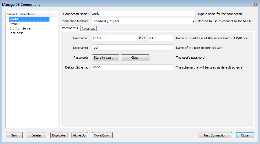
Click to create a new connection. Once created the connection can be selected from the Stored Connections list. You can then set various parameters for the connection, including the following:
Connection Name: The name to use to refer to this connection. This connection can then be selected from a dropdown listbox in other wizards requiring a connection.
Connection Method: The methods available are Standard TCP/IP, Local Socket/Pipe, and Standard TCP/IP over SSH.
Once you have selected a connection method, the textfields available in the Parameters tab and the Advanced tab of the dialog will change accordingly. More details of these options and paramaters are avalable in the following sections.
Once all parameters have been set as required you can click the button to test the connection to the live server. Once you are satisfied that the connection works as expected you can then close the wizard by clicking the button. You can then use the stored connection from any of the wizards requiring connection to a live server.
You can also duplicate an existing connection using the button.
This section discusses the settings on the Parameters and Advanced tabs for the Standard TCP/IP connection type.
Parameters tab
Hostname: The host name or IP address of the MySQL server.
Username: User account to use for the connection.
Password: Optional password for the account used. If you do not enter a password here you will be prompted to enter the password for the account to be used when MySQL Workbench attempts to establish the connection. MySQL Workbench also has the ability to store this password in a vault. On Linux, the vault is only implemented using the Gnome keyring facility - even on systems based on KDE.
Port: The TCP/IP port on which the MySQL server is listening (the default is 3306).
Default Schema: When the connection to the server is established this is the schema that will connected to by default. This becomes the default schema for use in other parts of MySQL Workbench.
Advanced tab
There are also more parameters that can be set for the connection using the Advanced tab:
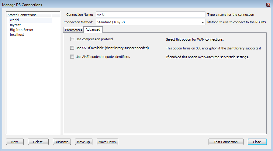
The advanced options include checkboxes for:
Use compression protocol: If checked, the communication between the application and the MySQL server will be compressed, which may increase transfer rates. This corresponds to starting a MySQL command-line tool with the
--compressoption.Use SSL if available: This option turns on SSL encryption. The client library needs to support this option. Note: this feature is currently not supported.
Use ANSI quotes to quote identifiers: Treat “"” as an identifier quote character (like the “`” quote character) and not as a string quote character. You can still use “`” to quote identifiers with this mode enabled. With this option enabled, you cannot use double quotation marks to quote literal strings, because it is interpreted as an identifier. Note: if this option is selected, it overrides the server setting.
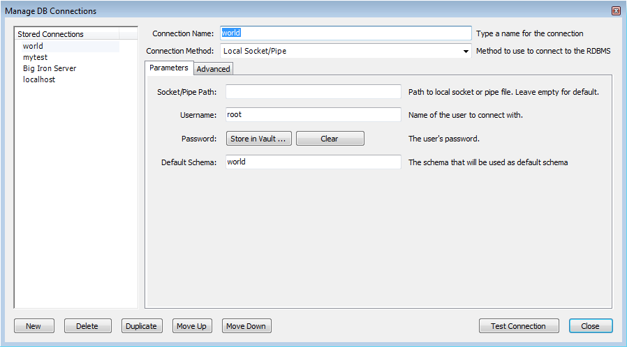
This connection type allows MySQL Workbench to connect to MySQL Server using a socket or pipe.
Parameters
The unique textfield here is Socket/Pipe
Path. The name of the socket or pipe is entered here.
If the textfield is left blank the default socket or pipe name is
used. The default pipe name on Microsoft Windows is
MySQL. On UNIX the default socket name is
/tmp/mysql.sock.
Ths option can be seen in the following screenshot:
Advanced
The only option available in this tab is Use ANSI quoutes to quote identifiers. This option was discussed in Section 16.5.6.1, “Standard TCP/IP Connection”.
The connection type allows MySQL Workbench to connection to MySQL Server using TCP/IP over an SSH tunnel.
Parameters
In addition to a number of parameters that are in common with Standard TCP/IP connections, this connection method features a number of specialized parameters. These are listed here:
SSH Hostname: This is the name of the SSH server. An optional port number can also be provided.
SSH Username: This is the name of the SSH username to connect with.
SSH Password: The SSH password. It is recommended that an SSH key file is also used.
SSH Key File: A path to the SSH key file. Note, only key files in OpenSSH format are currently supported.
These are shown in the following screenshot:

Advanced
The options here are the same as for the Standard TCP/IP connection, details of which can be found in Section 16.5.6.1, “Standard TCP/IP Connection”.
MySQL Workbench 5.2 introduced the SQL Editor facility. The SQL Editor
can be launched using various action items on the Home screen. It
can also be launched by selecting ,
from the main menu, or by using
the keyboard shortcut Ctrl+U on
Windows, or Cmd+U on Mac OS X.
At this point you will be asked to select either a stored
connection or enter the details for a new connection. Once a
connection has been made to the server a new tab called
SQL Editor
(schema) is displayed:

The main elements of the SQL Editor user interface are:
The Main Menu
Toolbar
SQL Query Panel
Main Tabsheets (Overview, Output, History, Snippets, Results)
Sidebar
Each of these are described in more detail in the following sections.
When a SQL Editor tab is selected the most important item on the main menu bar is . The Query item features the following menu items:
: Causes all statements in the SQL Query area to be executed, or only the statements selected.
: Causes the current SQL statement to be executed.
: Describes all statements, or the selected statement.
: Describes the current statement.
: Stop execution of the currently running script.
: Reconnect to the MySQL server.
: Creates a duplicate of the current SQL Editor tab.
: Commits a database transaction.
: Rolls back a database transaction.
: Synchronizes with the live server and refreshes views such as the live Overview tabsheet.
: Commits any changes you have made to the server.
: Discards any changes you have made.
: This enables you to export result sets to a file. Selecting this option displays the Export Query Results to File dialog. The dialog enables you to select which result set you wish to export, the file format (CSV, HTML, XML) and the name and location of the output file. Then click to export the data.
The toolbar features ten buttons, as shown in the following screenshot:
From left to right these are:
Create a New SQL Script File: Creates a new SQL Script tab where SQL code can be entered.
Open a SQL Script File: Cicking this button allows any saved SQL script to be loaded ready for execution. The script will be displayed in the SQL Query area.
Save SQL Script to File: Clicking this button allows the currently loaded SQL script to be saved to a file specified by the user.
Save SQL to Snippets List: SQL code snippets saved here can be given a name. They will appear in the SQL Snippets palette in the SQL Editor sidebar.
Execute SQL Script in Connected Server: Executes the currently loaded SQL script. Results are displayed in one or more Results tabs.
Execute Current SQL Statement in Connected Server: Executes the current SQL statement. Results are displayed in one or more Results tabs.
Explain (All or Selection): Explain SQL statements, or the currently selected one.
Stop the query being executed: Halts execution of the currently executing SQL script. This restarts the connection to the database server.
Toggle whether execution of SQL script should continue after failed statements: If the red 'breakpoint' circle is displayed the script will finish on a statement that fails. If the button is depressed so that the green arrow is displayed, then execution will continue past the failed code, possibly generating additional result sets. Any error generated from attempting to execute the faulty statement will be recorded in either case in the Output tabsheet.
Commit: Commits a transaction.
Rollback: Rolls back a transaction.
Toggle Auto-Commit Mode: If selected, transactions will automatically be committed.
Reconnect to DBMS: Re-establishes the database connection.
Refresh state of database structures: Refreshes the view of Schemata, Tables, Views and Routines that appears in the Live Overview Schema tabsheet. For example, if a SQL script creates a new table, it will not appear in the Overview tab until the refresh toolbar button is pressed.
Toggle whether query result tabs should be kept between queries by default: Normally when a script is executed any results generated from previous executions of the script are lost, and the new results displayed in the results tab. If this toggle button is pressed, so that the pin appears inserted, results will be retained between executions. Each execution of the script will create a new Results tab containing the result set.
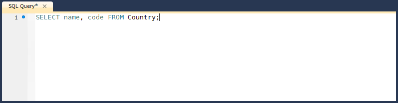
In this area you can enter SQL statements directly.
The statements entered can be saved to a file for later use. At any point you can also execute the statements you have entered.
To save a snippet of code entered into the SQL Query panel, click the , enter a name, and click . The snippet can be inserted into the SQL Query panel at any time by double-clicking the named snippet in the SQL Snippets Palette.
There is a quick way to enter the names of tables, views and columns. Simply double-click the item in the Schemata Palette and the name of the item clicked will be inserted into the SQL Query panel.
The main tabsheets area contains several tabs:
Live Schema Overview Tabsheet
Output Tabsheet
History Tabsheet
Results Tabsheets
Live Editing Tabsheet
Each of these is described in more detail in the following sections.
This tabsheet provides an overview of the schema. The schema objects Tables, Views and Routines are displayed for the current schema.
The Output tabsheet displays a summary of the communication between the script and the server. The messages displayed can be information or errors. Each message displays the time, the action that was carried out, and the response from the server. This is useful for troubleshooting scripts.
The History tabsheet provides a history of SQL operations carried out. Both the time of the SQL operation and the SQL code itself is recorded. To view the SQL executed, click the time, and the SQL code executed will be displayed in the SQL column.
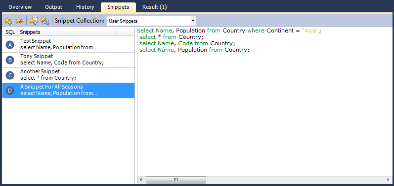
When you enter SQL code into the SQL Query area, you can use the Save SQL to Snippets List toolbar button to save your SQL code. At the time of saving you will be asked to specify a name. These named snippets can be viewed from the SQL Snippets Tab. You can load any SQL snippet into the SQL Query area by double-clicking the desired snippet in the Snippets Palette.
The results area of the screen shows the results from any queries that have been executed. If the script contains multiple queries then multiple result tabs will be generated, one for each query that returns results.
Controls are provided to allow you to easily move over the results. These are shown in the following screenshot:
There are a number of controls available. The controls from left to right are:
Move to first row: Highlights the first record in the current result set.
Move to previous row: Highlights the previous record.
Move to next row: Highlights the next record.
Move to last row: Highlights the last record in the current result set.
Toggle wrapping of cell contents: The data in the cell can either be truncated or wrapped. This button enables you to toggle between these options.
Sort Ascending: Sorts selected column in ascending order.
Sort Descending: Sorts column in descending order.
Export record set to an external file: Outputs record set to a CSV, HTML, or XML file as required.
Refresh Data from Data Source: Refreshes the current result set from the data source.
Search for substring within data: Search data for the string entered in the search box.
It is possible to edit data in real time using the Live Editing tabsheets. In the Overview tab, if a table is double-clicked, a live editing tab will be launched, allowing you to edit the data maintained in that table. Field data can be edited by clicking a field and entering the required data, or editing existing data. In addition to the controls offered by the Results tabsheet, the Live Editor tab features some additional controls. These controls are highlighted in the following screenshot:
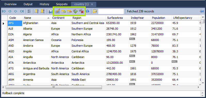
From left to right the highlighted controls are:
Edit current row: Enters edit mode for the currently selected record.
Insert new row: Inserts a new row and enables you to enter data. Your changes will not be reflected on the live server until you click .
Delete selected rows: Removes the selected rows. Your changes will not be reflected on the live server until you click .
Apply changes to data: Applies any changes that may have been made to the data fields to the live server.
Discard changes to data: Discards any changes that may have been made to the data fields, and does not apply them to the live server.
These additional controls allow you to apply or discard any changes you may have made to the field data. If changes are applied, the data will then be synchronized with the live server. If changes are discarded the live server will not be affected.
It is possible to enter a function, or other expression,
into a field. If doing so, the prefix
\func should be used, to prevent
MySQL Workbench from escaping quotation marks. For example, if
entering the expression md5('fred')
MySQL Workbench would generate the code
md5(\'fred\'). To prevent this enter the
expression as \func md5('fred'). This
will ensure that the quoting is not escaped.
See also Section 16.6.7.1.3.9, “The Inserts Tab”.
The Sidebar contains several panels. These are:
Connection Information Panel
Object Browser
Each of these is described in more detail in the following sections.
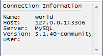
This section provides a summary of the current connection to the server.
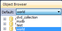
The Object Browser contains a drop down listbox and a schemata explorer control.
Default Schema Listbox
The drop down listbox lists the schema that are available on the currently connected server. It is possible to select a schema to become the currently active schema using this facility.
This selector executes a USE
statement. Once set,
subsequent statements without schema qualifiers will be
executed against this default schema. Note that this will only
be set for the query session. If you wish to set a default
schema for multiple MySQL Workbench sessions, you will need to set
the default schema for the stored connection. To do this from
the Home screen click Manage Connections,
then in the Manage DB Connection dialog
set the desired default schema on the
Parameters tab.
DB
Schemata Explorer
This area enables you to explore the schemata available on the currently connected server.
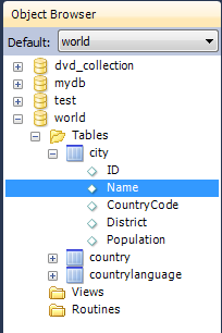
A useful feature that was introduced in MySQL Workbench 5.2.9 is the ability to rapidly enter the names of columns, tables and views into the SQL Statement area. Double-clicking views, tables, and column names in the schemata explorer will insert the corresponding name into the SQL Query area. This reduces typing significantly when entering SQL statements containing several tables, columns or views.
The Object Browser also features a context menu which can be displayed by right-clicking, for example, a table. Right-clicking a table would display the following menu items:
: Pulls up to 1000 records of table data from the live server into a Results tabsheet.
: Pulls table data from the live server into a named tabsheet, and allows editing. Data can be saved directly to the live server.
: There are various sub-menus:
Name (short): Copies the table name to the clipboard.
Name (long): Copies the table name to the clipboard in the form
`schema`.`table`.Column Names: Copies the column names to the clipboard in the form
`table`.`column1`, `table`.`column2`,....Select All Statement: Copies a SELECT all columns statement to the clipboard in the form:
SELECT
`table`.`column1`,
`table`.`column2`,
...
FROM `schema`.`table`;
Insert Statement: Copies an INSERT all columns statement to the clipboard.
Update Statement: Copies an UPDATE all columns statement to the clipboard.
Delete Statement: Copies a DELETE statement to the clipboard in the form
DELETE FROM
                    `world`.`country` WHERE
                    <where_condition>;
.
: Provides similar functionality to Copy to Clipboard. However, this options inserts the SQL code directly into the SQL Query panel, where it can be edited further as required.
: Displays the table editor loaded with the details of the table clicked on.
: Launches a dialog to allow you to create a new table.
: Drops a table. All data will be lost if this operation is carried out.
: Refreshes all schemata in the explorer by resynching with the server.
Right-clicking an empty area inside the object browser displays the following menu options:
: This enables you to create a new schema on the connected server. You can apply your changes to synchronize with the live server by clicking the button.
: Simply synchronizes with the live server so that information with the schemata explorer is updated.
- 16.6.1. Open an Existing EER Model
- 16.6.2. Create new EER Model
- 16.6.3. Create EER Model from Existing Database
- 16.6.4. Create EER Model from SQL Script
- 16.6.5. Model Editor
- 16.6.6. EER Diagram Editor
- 16.6.7. Working with Models
- 16.6.8. Modeling Tutorials
- 16.6.9. Printing
- 16.6.10. MySQL Workbench Schema Validation Plugins (Commercial Version)
- 16.6.11. Customizing DBDoc Model Reporting Templates
MySQL Workbench provides extensive capabilities for creating and manipulating database models. Some of these capabilities are listed here:
Create and manipulate a model graphically.
Reverse engineer a live database to a model.
Forward engineer a model to a script or live database.
Create and edit tables and insert data.
This is not an exhaustive list. These, and additional data modeling capablities, are discussed in the following sections.
The Home screen is the typical starting point for work with data modeling. In the Data Modeling section of the Workspace you can use the action items there to create and manage models, forward and reverse engineer, and compare and synchronize schemata. These action items are listed below:
Open an Existing EER Model
Open an Existing EER Model (icon)
Create new EER Model
Create EER Model from Existing Database
Create EER Model from SQL Script
These action items are described in the following sections.
Clicking this action item launches a file browser. You can then select the model file you wish to load. A new MySQL Model tab will then be created, and your model displayed.
Open an Existing EER Model (icon)
If you have already created one or more model files you can simply double-click the item of the model you wish to load. A new MySQL Model tab will be created, and your model displayed.
You can read more about modeling in the section Section 16.6.5, “Model Editor”.
Clicking this action item will launch a new MySQL Model tab, with a blank model ready for you to work on.
You can read more about modeling in the section Section 16.6.5, “Model Editor”.
The purpose of this action item is to allow you to create an EER Model from an existing live database. Clicking this action item launches the Reverse Engineer Database. This is a multi-stage wizard that enables you to select a connection to a live server, and select the schema and objects you wish to reverse engineer into your new model. This is a convenient way to see how an existing database is structured.
For further information on reverse engineering see Section 16.6.7.9.2, “Reverse Engineering a Live Database”.
The purpose of this action item is to allow you to create a model from a SQL Create script. Such a script may have been created by hand or may be as a result of reverse engineering an existing database to generate the script, which may then be modified according to requirements. Clicking this action item launches the Reverse Engineer SQL Script wizard. This is a multi-stage wizard that enables you to select the script you want to create your model from.
For further information see Section 16.6.7.9.1, “Reverse Engineering Using a Create Script”.
- 16.6.5.1. Modeling Menus
- 16.6.5.2. The Toolbar
- 16.6.5.3. EER Diagrams
- 16.6.5.4. The Physical Schemata
- 16.6.5.5. Schema Privileges
- 16.6.5.6. SQL Scripts and Model Notes
- 16.6.5.7. The History Palette
- 16.6.5.8. The Model Navigator Panel
- 16.6.5.9. The Catalog Tree Palette
- 16.6.5.10. The Layers Palette
- 16.6.5.11. The Properties Palette
When the Model Editor is executed from the Home Screen, the MySQL Model page is displayed. The MySQL Model page has three main panels: Description Editor, User Types List/History panel, and the main panel - the Model Overview panel. The Description Editor and User Types List/History panel are contained within the Sidebar. The Sidebar is located on the left by default, but can be relocated to the right using a setting in the Workbench Preferences dialog.
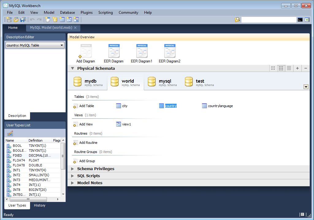
The sections within the Model Overview panel are:
EER Diagrams
Physical Schemata
Schema Privileges
SQL Scripts
Model Notes
For each of these sections objects can be added to a project by clicking the appropriate add object icon. You may also rename, edit, cut, copy, or delete objects on this page by right-clicking. Doing this opens a pop-up menu.
The sections within the MySQL Model page are discussed in the following sections.
Some menu options are not available in the OSS version of this application, and are only available in the Standard Edition. This is indicated where applicable.
Use this menu item to open a project, begin a new project, or save
a project. Choosing opens the default
schema, mydb. Choosing opens a file dialog box with the default file type
set to MySQL Workbench Models (MWB). To display a list of recently
opened MWB files, choose the menu
option. The keyboard command to create a new project is
Ctrl N and the command to open
an existing project is Ctrl O.
To close the currently active MySQL Model or
EER Diagram tab, use the option. You can also do this from the keyboard by
pressing Ctrl W. To reopen the
MySQL Model tab, see
Section 16.6.5.1.3, “The View Menu”. To reopen an EER
Diagram tab, double-click the EER
Diagram icon in the EER Diagrams
section of the MySQL Model page.
Use the or menu options to save a model. When you save a model
its name appears in the title bar of the application. If you have
made changes to a project and have not saved those changes, an
asterisk appears in the title bar following the model name. When
you save a model it is saved as a MySQL Workbench file with the
extension mwb.
Use the menu option to import a MySQL
data definition (DDL) script file, one created by issuing the
command mysqldump --no-data,
for example. If the script does not contain a CREATE
db_name; statement, the
schema objects will be copied to the default schema,
mydb. If the script creates a database, a new
tab bearing the database name is added to the Physical
Schemata section of the MySQL Model
page. If the script contains data, it will be ignored. Importing a
DDL script is discussed in detail in
Section 16.6.7.9.1, “Reverse Engineering Using a Create Script”.
Under the menu option you can also
import DBDesigner4 files.
There are variety of options under the menu item. You may generate the SQL statements necessary to create a new database or alter an existing one. These menu items are discussed in detail in Section 16.6.7.10.1, “Forward Engineering Using SQL Scripts”.
Using the menu item you can also export
an EER diagram as a PNG, SVG, PDF or Postscript file. For an
example of a PNG file see Figure 16.82, “The sakila EER Diagram”.
The menu item enables you to set the paper size, orientation and margins for printing purposes.
The print options are only enabled if the EER Diagrams tab is selected. You have the choice of printing your model directly to your printer, printing it as a PDF file, or creating a PostScript file. For more information see Section 16.6.9, “Printing”.
The printing options are only available in commercial versions of MySQL Workbench.
Use the menu option to set the following properties of your project:
Name: Defaults toMySQL ModelVersion: The project version number.Author: The project author.Project: The project name.Created: Not editable, determined by the MWB file attributes.Last Changed: Not editable, determined by the MWB file attributes.Description: A description of your project.
Under this menu item find the options for cutting, copying, and pasting. These actions can also be performed using the Ctrl X, Ctrl C, and Ctrl V key combinations. Undo a deletion using the option. The Ctrl Z key combination can also be used to undo an operation. It is also possible to carry out a operation using either the menu item, or the key combination Ctrl Y.
Also find a menu item for removing the currently selected object. The text description for this menu item changes to reflect the name of the currently selected object. The keyboard command for this action is Ctrl Delete. You can also right click an object and choose the delete option from the pop-up menu.
The menu item behaves differently depending upon circumstances. For instance, if an EER Diagram is active and a table on the canvas is the currently selected object, a dialog box may open asking whether you want to remove the table from the canvas only or from the database as well. For setting the default behavior when deleting from an EER Diagram see Section 16.4.4.4, “The Model Tab”.
If the MySQL Model page is active, the
selected object will be deleted from the catalog and there will
be no confirmation dialog box.
Choose to edit the currently selected object. You can also perform edits in a new window by selecting . The keyboard shortcut for is Ctrl E and Ctrl Shift E for .
The option has the following submenus:
(Keyboard shortcut, Ctrl A): Select all the objects on the active EER diagram.
(Objects of the same type): Use this option to find objects similar to the currently selected object.
: Use this option to find all the objects connected to the currently selected object.
These menu items are only active when an EER Diagram tab is selected. The and the menu options are disabled if no object is currently selected on an EER diagram.
When multiple objects have been selected using one of these menu options, you can navigate between selected items by choosing the or menu options.
Selecting items changes some of the menu options. If only one object is selected, that object's name appears after the , and menu options. If more than one object is selected, these menu items show the number of objects selected.
The menu item displays a sub-menu with the following menu items:
: Takes you to the toolbar search box. You can look for objects in the current view. Find can locate objects in the Model view, the EER Diagram view, and also in the Catalog palette.
: Finds the next occurrence of the object.
: Finds the previous occurrence of the object.
: Displays the Search and Replace dialog. This is currently only for use with the SQL Editor, to allow you to quickly search and replace script code items.
The Standard Edition of MySQL Workbench includes a more advanced Find facility:
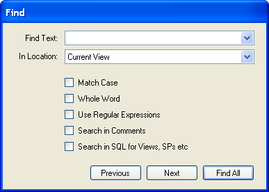
You can search the following locations:
Entire Model: Search the entire model.
Current View: Search the current view only. This may be the
MySQL Modelpage.All Views: Search the
MySQL Model Pageand all EER diagrams.Database Objects: Search database objects only.
Selected Figures: Search the currently selected objects. This feature only works for EER diagrams.
Enter the text you wish to search for in the Find Text drop down list box. You may also select any or all of the following check boxes:
Match Case
Whole Word
Use Regular Expression
Search in Comments
Search in SQL for Views, SPs etc.
Any text you enter into the Find Text drop down list box is retained for the duration of your session. Use the or buttons to find occurrences of your search criterion.
Clicking the button opens a Find Results window anchored at the bottom of the application. If you wish, you may undock this window as you would any other.
Use this window to navigate to objects. For example, double
clicking the Description of an object located
on an EER diagram navigates to the specific diagram and selects
the object. Notice that the properties of the object are
displayed in the Properties palette.
The Find dialog window can also be opened
using the Ctrl F key
combination. Use Ctrl G to
find the next occurrence and Ctrl
Shift G to find a previous
occurrence. Close the Find dialog window by
clicking the in the top right corner or
by pressing the Esc key.
This menu option enables you to set global preferences for the MySQL Workbench application.
For further information see Section 16.4.4, “Workbench Preferences”.
The Options available under this menu item are:
: Selects the Home screen.
: Open the
Model Navigatorpalette: Open the
Catalogpalette: Open the
Layerspalette: Open the
User Datatypespalette: Open the
Descriptionpalette: Open the
Propertiespalette: Open the
Historypalette
These menu options provide a means for opening the windows associated with these options.
: Use this option to display the console output. The keyboard shortcut for this menu item is Ctrl F2.
: Open the GRT shell. For more information about the GRT shell see Section 16.8.5, “The Workbench Scripting Shell”. The keyboard shortcut for opening the GRT shell is Ctrl F3.
: Reset all windows to their default layout.
: The default level of detail of an EER diagram.
: Zoom in on an EER diagram.
: Zoom out from an EER diagram.
The ability to zoom in on an EER diagram is also available using the slider tool in the
Model Navigatorpalette. See Section 16.6.5.8, “The Model Navigator Panel”.: Use this option to bookmark an object. From the keyboard select the object you wish to bookmark and use the key combination Ctrl Shift and the number of the marker (1 through 9). You may create up to nine markers.
: Return to a marker. From the keyboard use the Ctrl key and the number of the marker.
The Arrange menu option applies only to objects
on an EER diagram canvas and is only visible if an EER diagram
view is active. The options under this menu item are as follows:
: Align items on the canvas to the grid lines.
: Use this option to bring objects to the foreground.
: Use this option to move objects to the background.
: Use this option to center objects on the canvas.
: Use this option to automatically arrange objects on the canvas.
: This option expands an object on an EER diagram. For example, if a table has a long column name that is not fully displayed, using this menu option will expand the table making the column visible. This menu item is not enabled until an object is selected.
: Use this option to expand all objects on an EER diagram. This option will display a table's columns if the object notation supports expansion. Some object notations, such as
Classic, do not allow for expansion or contraction. Indexes will not automatically be expanded unless they were previously expanded and have been collapsed using the menu option.: Undo the operation performed by .
The menu options available under the Model menu
item are as follows:
Add Diagram: Create a new EER Diagram. The keyboard shortcut is Ctrl T.
Create Diagram From Catalog Objects: Create an EER diagram from all the objects in the catalog.
DBDoc – Model Reporting...: For information on using this menu option see Section 16.6.5.1.5.1, “The DBDoc Model Reporting Dialog Window (Commercial Version)”. Commercial version only.
User Defined Types: Choosing this menu option presents you with a dialog box, allowing you to add and delete user defined data types.
Object Notation: The items available under this option are discussed in Section 16.6.5.1.5.3, “The Object Notation Menu Options”.
Relationship Notation: The items available under this option are discussed in Section 16.6.5.1.5.4, “The Relationship Notation Menu Option”.
Diagram Properties and Size: Choosing this menu option opens a diagram size dialog box. Use this dialog box to adjust the width or height of the canvas. The unit of measure is pages; the default value is two.
When you have tables with numerous columns, use this menu option to increase the size of the EER.
Validation: The items available under this option are discussed in Section 16.6.5.1.5.2, “The Validation Menu Options (Commercial Version)”. Commercial version only.
Model Options: Set options at the model level. These options should not be confused with the options that are set globally for the Workbench application, and which are now referred to as Workbench Preferences. The available model options are a subset of the Workbench Preferences options.
For more information on Workbench Preferences see Section 16.4.4.4, “The Model Tab”.
This dialog window is found by navigating to the menu item and choosing the option.
The option is not available in the MySQL Workbench OSS version.
Use this dialog window to set the options for creating documentation of your database models.
You can about this menu item in more detail in the following section The DBDoc Model Reporting Dialog Window.
Under the menu option there are two validation options, and . Use these options for general validation and MySQL-specific validation of the objects and relationships defined in your model.
These options are not available in the MySQL Workbench OSS version.
Under the option the menu items are:
: Perform all the validation options available
: Check for objects with no content, for example a table with no columns
: Check the efficiency of tables, for example a table with no primary key defined
: Check for duplicate identifiers, for example two tables with the same name
: Check for consistent naming conventions
: Check, for example, that a foreign key does not reference a nonprimary key column in the source table
Under the option the menu items are:
: Perform all the validation options available
: Check for invalid references, for example, a table name longer than the maximum allowed
: Check for correct SQL syntax
: Check for objects with the same name
For detailed information about validation see Section 16.6.10, “MySQL Workbench Schema Validation Plugins (Commercial Version)”.
The options under the menu apply exclusively to an EER diagram. They are grayed out if an EER diagram tab is not selected.
The menu options are as follows:
: Display table columns, indexes, and triggers.
: Show only a table's columns.
: Show only columns that are primary and foreign keys.
: Similar to the
Workbench (Simplified)style showing only the table's columns.: The ICAM DEFinition language information modeling style.
The object notation style that you choose persists for the duration of your MySQL Workbench session and is saved along with your model. When MySQL Workbench is restarted, the object notation reverts to the default.
If you plan to export or print an EER diagram be sure to decide on a notation style first. Changing notation styles after objects have been placed on a diagram can significantly change the appearance of the diagram.
The options under the menu apply exclusively to an EER diagram. They are grayed out if an EER diagram tab is not selected. The menu options are as follows:
: The default modeling style. For an example see Figure 16.79, “Adding Tables to the Canvas”.
: Uses a diamond shape to indicate cardinality.
: Universal Modeling Language style.
: The ICAM DEFinition language information modeling method
To view the different styles, set up a relationship between two or more tables and choose the different menu options
The relationship notation style that you choose persists for the
duration of your MySQL Workbench session and is saved along with
your model. When MySQL Workbench is restarted, the relationship
notation reverts to the default, the Crow's
Foot style.
If you plan to export or print an EER diagram be sure to decide on a notation style first. Changing notation styles after objects have been placed on a diagram can significantly change the appearance of the diagram.
There are several options under the menu option:
: Launche the SQL Editor, which enables you to create SQL code and execute it on a live server. For more information see Section 16.5.7, “SQL Editor”.
: Launche the Manage DB Connections dialog, which enables you to create and manage multiple connections. For more information see Section 16.5.6, “Manage DB Connections Dialog”
: Create a model from an existing database. For more information, see Section 16.6.7.9.2, “Reverse Engineering a Live Database”.
: Create a database from a model. For more information, see Section 16.6.7.10.2, “Forward Engineering to a Live Server”.
: Synchronize your database model with an existing database. For more information, see Section 16.6.7.10.3, “Database Synchronization”.
: Compare your schema model with a live database or a script file. Section 16.6.7.10.4, “Creating a Catalog Diff Report”.
The menu option lists any plugins that you may have installed. For more information about this menu option see Section 16.8.3, “Plugins”.
This menu currently has three items:
: Launches the MySQL Workbench Scripting Shell.
: Executes the specified script.
: Enables you to load and install a plugin/module file.
The menu option offers the following choices:
Use these menu options to go online and learn more about MySQL Workbench.
The menu option offers the following choices:
: Open a window showing the MySQL Workbench documentation. Read, search, or print the documentation from this window.
: Open your default browser on the MySQL Workbench website and check for a newer version.
: Update to the latest version.
: Open your default browser on the MySQL website home page.
: Open your default browser on the MySQL Workbench product page.
: Information about your system, useful when reporting a bug. For more information, see Section 16.6.5.1.10.1, “System Info”.
: Open your default browser on the MySQL bug report page.
: Open your default browser to see a list of current bugs.
: Show the MySQL Workbench
Aboutwindow.
Use these menu options to go online and learn more about MySQL Workbench.
Use the menu option to determine information about your system. This option is especially useful for determining your rendering mode. Sample output follows.
read_mysql_cfg_file C:\Program Files\MySQL\MySQL Server 5.1\my.ini
[('tmp_table_size', '9M'),
('myisam_sort_buffer_size', '18M'),
('table_cache', '256'),
('read_rnd_buffer_size', '256K'),
('port', '3306'), ('max_connections', '100'),
('innodb_buffer_pool_size', '18M'),
('myisam_max_sort_file_size', '100G'),
('sql-mode', '"STRICT_TRANS_TABLES,NO_AUTO_CREATE_USER,NO_ENGINE_SUBSTITUTION"'),
('basedir', '"C:/Program Files/MySQL/MySQL Server 5.1/"'),
('default-character-set', 'latin1'),
('datadir', '"C:/ProgramData/MySQL/MySQL Server 5.1/Data/"'),
('innodb_log_buffer_size', '1M'),
('innodb_log_file_size', '10M'),
('innodb_thread_concurrency', '8'),
('read_buffer_size', '64K'),
('innodb_additional_mem_pool_size', '2M'),
('thread_cache_size', '8'),
('innodb_flush_log_at_trx_commit', '1'),
('query_cache_size', '0'),
('sort_buffer_size', '256K'),
('default-storage-engine', 'INNODB'),
('key_buffer_size', '11M')]
MySQL Workbench OSS for Windows version 5.2.8
Cairo Version: 1.8.6
Rendering Mode: GDI requested (create a diagram to confirm)
OpenGL Driver Version: Not Detected
OS: unknown
CPU: Intel(R) Core(TM)2 Duo CPU T9300 @ 2.50GHz, 1.0 GB RAM
Video adapter info:
Adapter type: VirtualBox Graphics Adapter
Chip Type: VBOX
BIOS String: Version 0xB0C2 or later
Video Memory: 12288 KBThe MySQL Workbench toolbar is found immediately below the menu bar. The following tools always appear on the toolbar:
The new document icon: Click this icon to create a new document
The folder icon: Click this icon to open a MySQL Workbench file (MWB)
The save icon: Click this icon to save the current MySQL Workbench project
The right and left arrows: Click the left arrow to perform an “Undo” operation. Click the right arrow to perform a “Redo” operation.
Other tools appear on the toolbar depending upon the context.
When an EER diagram canvas is selected, the following icons appear to the right of the arrow icons:
The toggle grid icon: Used for turning the grid on and off
The grid icon: Used for aligning objects on the canvas with the grid
The toolbar also changes depending upon which tool from the vertical toolbar is active. These tools are discussed in Section 16.6.6.1, “The Vertical Toolbar”.
If the Table tool is active, drop down list
boxes of schemata, engine types and collations appear on the
toolbar. The table properties can then be modified using the
Properties Editor.
When an object is selected the object's properties, such as color, can be changed in the Properties Editor.
Use the Add Diagram icon in this area to create
EER diagrams. When you add an EER diagram a new tab appears below
the toolbar. Use this tab to navigate to the newly created EER
diagram. EER Diagrams are discussed in depth in
Section 16.6.6, “EER Diagram Editor”.
The Physical Schemata panel of the
MySQL Model page shows the active schemata and
the objects that they contain.
Expand and contract the Physical Schemata
section by double-clicking the arrow on the left of the
Physical Schemata title bar. When the
Physical Schemata section is expanded, all the
schemata that are currently loaded are displayed.
Each schema shows as a tab; a specific schema is selected by
clicking its tab. When MySQL Workbench is first opened a default
schema, mydb is selected. You can start working
with this schema or you can load a new MySQL Workbench Models
(MWB) file.
There are a variety of ways to add schema to the Physical
Schemata panel. You can open an MWB file, reverse
engineer a MySQL create script, or, if you are using a commercial
version of MySQL Workbench, you can reverse engineer a database by
connecting to a MySQL server.
You can also add a new schema by clicking the
button on the top right of the
Physical Schemata panel. To remove a schema,
click its tab and use the button found to
the immediate left of the button. To the
left of these buttons are three buttons that control the way
database object icons are displayed. The left-most button displays
database objects as large icons, the next button to the right
displays small icons in multiple rows, and the last button
displays small icons in a single list.
The Physical Schemata panel is divided up
into the following sections:
Tables
Views
Routines
Routine Groups
Each section contains the specified database objects and an icon used for creating additional objects.
Any database objects added to an EER diagram canvas also show up
in the Physical Schemata section. For
information about adding objects to an EER diagram canvas see
Section 16.6.6, “EER Diagram Editor”.
The Privileges panel of the MySQL
Model page is used to create users for your schemata and
also to define roles —.
The Schema Privileges panel is divided up into
the following sections:
Users
Roles
The following image displays the Schema
Privileges section of the MySQL Model
tab.
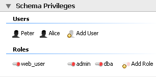
To add a role, double-click the Add Role
icon. Doing this creates a role with the default name
role1. Right-clicking a role opens a pop-up
menu with the following options:
': Cut the role
': Copy the role
: Open the role editor.
: Open the role editor in a new editor window.
': Remove the role
: Currently not implemented.
To rename a role, simply click the role name and you will then be able to edit the text.
All roles that have been defined are listed under
Roles on the left side of the role editor.
Double-clicking a role object opens the role editor docked at
the bottom of the screen.
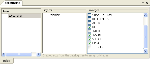
Select the role that you wish to add objects to. You may drag
and drop objects from the Physical Schemata
to the Objects section of the role editor. To
assign privileges to a role select a role from the
Roles section and then select an object in
the Objects section. In the
Privileges section check the rights you wish
to assign to this role. For example, a
web_user role might have only
SELECT privileges and only for database
objects exposed through a web interface. Creating roles can make
the process of assigning rights to new users much easier.
To add a user double-click the Add User icon.
Doing this creates a user with the default name
user1. Double-clicking this user opens the
user editor docked at the bottom of the application.
In the User Editor, set the user's name using
the Name text box and set the password
using the Password text box. Assign one
role or a number of roles to the user by selecting the desired
roles from the text area on the right and then clicking the
button. Roles may be revoked by
moving them in the opposite direction.
Right-clicking a user opens a pop-up menu. These options function as described in Section 16.6.5.5.1, “Adding Roles”.
The two remaining panels on the MySQL Model
page are SQL Scripts panel and the
Model Notes panel.
Use the SQL Scripts panel to load and modify
SQL scripts. If you created your project from an SQL script and
plan to create an ALTER script, you may want to
add the original script here, since it will be needed to create an
ALTER script. For more information, see
Section 16.6.7.10.1.2, “Altering a Schema”.
Use the Model Notes panel to write project
notes. Any scripts or notes added will be saved with your project.
Use the History palette to review the actions
that you have taken. Left-clicking an entry opens a pop-up menu
with the option, . Choose this option to select a single entry.
You can select multiple contiguous entries by pressing the
Shift key and clicking the entries you wish to
copy. Select noncontiguous entries by using the
Ctrl key.
Only actions that alter the MySQL model or change an EER diagram
are captured by the History palette.
Docked at the top left of the application is the Model Navigator, or Bird's Eye panel. This panel gives you an overview of the objects placed on an EER diagram canvas and for this reason it is most useful when an EER diagram is active. Any objects that you have placed on the canvas should be visible in the navigator.
The Model Navigator shows the total area of an EER diagram. A black rectangular outline indicates the view port onto the visible area of the canvas. To change the view port of an EER diagram left click this black outline and drag it to the desired location. You can zoom in on selected areas of an EER diagram by using the slider tool at the bottom of this window. The dimensions of the view port change as you zoom in and out. If the slider tool has the focus you can also zoom using the arrow keys.
The default size of the Model Navigator is two
pages. To change this use the ,
menu option.

The Catalog Tree palette shows all the schemata
that are present in the Physical Schemata
section of the MySQL Model page. Expand the
view of the objects contained in a specific schema by clicking the
button to the left of the schema name.
Doing this displays the following folder icons:
Tables
Views
Routine Groups
Expand each of these in turn by clicking the button to the left of the folder icon.
Selecting an object in this palette, displays its properties in
the Properties palette, which can be found in
the lower left corner of the screen.
The Catalog Tree palette is primarily used to drag and drop objects onto an EER diagram canvas.
On Linux, there is a quirk in the GTK tree control, where a simple click always generates a new selection. If you want to drag multiple objects from the Catalog Tree to the EER diagram canvas, you need to perform the operation as follows:
Click first item in tree.
Hold shift and click last item and do not release the shift key.
Keep the shift key depressed and commence the dragging operation.
Release the shift key before you release the mouse button to successfully drop selected objects onto the canvas.
This also applies to use of the Ctrl key when selecting multiple non-adjacent elements in the Catalog Tree.
You can toggle the sidebar on and off using the Toggle Sidebar button, which is located in the top right of the application.
This palette shows all the layers and figures that have been
placed on an EER diagram. If a layer or figure is currently
selected, an X appears beside the name of the
object and its properties are displayed in the
Properties palette. This can be especially
useful in determining which objects are selected when you have
selected multiple objects using the various options under the
menu option. For more information on
this topic see Section 16.6.5.1.2, “The Edit Menu”.
Selecting an object in the Layers palette also
adjusts the view port to the area of the canvas where the object
is located.
In some circumstances you may want to make an object on an EER
diagram invisible. To do this, select the object and, in the
Properties palette, set the
visible property to False.
The Layer palette provides an easy way to
locate an object, such as a relationship, that has been set to
hidden. Open the Layers
palette and select the object by double-clicking it. You can
then edit the object and change its visibility setting to
Fully Visible.
The Properties palette is used to display and
edit the properties of objects on an EER diagram. It is especially
useful for editing display objects such as layers and notes.
All objects except connections have the following properties except as noted:
color: The color accent of the object. The color of the object is displayed here as is its hexadecimal value. Change the color of the object by changing this value. Only characters that are legal for hexadecimal values may be entered. You can also change the color by clicking the button. This opens a color changer dialog box.description: Applicable to layers only. A means of documenting the purpose of a layer.expanded: This attribute applies to objects such as tables that can be expanded to show columns, indexes, and triggers.height: The height of the object. Depending upon the object, this property may be read only or read/write.left: The number of pixels from the object to the left side of the canvas.locked: Whether the object is locked or not. The value for this attribute is eithertrueorfalse.manualSizing: Whether the object has been manually sized or not. The value for this attribute is eithertrueorfalse.name: The name of the object.top: The number of pixels from the object to the top of the canvas.visible: This property controls whether an object shows up on the canvas or not. Use‘1’for true and‘0’for false. It is currently only used for relationships.width: The width of the object. Depending upon the object, this property may be read only or read/write.
In addition to the properties listed above, tables also have the following properties:
indexesExpanded: This property determines whether indexes are displayed when a table is placed on the canvas. Use‘1’for true and‘0’for false.triggersExpanded: This property determines whether triggers are displayed when a table is placed on the canvas. Use‘1’for true and‘0’for false.
For a discussion of the properties of connections see Section 16.6.7.2.3, “The Properties of a Connection”.
EER diagrams are created by double-clicking the Add
Diagram icon. You may create any number of EER diagrams
just as you may create any number of physical schemata. Each EER
diagram shows as a tab below the toolbar; a specific EER diagram is
selected by clicking its tab.
Clicking an EER diagram tab navigates to the canvas used for
graphically manipulating database objects. On the left side of this
page is the Vertical Toolbar.
The vertical toolbar shows on the left sidebar when an EER diagram tab is selected. The tools on this toolbar assist in creating EER diagrams.
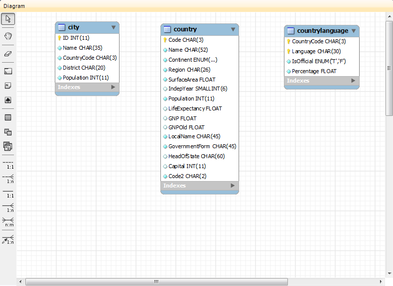
Clicking a tool changes the mouse pointer to a pointer that resembles the tool icon, indicating which tool is active. These tools can also be activated from the keyboard by pressing the key associated with the tool. Locating the mouse over a toolbar icon displays a description of the tool and its shortcut key.
A more detailed description of each of these tools follows.
The standard mouse pointer, located at the top of the vertical toolbar, is the default mouse pointer for your operating system. Use this tool to revert to the standard mouse pointer after using other tools.
From the keyboard, use the Esc key to revert to the default pointer.
The hand tool is used to move the entire EER diagram. Left-click on this tool and then left-click anywhere on the EER diagram canvas holding down the mouse button. Moving the mouse changes the view port of the canvas.
To determine your position on the canvas look at the
Model Navigator panel on the upper right. If
the Model Navigator panel is not open, use
the , ,
to open it.
From the keyboard, use the H key to activate this tool.
You can also change the view port of an EER diagram using the
Model Navigator panel. To do this see
Section 16.6.5.8, “The Model Navigator Panel”.
Use the eraser tool to delete objects from the EER Diagram canvas.
Change the mouse pointer to the eraser tool and click the object you wish to delete. Depending upon your settings, the delete dialog box should open, asking you to confirm the type of deletion.
The delete action of the eraser tool is
controlled by the general option setting for deletion. Be sure
that you understand the available options described in
Section 16.4.4.4, “The Model Tab” before using the eraser
tool.
From the keyboard, use the D key to activate this tool.
In addition to using the eraser tool, you can
also delete an object by selecting it and pressing
Ctrl Delete or right-clicking
it and choosing from the pop up menu.
The layer tool is the rectangular icon with a capital
L in the lower left corner.
The layer tool is used to organize the objects on an EER Diagram canvas. It is useful for grouping together similar objects. You may, for instance, use it to group all your views together.
Click the layer tool and use it to draw a rectangle on the canvas. Change to the standard mouse pointer tool and pick up any objects you would like to place on the newly created layer.
To change the size of a layer, first select it by clicking it. When a layer is selected small rectangles appear at each corner and in the middle of each side. Adjust the size by dragging any one of these rectangles.
You can also make changes to a layer by selecting the layer and changing properties in the Properties panel. Using the Properties panel is the only way to change the name of a layer.
From the keyboard, use the L key to activate this tool. For more information about layers see Section 16.6.7.5, “Creating Layers”.
The text tool is the square icon with a capital
N in the top left corner. Use this tool to
place text objects on the EER diagram canvas. Click the tool and
then click the desired location on the canvas. Once a text
object has been dropped on the canvas, the mouse pointer reverts
to its default.
To add text to a text object, right-click the text object and choose either of the pop-up menu options, or .
You can manipulate the properties of a text object by selecting
it and then changing its properties in the
Properties panel.
From the keyboard, use the N key to activate this tool. For more information about text objects see Section 16.6.7.7, “Creating Text Objects”.
Use the image tool to place an image on the canvas. When this tool is selected and you click the canvas, a dialog box opens allowing you to select the desired graphic file.
From the keyboard, use the I key to activate this tool. For more information about images see Section 16.6.7.8, “Creating Images”.
Use this tool to create a table on the EER Diagram canvas.
Clicking the canvas, creates a table. To edit this table, right-click it and choose or from the pop-up menu. You can also simply double-click the table to load it into the table editor.
From the keyboard, use the T key to activate this tool.
For more information about creating and editing tables see Section 16.6.7.1.3, “The MySQL Table Editor”.
Use this tool to create a view on an EER Diagram canvas.
When this tool is activated, a schema drop-down box appears on the toolbar below the main menu, allowing you to associate the new view with a specific schema. You can also select a color for the object by choosing from the color drop down list box to the right of the schema list box.
After selecting this tool, clicking the canvas creates a new view. To edit this view, right-click it and choose or from the pop-up menu.
From the keyboard, use the V key to activate this tool.
For more information about creating and editing views see Section 16.6.7.3, “Creating Views”.
Use this tool to create a routine group on the EER Diagram canvas.
When this tool is activated, a schema drop-down box appears on the toolbar below the main menu, allowing you to associate the routine group with a specific schema. You can also select a color for the routine group by choosing from the color drop down list box to the right of the schema list box.
After selecting this tool, clicking the canvas creates a new group. To edit this view, right-click it and choose or from the pop-up menu.
From the keyboard, use the G key to activate this tool.
For more information about creating and editing routine groups see Section 16.6.7.4.2, “Routine Groups”.
The five relationship tools are used to represent the following relationships:
One-to-many nonidentifying relationships
One-to-one nonidentifying relationships
One-to-many identifying relationships
One-to-one identifying relationships
Many-to-many identifying relationships
These tools appear at the bottom of the vertical tool bar. Mouse over each tool to see a text hint that describes its function.
For more information about relationships see Section 16.6.7.2, “Creating Foreign Key Relationships”.
- 16.6.7.1. Creating Tables
- 16.6.7.2. Creating Foreign Key Relationships
- 16.6.7.3. Creating Views
- 16.6.7.4. Creating Routines and Routine Groups
- 16.6.7.5. Creating Layers
- 16.6.7.6. Creating Notes
- 16.6.7.7. Creating Text Objects
- 16.6.7.8. Creating Images
- 16.6.7.9. Reverse Engineering
- 16.6.7.10. Forward Engineering
Double-clicking the Add table icon in the
Physical Schemata section of the MySQL
Model page adds a table with the default name of
table1. If a table with this name already
exists, the new table is named table2.
Adding a new table automatically opens the table editor docked at the bottom of the application. Using the table editor is described in Section 16.6.7.1.3, “The MySQL Table Editor”.
Right-clicking a table opens a pop-up menu with the following options:
If the table editor is not open the option opens it. If it is already open, the selected table replaces the previous one. opens a new table editor tab.
The cut and copy options are useful for copying tables between different schemata.
Use the to remove a table from the database. There will be no confirmation dialog box.
Any tables added to the Physical Schemata also
show up in the Catalog palette on the right
side of the application. They may be added to an EER Diagram by
dragging and dropping them from this palette.
Tables can also be added to an EER Diagram using the
table tool on the vertical toolbar. To do this
make sure that the EER Diagram tab is selected,
and right-click the table icon on the vertical toolbar. The table
icon is the rectangular tabular icon.
Clicking the mouse on this icon changes the mouse pointer to a table pointer. You can also change the mouse pointer to a table pointer by pressing the T key.
Choosing the table tool changes the contents of
the toolbar that appears immediately below the menu bar. When the
Tables pointer is active, this toolbar contains
a drop down list box of schemata, a drop down list box of engines,
a drop down list box of collations, and a drop down color chart.
Use these list boxes to select the appropriate schema, engine,
collation, and color accent for the new table. Make sure that you
associate the new table with a database. The engine and collation
of a table can easily be changed from the table editor and the
color of your table can be changed later using the
Properties palette. The Default
Engine and Default Collation values
refer to the database defaults.
Create a table by clicking anywhere on the EER Diagram canvas.
Doing this creates a new table with the default name
table1. To revert to the default mouse pointer,
click the arrow icon at the top of the vertical toolbar.
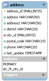
As shown in the preceding diagram the primary key is indicated by a key icon and indexed fields are indicated by a different colored diamond icon. Click the arrow to the right of the table name to toggle the display of the fields. Toggle the display of indexes and triggers in the same way.
Right-clicking a table opens a pop-up menu with the following options:
With the exception of the deletion option, these menu options function as described in Section 16.6.7.1.1, “Adding Tables to the Physical Schemata”. The behavior of the delete option is determined by your MySQL Workbench options settings. For more information, see Section 16.4.4.4, “The Model Tab”.
- 16.6.7.1.3.1. The Main Editor Window
- 16.6.7.1.3.2. The Table Tab
- 16.6.7.1.3.3. The Columns Tab
- 16.6.7.1.3.4. The Indexes Tab
- 16.6.7.1.3.5. The Foreign Keys Tab
- 16.6.7.1.3.6. The Triggers Tab
- 16.6.7.1.3.7. The Partitioning Tab
- 16.6.7.1.3.8. The Options Tab
- 16.6.7.1.3.9. The Inserts Tab
- 16.6.7.1.3.10. The Privileges Tab
The MySQL Table Editor is a component that enables the creation and modification of tables. Using the MySQL Table Editor you can add or modify a table's columns or indexes, change the engine, add foreign keys, or simply alter the table's name.
The MySQL Table Editor can be accessed from the MySQL Workbench by first
selecting the MySQL Model tab and then double
clicking a table in the Physical Schemata panel.
You can also access it from an EER Diagram by double-clicking a
table object.
Any number of tables may be edited in the MySQL Table Editor at any one time. Adding another table creates a new tab at the top of the editor. By default the MySQL Table Editor appears docked at the bottom of the application.
The MySQL Table Editor is shown in the following figure.
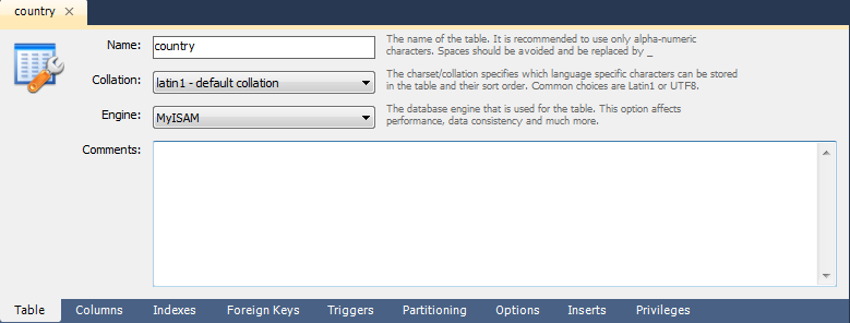
The MySQL Table Editor consists of a work space divided into the following tabs:
Table: Use this table to edit features that apply to the table as a whole
Columns: Use this tab to add or modify columns
Indexes: Use this tab to add or modify indexes
Foreign Keys: Use this tab to add or modify foreign keys
Triggers: Use this tab to add or modify triggers
Partitioning: Use this tab to manage partitioning
Options: Use this tab to add or modify various general, table and row level options
Inserts: Use this tab for writing INSERT statements
Privileges: Use this tab to set privileges on the table
Each of these tabs is discussed in further detail in the following sections.
Use this tab to edit the table name or add a comment to the table. Easily change the collation or the table engine using drop down list boxes.
The Columns tab is used to display and edit all
the column information for a table. Using this tab, you can add,
drop, and alter columns.
You can also use the column tab to change the name, data type, default value, and other properties of your table's columns.
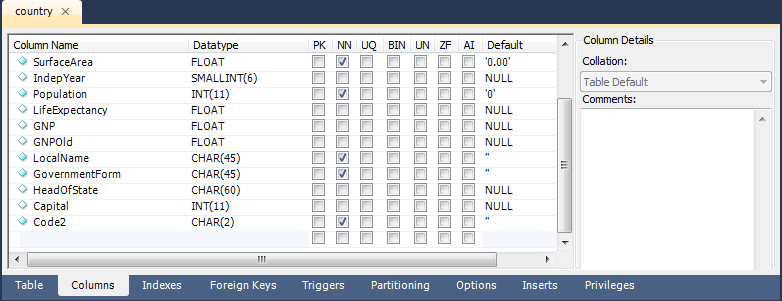
To add a column simply click the Column Name
field in an empty row and enter an appropriate value. Select a
data type from the Datatype drop down list
box. Select a column property checkbox as required according to
the following list of column properties:
PK: Primary key
NN: Not null
UQ: Unique
BIN: Binary
UN: Unsigned
ZF: Zero fill
AI: Autoincrement
Right-clicking a row under the Column Name
column opens a pop-up window with the following options:
: Move the selected column up.
: Move the selected column down.
: Select multiple contiguous columns by right-clicking and pressing the Shift key. Use the Ctrl key to select noncontiguous columns.
: Update all information in the
Columnstab.: Clear the assigned default value.
: Set the column default value to
NULL.: Set the column default value to
".
To change the name, data type, default value, or comment of a column, double-click the value you wish to change. The content then becomes editable.
You can also add column comments to the Column
Comment text area. It is also possible to set the column
collation, using the listbox in the Column
Details panel.
To the left of the column name is an icon that indicates whether
the column is a member of the primary key. If the icon is a small
key, that column belongs to the primary key, otherwise the icon is
a blue diamond or a white diamond. A blue diamond indicates the
column has NN set. To add or remove a column from the primary key,
double-click the icon. You can also add a primary key by checking
the PRIMARY KEY checkbox in the Column
Details section of the table editor.
If you wish to create a composite primary key you can select multiple columns and check the PK checkbox. However, there is an additional step that is required, you will need to click the Indexes tab, then in the Index Columns panel you need to set the desired order of the primary keys.
When entering default values, in the case of
CHAR and VARCHAR data
types MySQL Workbench will attempt to automatically add quotation
marks, if the user does not start their entry with one. For
other data types the user must manage quoting if required, as it
will not be handled automatically by MySQL Workbench.
Care must be taken when entering a default value for non-numeric
ENUM columns. When entering a non-numeric
default value it will not be automatically quoted. You must
manually add single quote characters for the default value. Note
that MySQL Workbench will not
prevent you from entering the default value without the single
quotation marks. If a non-numeric default value is entered
without quotation marks, this will lead to errors. For example,
if the model is reverse engineered, the script will contain
unquoted default values for ENUM columns and
will fail if an attempt is made to run the script on MySQL
Server.
The Indexes tab holds all index information for
your table. You can add, drop, and modify indexes using this tab.
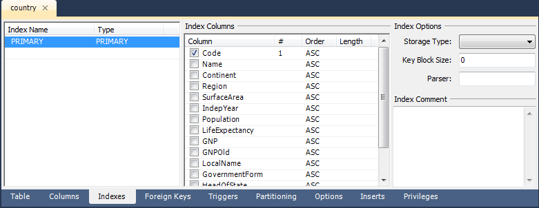
Select an index by right-clicking it. Doing this displays information about the index in the Index Columns section.
To add an index, click the last row in the index list. Enter a name for the index and select the index type from the drop down list box. Select the column or columns that you wish to index by checking the column name in the Index Columns list. You can remove a column from the index by removing the check mark from the appropriate column.
You can also specify the order of an index by choosing
ASC or DESC under the
Order column. Create an index prefix by
specifying a numeric value under the Length
column. You cannot enter a prefix value for fields that have a
data type that does not support prefixing.
To drop an index, right-click the row of the index you wish to delete and then select the menu option.
The Foreign Keys tab is organized in much the
same fashion as the Indexes tab and adding or
editing a foreign key is similar to adding or editing an index.
To add a foreign key, click the last row in the Foreign
Key Name list. Enter a name for the foreign key and
select the column or columns that you wish to index by checking
the column name in the Column list. You can
remove a column from the index by removing the check mark from the
appropriate column.
Under Foreign Key Options choose an action for the update and delete events.
The options are:
RESTRICT
CASCADE
SET NULL
NO ACTION
To drop a foreign key, right-click the row you wish to delete and then select the menu option.
To modify any of the properties of a foreign key, simply select it and make the desired changes.
The Triggers tab opens a text area for editing
an existing trigger or creating a new trigger. Create a trigger as
you would from the command line.
If you wish to enable partitioning for your table check the Enable Partitioning check box. Doing this enables the partitioning options.
The Partition By drop down list box displays the types of partitions you can create. These are:
HASHLINEAR HASHKEYLINEAR KEYRANGELIST
Use the Parameters text box to define the parameter(s) that will be supplied to the partitioning function, an integer column value for example.
Choose the number of partitions from the Partition Count drop down list box. If you wish to manually configure your partitions check the Manual check box. Doing this enables entry of values into the partition configuration table. The entries in this table are:
PartitionValuesData DirectoryIndex DirectoryMin RowsMax RowsComment
Subpartitioning is also available. For more information about partitioning see Chapter 18, Partitioning.
The Options tab enables you to set several types of options. These are grouped into the following frames:
General Options
Row Options
Storage Options
Merge Table options
Each of these is discussed in more detail in the following sections.
General Options
In the General Options frame, choose a pack
keys option. The options are Default,
Pack None, and Pack All. You
may also encrypt the definition of a table. The
AUTO_INCREMENT and delayed key update behaviors
apply only to MyISAM tables.
Row Options
To set the row format, choose the desired row format from the
drop-down list. See Section 13.5.3, “MyISAM Table Storage Formats” for
more information about the different row formats that are
available. This only applies to MyISAM tables.
These options are:
Default
Dynamic
Fixed
Compressed
Redundant
Compact
When you expect a table to be particularly large, use the
Avg. Row, Min. Rows, and
Max. Rows options to enable the MySQL server
to better accommodate your data. See
Section 12.1.14, “CREATE TABLE Syntax” for more information on how to use
these options.
Storage Options
The Storage Options section is used to
configure a custom path to the table storage and data files. This
option can help improve data integrity and server performance by
locating different tables on different hard drives. This option is
only available for MyISAM tables.
Merge Table Options
The Merge Table Options section is used to
configure MERGE tables in MyISAM. To create a MERGE table, select
MERGE as your storage engine and then specify the tables you wish
to MERGE in the Union Tables dialog.
You can also specify the action the server should take when users
attempt to perform INSERT statements on the merge table. See
Section 13.8, “The MERGE Storage Engine” for more information about
MERGE tables. Again, this only applies to MyISAM tables. You may
also select the Merge Method by selecting from
the drop down list box.
Use the Inserts tab to insert records into the
table.
To edit a record simply click the field you wish to change and enter the new data. Right-clicking a row displays a menu with the following items:
Set Field(s) to NULL:
Delete Row(s):
Copy Row Content: Copies the row to the clipboard. Strings are copied quoted, and NULLs are preserved.
Copy Row Content (unquoted): Copies the row to the clipboard. Strings are not quoted and NULLs are copied as a space.
Copy Field Content: Copies the value of the selected field to the clipboard. Strings are quoted.
Copy Field Content (unquoted): Copies the value of the selected field to the clipboard. Strings are not quoted.
Note that the insert editor features a toolbar. This has the same functionality as explained in Section 16.5.7.4.5, “Results Tabsheets” and Section 16.5.7.4.6, “Live Editing Tabsheets”. You can also hover the cursor over the toolbar to display tooltips.
Any records you add will be inserted when you forward engineer the
database (if you choose the Generate INSERT statements
for tables option).
Note when entering string values that there is slightly different behavior between the 5.0, 5.1 and 5.2 versions of MySQL Workbench.
For 5.0 and 5.1 if a string is entered without leading and trailing quotation marks, the Inserts Editor adds quoting and escapes characters that require it. However, if quoted text is entered, the Inserts Editor carries out no further checks since it assumes a correctly escaped and quoted sequence has been entered.
5.2 features a new Inserts Editor. In this case the user enters the string without quoting or escaping and the Inserts Editor takes care of all quoting and escaping as required.
It is possible to enter a function, or other expression, into a
field. If doing so, the prefix \func should
be used, to prevent MySQL Workbench from escaping quotation marks.
For example, if entering the expression
md5('fred') MySQL Workbench would generate the
code md5(\'fred\'). To prevent this enter the
expression as \func md5('fred'). This will
ensure that the quoting is not escaped.
Use the Privileges tab to assign specific roles
and privileges to a table. You may also assign privileges to a
role using the role editor. For a discussion of this topic see
Section 16.6.5.5.1, “Adding Roles”.
When this tab is first opened, all the roles that have been created are displayed in the list box on the right. Move the roles you wish to associate with this table to the Roles list box on the left. Do this by selecting a role and then clicking the button. Use the Shift key to select multiple contiguous roles and the Ctrl key to select noncontiguous roles.
To assign privileges to a role, click the role in the Roles list box. Doing this displays all available privileges in the Assigned Privileges list box. The privileges that display are:
ALLCREATEDROPGRANT OPTIONREFERENCESALTERDELETEINDEXINSERTSELECTUPDATETRIGGER
You can choose to assign all privileges to a specific user or any
other privilege as listed previously. Privileges irrelevant to a
specific table, the FILE privilege for example,
are not shown.
If a role has already been granted privileges on a specific table, those privileges show as already checked in the Assigned Privileges list box.
Foreign key constraints are supported for the
InnoDB storage engine only. For other storage
engines the foreign key syntax is correctly parsed but not
implemented. For more information see
Section 1.8.5.4, “Foreign Keys”.
Using MySQL Workbench you may add a foreign key from within the table editor or by using the relationship tools on the vertical toolbar of an EER Diagram. This section deals with adding a foreign key using the foreign key tools. To add a foreign key using the table editor see Section 16.6.7.1.3.5, “The Foreign Keys Tab”.
Using the graphical tools to add foreign keys is most effective when you are building tables from the ground up. If you have imported a database using an SQL script and do not need to add fields to your tables you may find it more effective to define foreign keys using the table editor.
There are six foreign key tools on the vertical toolbar on the left side of an EER Diagram. These tools are:
The
one-to-one non-identifying relationshiptoolThe
one-to-many non-identifying relationshiptoolThe
one-to-one identifying relationshiptoolThe
one-to-many identifying relationshiptoolThe
many-to-many identifying relationshiptoolThe
Place a Relationship Using Existing Columnstool
An identifying relationship is one where the child table cannot be uniquely identified without its parent. Typically this occurs where an intermediary table is created to resolve a many-to-many relationship. In such cases, the primary key is usually a composite key made up of the primary keys from the two original tables. An identifying relationship is indicated by a solid line between the tables and a nonidentifying relationship is indicated by a broken line.
Create or drag and drop the tables that you wish to connect. Ensure that there is a primary key in the table that will be on the “one” side of the relationship. Click on the appropriate tool for the type of relationship you wish to create. If you are creating a one-to-many relationship, first click the table that is on the “many” side of the relationship, then on the table containing the referenced key.
Doing this creates a field in the table on the many side of the
relationship. The default name of this field is
table_name_key_name where the table
name and the key name are both derived from the table containing
the referenced key.
When the many-to-many tool is active, double-clicking a table creates an associative table with a many-to-many relationship. For this tool to function there must be a primary key defined in the initial table.
Use the , menu item to set a project-specific default name for the foreign key column (see Section 16.6.5.1.5.4, “The Relationship Notation Menu Option”). To change the global default see Section 16.4.4.4, “The Model Tab”.
To edit the properties of a foreign key, double-click anywhere on the connection line that joins the two tables. Doing this opens the relationship editor.
Mousing over a relationship connector highlights the connector and the related keys as shown in the following figure.
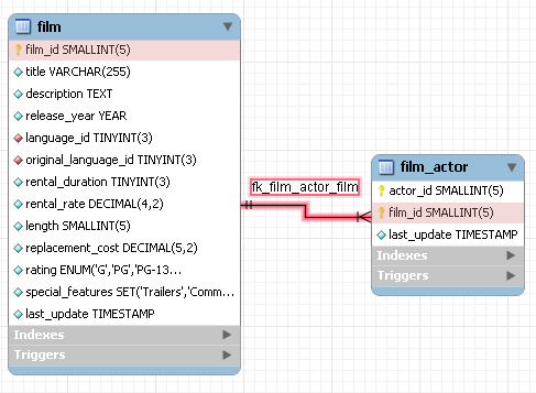
The film and the film_actor
tables are related on the film_id field and
these fields are highlighted in both tables. Since the
film_id field is part of the primary key in the
film_actor table, a solid line is used for the
connector between the two tables.
If the placement of a connection's caption is not suitable, you
can change its position by dragging it to a different location. If
you have set a secondary caption, its position can also be
changed. (For more information about secondary captions see
Section 16.6.7.2.3, “The Properties of a Connection”. Where the notation
style allows, Classic for instance, the
cardinality indicators can also be repositioned.
The relationship notation style in Figure 16.48, “The Relationship Connector” is the default, crow's foot. If you are using a commercial version of MySQL Workbench you can change this. For more information, see Section 16.6.5.1.5.4, “The Relationship Notation Menu Option”.
You can select multiple connections by holding down the Ctrl key as you click a connection. This can be useful for highlighting specific relationships on an EER diagram.
Double-clicking a relationship on the EER diagram canvas opens up the relationship editor. This has two tabs: Relationship, and Foreign Key.
The Relationship tab
In the Relationship tab you can set the
caption of a relationship using the Caption
text box. This name displays on the canvas and is also the name
used for the constraint itself. The default value for this name is
fk_.
Use the ,
menu item to set a project-specific default name for foreign keys.
To change the global default see
Section 16.4.4.4, “The Model Tab”.
source_table_destination_table
You can also add a secondary caption to a relationship and also a comment.
The Visibility Settings frame is used to
determine how the relationship is displayed on the EER Diagram
canvas. Fully Visible is the default but you
can also choose to hide relationship lines or to use split lines.
The split line style is pictured in the following:
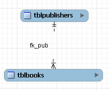
A broken line connector is used to indicate a nonidentifying relationship. The split line style can be used with either an identifying relationship or a nonidentifying relationship. It is used for display purposes only and does not indicate anything about the nature of a relationship.
To set the notation of a relationship go to the , menu item. For more information, see Section 16.6.5.1.5.4, “The Relationship Notation Menu Option”.
The Foreign Key tab
The Foreign Key tab contains several frames: Referencing Table, Cardinality and Referenced Table.
The Mandatory checkboxes are used to select
whether the referencing table and the referenced table are
mandatory. The default value for both of these constraints is
true, which is indicated by the checkboxes
being checked.
In the Cardinality frame there is a set of radio buttons that allow you to choose whether the relationship is one-to-one or one-to-many. There is also a checkbox that enables you to specify whether the relationship is an identifying relationship.
To select a connection, right-click it. When a connection is selected it is highlighted and its properties are displayed in the properties palette. The properties of a connection are quite different from the properties of other objects. These properties are described in the following list:
caption: The name of the object. By default this property is centered above the connection line. Its default value is the name of the foreign key.captionXOffs: The “x” offset of the caption.captionYOffs: The “y” offset of the caption.comment: The comment associated with the relationship.drawSplit: Whether or not to show the relationship as a continuous line.endCaptionXOffs: The “x” termination point of the caption offset.endCaptionYOffs: The “y” termination point of the caption offset.extraCaption: A secondary caption. The default location for this extra caption is centered beneath the connection line.extraCaptionXOffs: The “x” offset of the secondary caption.extraCaptionYOffs: The “y” offset of the secondary caption.mandatory: Whether or not the entities are mandatory. For more information, see Section 16.6.7.2.2, “The Relationship Editor”.many: False if the relationship is a one-to-one relationship.middleSegmentOffset: The offset of the middle section of the connector.modelOnly: when this is set the connection will not be propagated to the DDL. It is just a logical connection drawn on a diagram. This is used, for example, when drawing MyISAM tables with a visual relationship, but with no foreign keys.name: The name used to identify the connection on the EER Diagram canvas. Note that this is not the name of the foreign key.referredMandatory: Whether or not the referred entity is mandatorystartCaptionXOffs: The start of the “x” offset of the caption.startCaptionYOffs: The start of the “y” offset of the caption.
In most cases you can change the properties of a relationship
using the relationship editor rather than the
Properties palette.
If you make a relationship invisible by hiding it using the relationship editor's Visibility Settings, and then the relationship editor is closed, you will no longer be able to select the relationship to bring up its relationship editor. To make the relationship visible again you will need to expand the table object relating to the relationship in the Layers palette and select the relationship object. Once selected, you can edit the object by right-clicking, and selecting . You can then set the Visibility Settings to Fully Visible. The relationship will then be visible in the EER Diagram window.
You can add views to a database either from the Physical
Schemata section of the MySQL Model
page or from the EER Diagram.
Double-clicking the Add View icon in the
Physical Schemata section of the MySQL
Model page adds a view with the default name of
view1. If a view with this name already exists,
the new view is named view2.
Adding a new view automatically opens the view editor docked at the bottom of the application. Using the view editor is described in Section 16.6.7.3.3, “The View Editor”.
Right-clicking a table opens a pop-up menu with the following options:
If the table editor is not open the option opens it. If it is already open, the selected table replaces the previous one. opens a new view editor tab.
The cut and copy options are useful for copying views between
different schemata and
copies the CREATE VIEW statement to the
clipboard.
Use the to remove a view from the database. There will be no confirmation dialog box.
Any views added to the Physical Schemata also
show up in the Catalog palette on the left side
of the application. They may be added to an EER Diagram, when in
EER Diagram view, by dragging and dropping them from this palette.
Views can also be added to an EER Diagram using the
View tool on the vertical toolbar. To do this
make sure that the EER Diagram tab is selected,
and left-click the view icon on the vertical toolbar. The view
icon is the two overlapping rectangles found below the table icon.
Clicking this icon changes the mouse pointer to a view pointer. You can also change the mouse pointer to a view pointer by pressing the V key.
Choosing the View tool changes the contents of
the toolbar that appears immediately below the main menu bar. When
the Views pointer is active, this toolbar
contains a drop down list box of schemata and a drop down color
chart. Use these list boxes to select the appropriate schema and
color accent for the new view. Make sure that you associate the
new view with a database. The color of your view can easily be
changed later using the Properties palette.
Create a view by clicking anywhere on the EER Diagram canvas. This
creates a new view with the default name view1.
To revert to the default mouse pointer, click the arrow icon at
the top of the vertical toolbar.
Right-clicking a view opens a pop-up menu. With the exception of the delete option, these menu options function as described in Section 16.6.7.3.1, “Adding Views to the Physical Schemata”. The behavior of the delete option is determined by your MySQL Workbench options settings. For more information, see Section 16.4.4.4, “The Model Tab”.
You can invoke the view editor by double-clicking a view object on
the EER Diagram canvas or by double-clicking a view in the
Physical Schemata section on the MySQL
Model page. Doing this opens the view editor docked at
the bottom of the application. Double-clicking the title bar
undocks the editor. Do the same to redock it. Any number of views
may be open at the same time. Each additional view appears as a
tab at the top of the view editor.
There are three tabs at the bottom of the view editor, the View, Comments, and the Privileges tabs. Navigate between different tabs using the mouse or from the keyboard by pressing Ctrl + Alt + Tab.
The View Tab
From the View tab of the view editor you can
perform the following tasks:
Rename the view using the Name text box.
Enter the SQL to create a view using the SQL text area.
Comment a view using the Comments text area.
The Comments
Tab
This tab enables you to enter comments for a particular view.
The Privileges
Tab
The Privileges tab of the view editor functions
in exactly the same way as the Privileges tab
of the table editor. For more information, see
Section 16.6.7.1.3.10, “The Privileges Tab”.
When you select a view on the EER Diagram canvas, its properties
are displayed in the Properties palette. Most
of the properties accessible from the
Properties palette apply to the appearance of a
view on the EER Diagram canvas.
For a list of the properties accessible through the
Properties palette see
Section 16.6.5.11, “The Properties Palette”.
You can add Routine Groups to a database either from the Physical Schemata section of the MySQL Model page or from an EER Diagram. Routines may only be added from the Physical Schemata section of the MySQL Model page.
To view an existing schema, along with its Routines and Routine Groups, select , from the main menu. After the schema has been added to the current model, you can see the schema objects on the Physical Schemata panel on the MySQL Model page. The Routines and Routine Groups are listed there.
MySQL Workbench unifies both stored procedures and stored functions into one logical object called a Routine. Routine Groups are used to group routines that are related. You can decide how many Routine Groups you want to create and you can use the Routine Group Editor to assign specific routines to a group, using a drag and drop interface.
When designing an EER Diagram you can place the Routine Groups on the canvas by dragging them from the Catalog Palette. Placing individual routines on the diagram is not permitted, as it would clutter the canvas.
Double-clicking the Add Routine icon in the
Physical Schemata section of the
MySQL Model page adds a routine with the
default name of routine1. If a routine with
this name already exists, the new routine is named
routine2.
Adding a new routine automatically opens the routine editor docked at the bottom of the application. Using the routine editor is described in Section 16.6.7.4.1.2, “The Routine Editor”.
Right-clicking a routine opens a pop-up menu with the following options:
The option opens the routine editor.
The cut and paste options are useful for copying routines between different schemata.
Deleting the code for routine from the Routines tab of the Routine Group Editor will result in removal of the routine object from the model.
To remove a routine from a routine group use the controls on the Routine Group tab of the Routine Group Editor.
The action of the delete option varies depending upon the way you have configured MySQL Workbench. For more information, see Section 16.4.4.4, “The Model Tab”.
You can invoke the routine editor by double-clicking a routine
in the Physical Schemata section on the
MySQL Model page. Doing this opens the
routine editor docked at the bottom of the application. Any
number of routines may be open at the same time. Each additional
routine appears as a tab at the top of the routine editor.
There are two tabs at the bottom of the routine editor, the Routine and the Privileges tabs. Navigate between different tabs using the mouse or from the keyboard by pressing Ctrl + Alt + Tab.
From the Routine tab of the routine editor
you can perform the following tasks:
Rename the routine using the Name text box.
Enter the SQL to create a routine using the SQL text area.
The Privileges tab of the routine editor
functions in exactly the same way as the
Privileges tab of the table editor. For
more information, see
Section 16.6.7.1.3.10, “The Privileges Tab”.
Privileges are only available in the Standard Edition of MySQL Workbench.
Double-clicking the Add Routine Group icon in
the Physical Schemata section of the
MySQL Model page adds a routine with the
default name of routines1. If a routine group
with this name already exists, the new routine group is named
routines2.
Adding a new routine group automatically opens the routine groups editor docked at the bottom of the application. Using the routine groups editor is described in Section 16.6.7.4.2.3, “The Routine Group Editor”.
Right-clicking a routine group opens a pop-up menu with the following options:
The option opens the routine group editor. Using the routine group editor is described in Section 16.6.7.4.2.3, “The Routine Group Editor”.
The cut and paste options are useful for copying routine groups between different schemata.
Deleting a routine group from the MySQL Model
page removes the group but does not remove any routines
contained in that group.
Any routine groups added to the Physical
Schemata also show up in the
Catalog palette on the right side of the
application. They may be added to an EER Digram by dragging and
dropping them from this palette.
Routine groups can also be added to an EER Diagram using the
Routine Groups tool on the vertical toolbar.
To do this make sure that the EER Diagram tab
is selected, and right-click the routine groups icon on the
vertical toolbar. The routine groups icon is immediately above
the lowest toolbar separator.
Clicking the mouse on this icon changes the mouse pointer to a routine group pointer. You can also change the mouse pointer to a routine pointer by pressing the G key.
Choosing the Routine Group tool changes the
contents of the toolbar that appears immediately below the menu
bar. When the Routine Groups pointer is
active, this toolbar contains a drop down list box of schemata
and a drop down color chart. Use these list boxes to select the
appropriate schema and color accent for the new routine group.
Make sure that you associate the new routine group with a
database. The color of your routine group can easily be changed
later using the Properties palette.
Create a routine group by clicking anywhere on the EER Diagram
canvas. This creates a new routine group with the default name
routines1. To revert to the default mouse
pointer, click the arrow icon at the top of the vertical
toolbar.
Right-clicking a routine group opens a pop-up menu. With the exception of the delete option and rename options these menu options function as described in Section 16.6.7.4.2.1, “Adding Routine Groups to the Physical Schemata”. There is no rename option and the behavior of the delete option is determined by your MySQL Workbench options settings. For more information, see Section 16.4.4.4, “The Model Tab”.
You can invoke the routine group editor by double-clicking a
routine group object on the EER Diagram canvas or by double
clicking a routine group in the Physical
Schemata section on the MySQL Model
page. Doing this opens the routine group editor docked at the
bottom of the application. Double-clicking the title bar undocks
the editor. Do the same to redock it. Any number of routine
groups may be open at the same time. Each additional routine
group appears as a tab at the top of the routine editor,
There are two tabs at the bottom of the routine editor, the Routine group and the Privileges tabs. Navigate between different tabs using the mouse or from the keyboard by pressing Ctrl + Alt + Tab.
From the Routine Groups tab of the routine
groups editor you can perform the following tasks:
Rename the routine group using the Name text box.
Add routines to the group by dragging and dropping them.
Add comments to the routine group.
The Privileges tab of the routine group
editor functions in exactly the same way as the
Privileges tab of the table editor. For
more information, see
Section 16.6.7.1.3.10, “The Privileges Tab”.
Privileges are only available in the Standard Edition of MySQL Workbench.
When you select a routine group on the EER Diagram canvas, its
properties are displayed in the Properties
palette. All of the properties accessible from the
Properties palette apply to the appearance
of a routine group on the EER Diagram canvas.
For a list of the properties accessible through the
Properties palette see
Section 16.6.5.11, “The Properties Palette”.
You can add layers to a database only from an EER Diagram. Layers are used to help organize objects on the canvas. Typically, related objects are added to the same layer; for example, you may choose to add all your views to one layer.
Layers are added to an EER Diagram using the
Layer tool on the vertical toolbar. To do this
select an EER Diagram tab and right-click the
layer icon on the vertical toolbar. The layer icon is the
rectangle with an ‘L’ in the lower
left corner and it is found below the eraser icon.
Clicking the mouse on this icon changes the mouse pointer to a layer pointer. You can also change the mouse pointer to a layer pointer by pressing the L key.
Choosing the Layer tool changes the contents of
the toolbar that appears immediately below the menu bar. When the
Layers pointer is active, this toolbar contains
a drop down color chart. Use this list box to select the color
accent for the new layer. The color of your layer can easily be
changed later using the Properties palette.
Create a layer by clicking anywhere on the EER Diagram canvas and,
holding the left mouse button down, draw a rectangle of a suitable
size. This creates a new layer with the default name
layer1. To revert to the default mouse pointer,
click the arrow icon at the top of the vertical toolbar.
Find below an image of a layer containing a number of views:
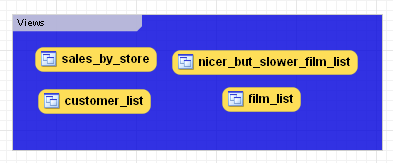
Use the name property of the
Properties palette to change the name of a
layer.
Right-clicking a layer opens a pop-up menu with the following options:
The cut and copy options are useful for copying layers between different schemata.
Since layers are not schema objects, no confirmation dialog box opens when you delete a layer regardless of how you have configured MySQL Workbench. Deleting a layer does not delete schema objects from the catalog.
Add an object to a layer by dragging and dropping it directly
from the Catalog palette onto a layer. If you
pick up an object from an EER diagram you need to press
Ctrl as you drag it on to the layer, otherwise
it will not be "locked" inside the layer.
Locking objects to a layer prevents their accidental removal. You cannot remove them simply by clicking and dragging; in order to remove an object, you also need to press the Ctrl key while dragging it.
As a visual cue that the object is being "locked", the outline of the layer is highlighted as the object is dragged over it.
If you drag a layer over a table object, the table object will automatically be added to the layer. This also works for multiple table objects.
Note that layers cannot be nested, that is, a layer cannot contain another layer object.
When you select a layer on the EER Diagram canvas, its properties
are displayed in the Properties palette. The
properties accessible from the Properties
palette apply to the appearance of a layer on the EER Diagram
canvas.
In some circumstances you may want to make a layer invisible. To
do this, select the layer and, in the
Properties palette, set the
visible property to False.
To locate an invisible object, open the Layers
palette and select the object by double-clicking it. Once an
object is selected you can reset the visible
property from the Properties palette.
For a list of the properties accessible through the
Properties palette see
Section 16.6.5.11, “The Properties Palette”. In addition to the
properties listed there, a layer also has a
description property. Use this property to
document the purpose of the layer.
You can add notes to a database only from the Model
Notes section of the MySQL Model page.
Notes are typically used to help document the design process.
Double-clicking the Add Note icon in the
Model Notes section of the MySQL
Model page adds a note with the default name of
note1. If a note with this name already exists,
the new note is named note2.
Adding a new note automatically opens the note editor docked at the bottom of the application. Using the note editor is described in Section 16.6.7.6.2, “The Note Editor”.
Right-clicking a note opens a pop-up menu with the following options:
The option opens the note editor. Using the note editor is described in Section 16.6.7.6.2, “The Note Editor”.
The cut and copy options are useful for copying notes between different schemata.
Notes can only be added on the MySQL Model
page.
You can invoke the note editor by double-clicking a note object in
the Model Note section on the MySQL
Model page. Doing this opens the note editor docked at
the bottom of the application. Double-clicking the note tab
undocks the editor. Double-click the title bar to redock it. Any
number of notes may be open at the same time. Each additional note
appears as a tab at the top of the note editor.
Using the editor you can change the name of a note or its contents.
Text objects are applicable to an EER diagram only. They can be used for documentation purposes, for example, to explain a grouping of schema objects. They are also useful for creating titles for an EER diagram should you decide to export a diagram as a PDF or PNG file.
Text objects can be added to an EER Diagram using the
Text Object tool on the vertical toolbar. To do
this make sure that the EER Diagram tab is
selected, and right-click the text object icon on the vertical
toolbar. The text object icon is the rectangular icon found below
the label icon.
Clicking the mouse on this icon changes the mouse pointer to a text object pointer. You can also change the mouse pointer to a text object pointer by pressing the N key.
Choosing the Text Object tool changes the
contents of the toolbar that appears immediately below the menu
bar. When the Text Object pointer is active,
this toolbar contains a drop down color chart. Use this list box
to select the color accent for the new text object. The color of
your text object can easily be changed later using the
Properties palette.
Create a text object by clicking anywhere on the EER Diagram
canvas. This creates a new text object with the default name
text1. To revert to the default mouse pointer,
click the arrow icon at the top of the vertical toolbar.
Right-clicking a text object opens a pop-up menu. These menu options are identical to the options for other objects. However, since a text object is not a database object, there is no confirmation dialog box when you delete a text object.
You can invoke the text object editor by double-clicking a text object on the EER Diagram canvas. Doing this opens the editor docked at the bottom of the application. Double-clicking the text object table undocks the editor. Double-click the title bar to redock it. Any number of text objects may be open at the same time. Each additional text objects appears as a tab at the top of the text editor.
Using the editor you can change the name of a text object or its contents.
When you select a text object on the EER Diagram canvas, its
properties are displayed in the Properties
palette. Most of the properties accessible from the
Properties palette apply to the appearance of
a view on the EER Diagram canvas.
For a list of the properties accessible through the
Properties palette see
Section 16.6.5.11, “The Properties Palette”.
There is no property in the Properties
palette for changing the font used by a text object. To change
the font used by a text object choose the
Appearance tab of the Workbench Preferences
dialog. For more information, see
Section 16.4.4.7, “The Appearance Tab”.
Images only exist on the EER Diagram canvas; you can only add them from the EER Diagram window.
Images can be added to an EER Diagram using the
Image tool on the vertical toolbar. To add an
image make sure that the EER Diagram tab is
selected, and right-click the image icon on the vertical toolbar.
The image icon is the icon just above the table icon.
Clicking the mouse on this icon changes the mouse pointer to an image pointer. You can also change the mouse pointer to an image pointer by pressing the I key.
Create a image by clicking anywhere on the EER Diagram canvas. This opens a file open dialog box. Select the desired image, and close the dialog box to create an image on the canvas. To revert to the default mouse pointer, click the arrow icon at the top of the vertical toolbar.
Right-clicking this object opens a pop-up menu with the following options:
These menu options function in exactly the same way as they do for other objects on an EER diagram. However, images are not database objects so there is no confirmation dialog box when they are deleted.
You can invoke the image editor by double-clicking a image object on an EER Diagram canvas. Doing this opens the image editor docked at the bottom of the application. Double-clicking the image editor tab undocks the editor. Double-click the title bar to redock it. Any number of images may be open at the same time. Each additional image appears as a tab at the top of the image editor,
Using MySQL Workbench you can reverse engineer a database using a MySQL create script or you can connect to a live MySQL server and import a single database or a number of databases. Reverse engineering using a MySQL DDL script applies to all versions of MySQL Workbench; reverse engineering a database directly from a MySQL server applies to commercial versions of MySQL Workbench only.
Reverse engineering using a create script is done by using the
, ,
menu
options. Doing this opens a file open dialog box with the default
file type set to an SQL script file, a file with the extension
sql.
You can create a data definition (DDL) script by executing the
mysqldump command.
Using the db_name
--no-data >
script_file.sql--no-data option ensures that the
script contains DDL statements only. However, if you are working
with a script that also contains DML statements you need not
remove them; they will be ignored.
If you plan to redesign a database within MySQL Workbench and then
export the changes, be sure to retain a copy of the original DDL
script. You will need the original script to create an
ALTER script. For more information, see
Section 16.6.7.10.1.2, “Altering a Schema”.
Use the --databases option with
mysqldump if you wish to create the database as
well as all its objects. If there is no CREATE DATABASE
statement in your
script file, you must import the database objects into an existing
schema or, if there is no schema, a new unnamed schema is created.
db_name
If your script creates a database, a new physical schemata tab is
created on the MySQL Model page.
Any database objects may be imported from a script file in this fashion; tables, views, routines, and routine groups. Any indexes, keys, and constraints are also imported. Objects imported using an SQL script can be manipulated within MySQL Workbench in the same way that any other objects can.
Before exiting, be sure to save the schema. Choose the
, menu item and the
reverse-engineered database will be saved as a MySQL Workbench
file with the extension mwb.
See Section 16.6.8.1, “Importing a Data Definition SQL Script” for a tutorial on
reverse engineering the sakila database.
This section explains how to reverse engineer a live database using MySQL Workbench.
Select the , menu item from the main menu. Doing this opens the Reverse Engineer Database wizard.
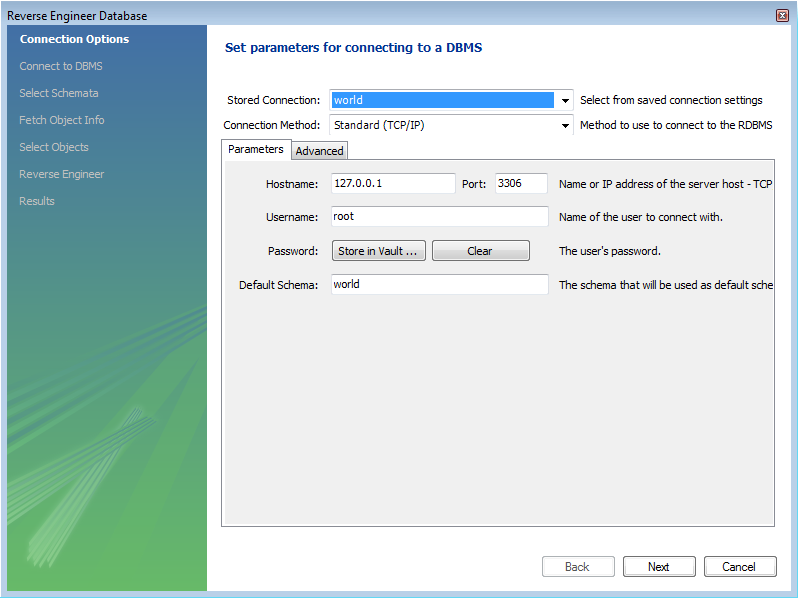
The first page of the wizard enables you to set up a connection to the live database you wish to reverse engineer. This enables you to set up a new connection, or select a previously created connection. Typical information required for the connection includes hostname, username and password.
Once this information has been entered, or you have selected a stored connection, click the button to proceed to the next page:
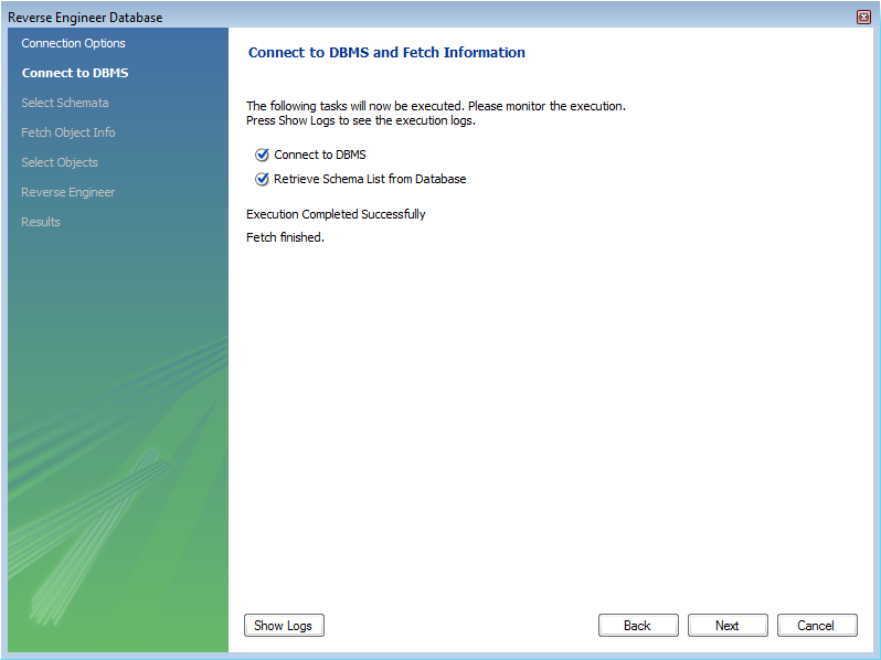
Review the displayed information to make sure that the connection did not generate errors, then click .
On the next page you can select the database schema you want to connect to among those available on the server. Simply click the checkbox or checkboxes associated with the schema you wish to process:

Once you have selected the desired schema, click the button to continue.
The wizard then displays the tasks it carried out and summarizes the results of the operation:

Review the results before clicking to continue.
The next page is the Select Objects page. It is
sectioned off by object type. This screen is of special interest
if you do not wish to import all the objects from the existing
database—this screen gives you the option of filtering which
objects are imported. Each section has a button. Click this button if you do not want to
import all the objects of a specific type.
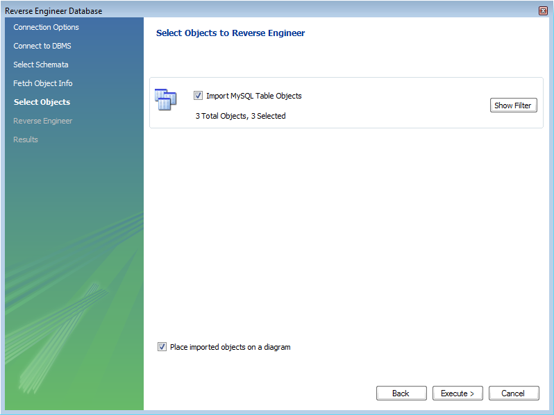
For the Import MySQL Table Objects section, if you click the button the following page is displayed:
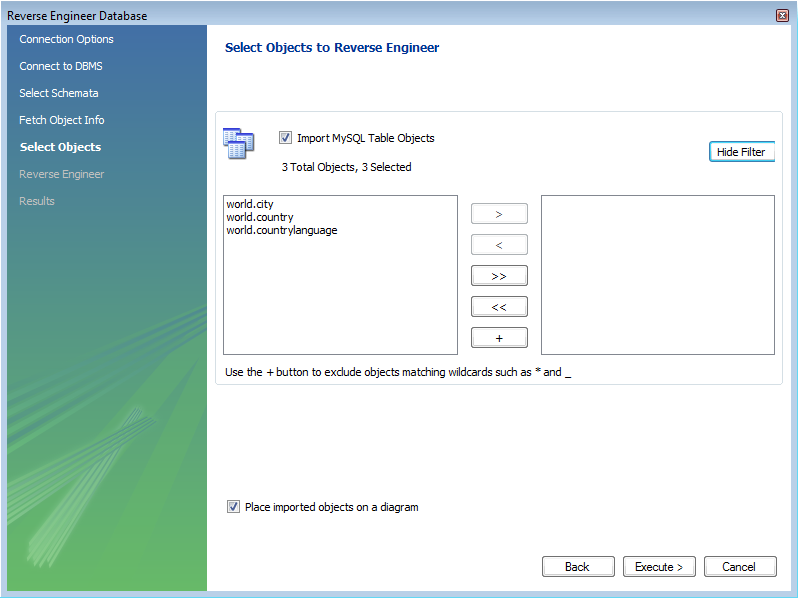
This enables you to select specific tables that you wish to import. Having selected the desired tables you can optionally hide the filter by clicking the button.
The other sections, such as MySQL Routine Objects, have similar filters available.
You can click to continue to the next page.
The wizard then displays the tasks that have been carried out and whether the operation was successful or not. If errors were generated then you can click the button to see the nature of the errors.

Click to continue to the next page.
The final screen of the wizard provides a summary of the reverse engineered objects:

Click to exit the wizard.
Before exiting MySQL Workbench be sure to save the schema. Choose the
, menu item and the
reverse-engineered database will be saved as a MySQL Workbench
file with the extension mwb.
During reverse engineering the application checks for tables and views that duplicate existing names and disallows duplicate names if necessary. If you attempt to import an object that duplicates the name of an existing object you will be notified with an error message. To see any errors that have occurred during reverse engineering you can click the button . This will create a panel containing a list of messages, including any error messages than may have been generated. Click the button to close the panel.

If you wish to import an object with the same name as an existing object, rename the existing object before reverse engineering.
If you import objects from more than one schema, there will be a
tab in the Physical Schemata section of the
MySQL Model page for each schema imported.
You cannot reverse engineer a live database that has the same name as an existing schema. If you wish to do this, first rename the existing schema.
It is possible to forward engineer a database using an SQL script or by connecting to a live database.
To create a script of your database model use the
option found under the
menu. You may export a script to alter an
existing database or create a new database. The script to create a
database is similar to the one created using the
mysqldump db_name
command.
If you choose to create a database, there are a number of export options that you may choose from.
Selecting , , will start the Forward Engineer SQL Script wizard. The first page of the wizard is:
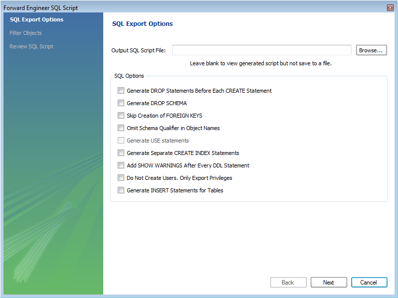
The SQL Export Options displays the following facilities:
Output SQL Script File
You can enter the name of your output file by entering it into the Output SQL Script File text box, or by using the button to select a file. If this text box is left blank you will be able to view the generated script, but it will not be saved to a file.
Generate DROP Statements Before Each CREATE Statement
Omit Schema Qualifier in Object Names
Generate Separate CREATE INDEX Statements
Choosing this option creates separate statements for index
creation instead of creating indexes as part of a
CREATE TABLE statement.
Add SHOW WARNINGS after every DDL statement
Do Not Create Users. Only Export Privileges
To update the privileges of existing users as opposed to
creating new users, select this check box. Exporting privileges
for nonexistent users will result in errors when you execute the
CREATE script. Exporting users that already
exist, will also result in an error.
Generate INSERT Statements for Tables
If you have added any records to a table using the Insert tab of the MySQL Table Editor, choose this option. For more information about inserting records see Section 16.6.7.1.3.9, “The Inserts Tab”.
Clicking takes you to the SQL Object Export Filter page where you can select the objects you wish to export.
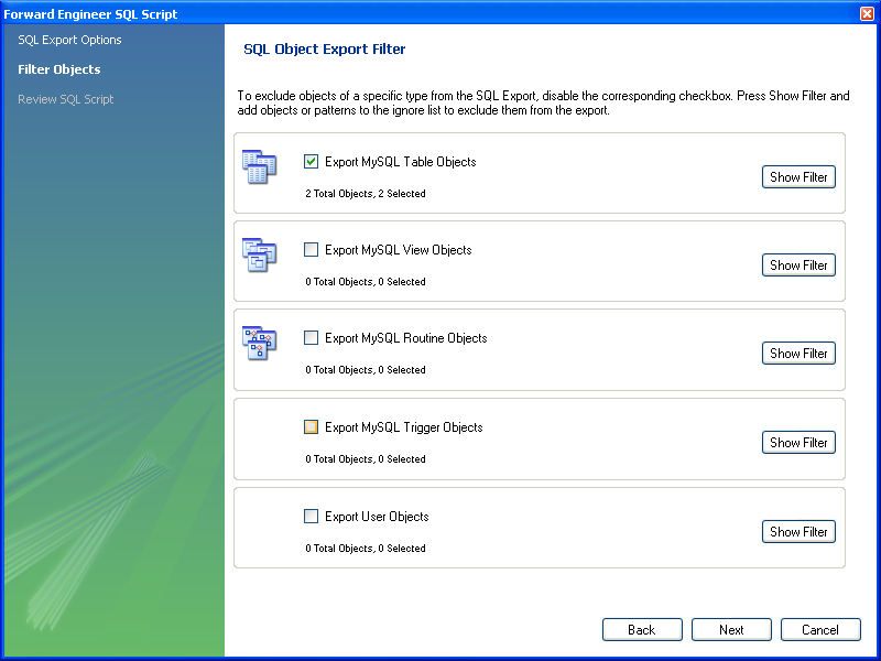
Precise control over the objects to be exported can be fine tuned by clicking the button. Once the objects to be exported have been selected it is possible to reduce the expanded panel by clicking the same button, now labelled .
Having selected the objects you wish to export you can click the button to review the script that has been generated:
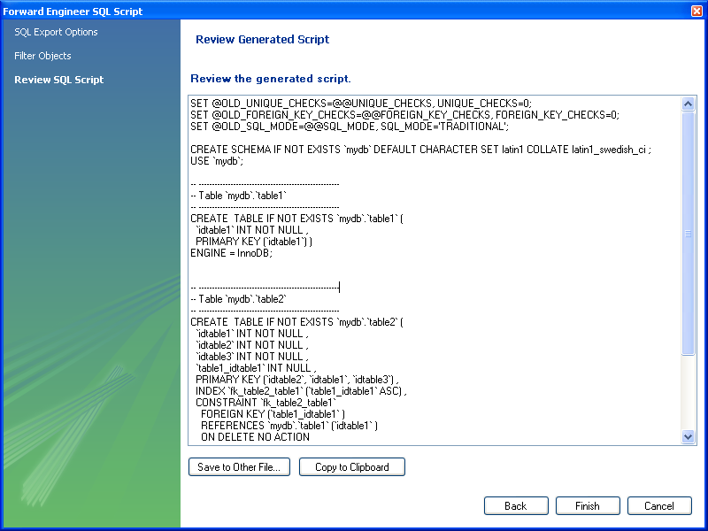
The button saves the script file and exits. You may return to the previous screen using the button.
You can then use the saved script to create a database.
The menu option for altering a schema, , is used for updating a database that has been redesigned within MySQL Workbench. Typically, this option is used when the SQL script of a database has been imported into MySQL Workbench and changed, and then you want to create a script that can be run against a database to alter it to reflect the adjusted model. For instructions on importing a DDL script see Section 16.6.7.9.1, “Reverse Engineering Using a Create Script”.
Select , , to start the Foward Engineer an ALTER Script wizard. You will be presented with the first page:

This first screen enables you to select a SQL script and compare it with the model currently in MySQL Workbench. The difference between the two models will be used to create an alter script that can be used to modify the target schema so that it matches the model held in MySQL Workbench. You can also simply view the script generated, rather than saving it to a file, by leaving the Output File text box empty.
The script selected as the Input File must use full schema
qualifiers, such as schema_name.table_name,
otherwise MySQL Workbench will not be able to generate a useable
alter script.
Pressing brings you to the Review SQL Script screen.
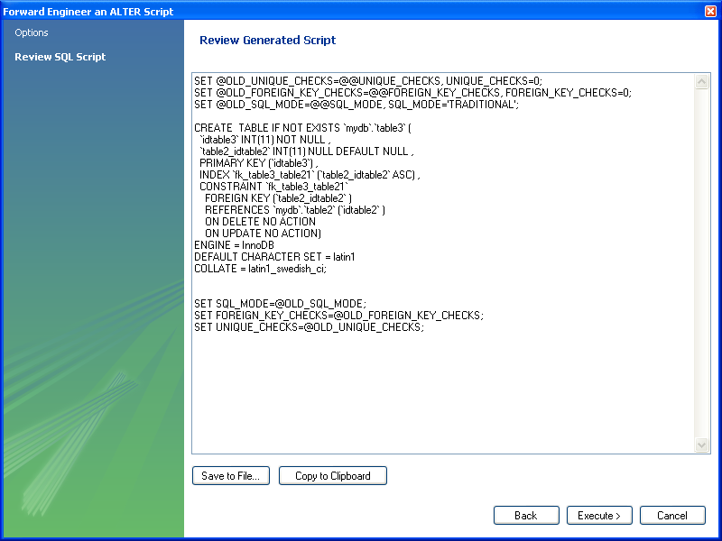
Here you can review and change the alter script that will be
generated. Make any changes you wish and, if you are happy with
the changes, save the ALTER script to file
using the button. You
can also click the button to
write the script to the previously specified output file.
The generated script can then be used to update the database.
Use forward engineering to export your schema design to a MySQL server.
Select the schema that you wish to forward engineer and then choose , option from the main menu.
The first page to be displayed is Catalog Validation (validation is only available in the Standard Edition):
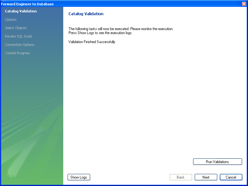
Click to validate the catalog.
Click the to continue.
The next page enables you to set options for the database to be created. These options are as described in Section 16.6.7.10.1.1, “Creating a Schema”:

Select the required options and then click .
The next page enables you to select the objects to forward engineer:
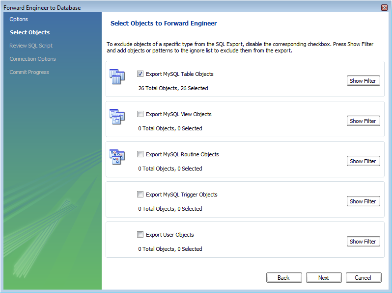
To select a subset of objects to forward engineer use the / button, and then select specific objects. Once you have selected your objects click to continue
On the Review Script page you may review and
edit the SQL script that will be executed:
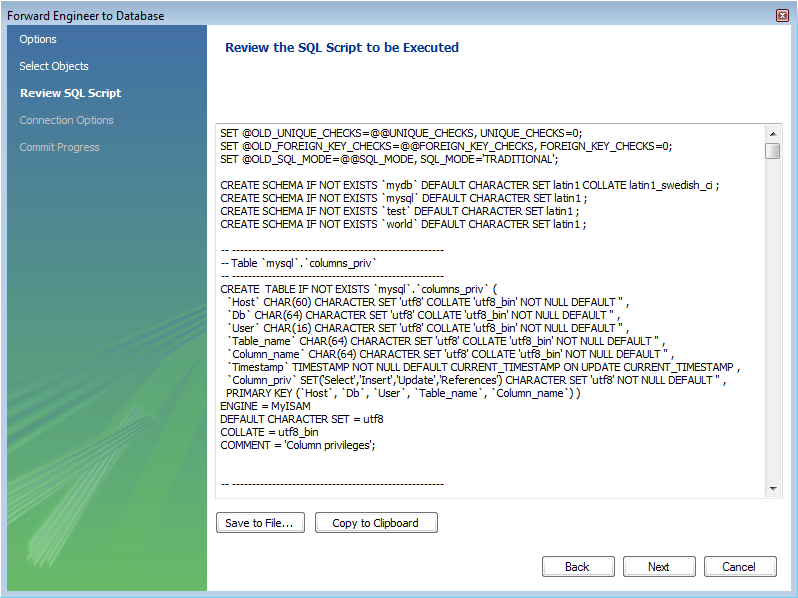
Click to continue if you are satisfied with the generated script.
The next step of the process is to connect to a MySQL server in order to create the new database schema. This page enables you to use a previously stored connection, or enter the connection parameters:

Once the connection parameters have been set click . The next page of the wizard displays the results of the forward engineering process:
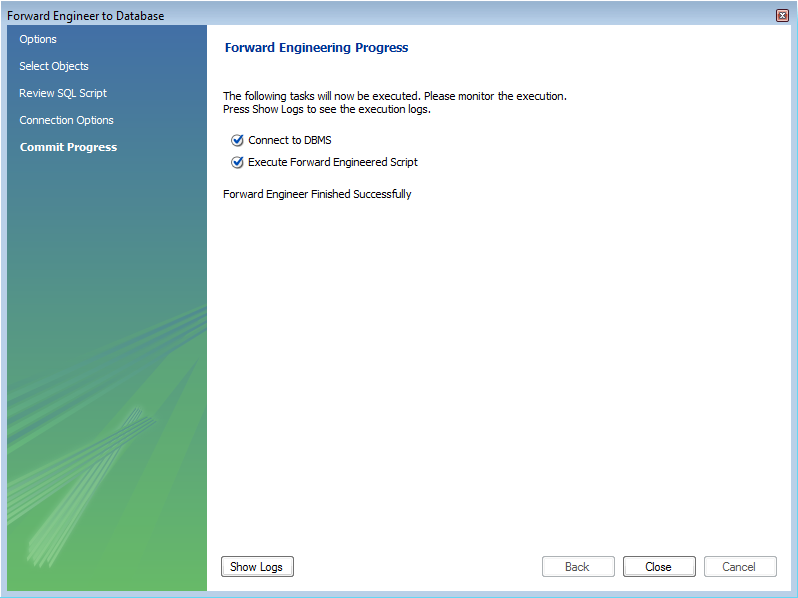
You can confirm the creation of the schema by connecting to the
target MySQL server and issuing the SHOW
DATABASES; command.
It is possible to synchronize a model in MySQL Workbench with a live database. By default, the synchronization process will change the live database to be the same as the model, but this is configurable during the synchronization process.
MySQL Workbench enables control over the direction of synchronization, and the objects synchronized, in a completely flexible way. You can choose to synchronize only certain tables, allow synchronization to the live database only, allow synchronization from the live database to the model only, or a combination of directions. In effect you have complete control as to whether the synchronization is unidirectional or bidirectional, and which objects exactly are subject to synchronization. This is all controlled in the Select Changes to Apply page of the synchronization wizard:
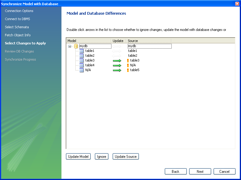
In the above example the live database consists of
table1, table2 and
table3. In MySQL Workbench an additional table,
table4, has been created, along with a
relationship between it and table3. Further,
table5 exists in the live database, but not in
the model. The actions that are configured to occur would result
in table3 being altered (to include the
relationship with table4),
table4 being created and
table5 being dropped, in the live database. It
is possible to reconfigure this though.
The next example shows how the direction of synchronization can be changed:

In this case the synchronization direction has been changed so
that rather than the default action of table5
being dropped from the live database, it will be incorporated into
the MySQL Workbench model.
For convenience the wizard provides three additional buttons to allows synchronization directions to be applied to a group of selected changes. The button causes the selected changes to only be applied to the model itself:
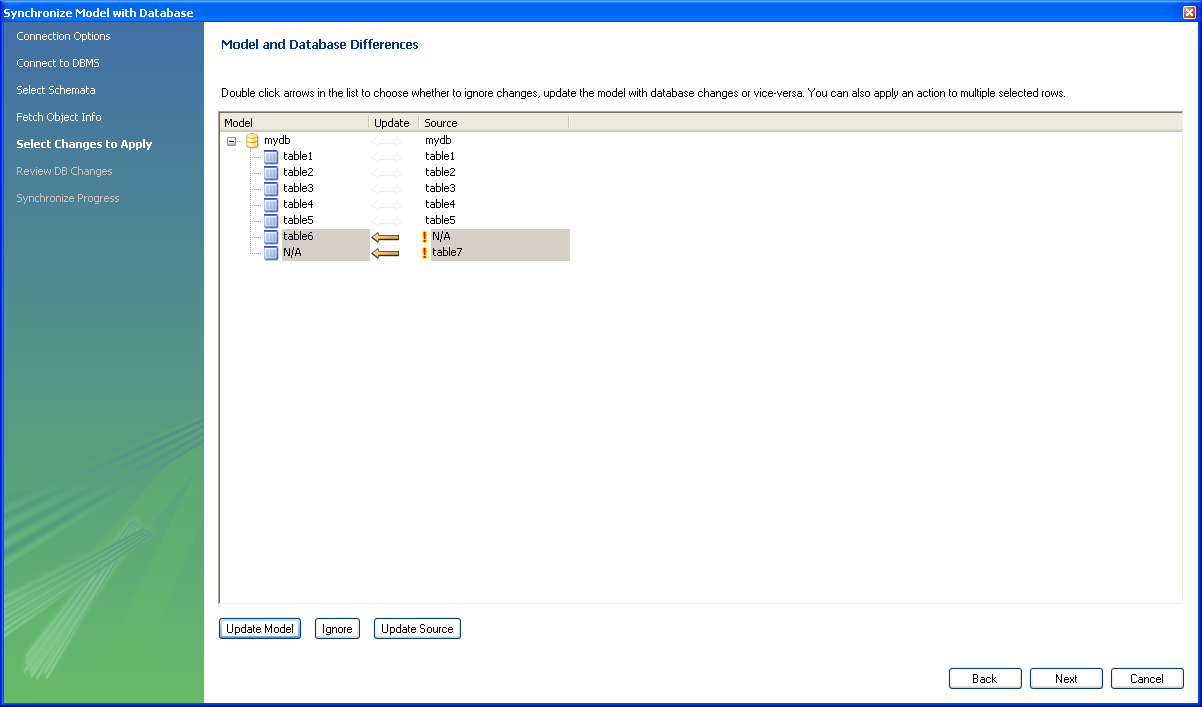
In the above example table7 would be added to
the model.
The button causes the selected changes to be ignored, no synchronization will take place for those changes:

In the above example no changes would take place.
The button causes the selected changes to only update the live database:
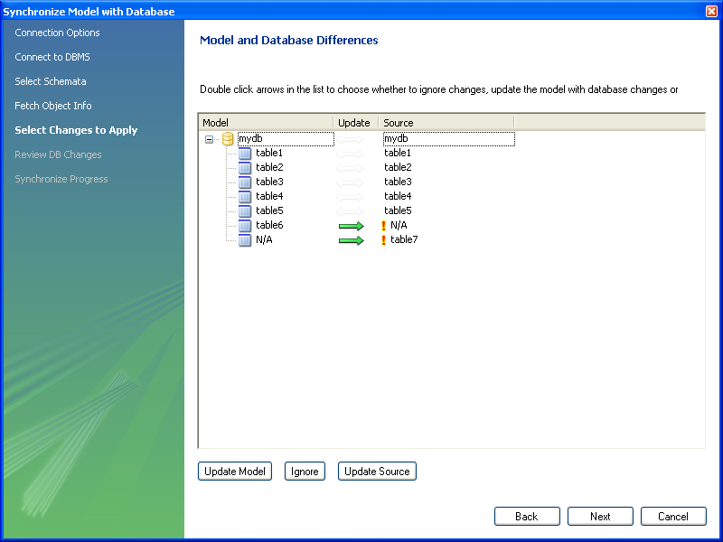
In this example table6 would be added to the
live database and table7 would be dropped from
the live database.
It is also possible to control individual changes by clicking the arrows. Clicking an arrow causes it to change between the three available synchronization directions:
In the above example table6 will be created in
the live database, and table7 will be created
in the model.
This facility enables you to create a report detailing the differences between your MySQL Workbench model, and a live database or script. Select , from the main menu to run the Compare and Report Differences in Catalogs wizard.
Having started the wizard the first step is to specify the catalogs you wish to compare. For example, you may simply wish to compare your live database against your current MySQL Workbench model:
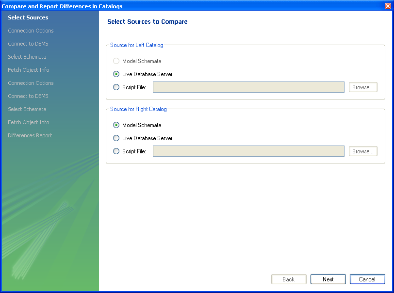
You then proceed through the wizard, providing connection information if accessing a live database. The wizard will then produce a catalog diff report showing the differences between the compared catalogs:
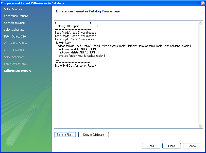
This chapter contains three short tutorials intended to familiarize you with the basics of MySQL Workbench. These tutorials show how MySQL Workbench can be used both to design and to document databases.
Creating a database from scratch is the focus of Section 16.6.8.2, “Using the Default Schema” and exploring the graphic design capabilities of MySQL Workbench is touched upon in Section 16.6.8.3, “Basic Modeling”. Both these tutorials show the database design capabilities of MySQL Workbench
Importing an SQL data definition script is probably the quickest way
to familiarize yourself with MySQL Workbench—this tutorial makes
use of the sakila database and emphasizes the use
of MySQL Workbench as a documentation tool. Examples taken from the
sakila database are used throughout the documentation so doing this
tutorial can be very helpful in understanding MySQL Workbench.
For this tutorial use the sakila database
script found in the Example Databases section
of the http://dev.mysql.com/doc/ page.
After downloading the file, extract it to a convenient location.
Open MySQL Workbench and find the menu option by first selecting
and then . Find
and import the sakila-schema.sql file. This
is the script that contains the data definition statements for the
sakila database. The file filter for the file
open dialog window defaults to *.sql so you
should only be able to view files with the sql
extension.
If the file was successfully imported, the application's status
bar reads, Import MySQL Create Script done. To
view the newly imported script, expand the Physical
Schemata section by double-clicking the arrow on the
left of the Physical Schemata title bar. Select
the tab labelled sakila.
Yo may also wish to remove the default schema tab,
mydb. Do this by selecting this tab and then
clicking the button on the upper right in
the Physical Schemata panel.
To view all the objects in the sakila schema,
you may need to expand the Physical Schemata
window. To do this move the mouse pointer anywhere over the gray
area that defines the lower edge of the Physical
Schemata window. Hold down the right mouse button and
move the mouse to adjust the size of the window.
Once you've expanded the window, all the objects in the
sakila database should be visible. Tables
appear at the top followed by views and then routines. There are
no routine groups in this schema, but you should see the
Routine Groups section and an Add
Group icon.
For a complete description of importing a MySQL create script see Section 16.6.7.9.1, “Reverse Engineering Using a Create Script”.
To create an EER diagram for the sakila
database, first add an EER diagram by double-clicking the
Add Diagram icon in the EER
Diagrams panel. This should create and open a new
EER Diagram.
The EER Diagram canvas is where object
modeling takes place. To add a table to the canvas, select the
Catalog tab in the middle panel on the
right side of the application. This should display any schemata
that appear in the MySQL Model tab.
Find the sakila schema and expand the view of its objects by clicking the button to the left of the schema name. Expand the tables list in the same way.
You can add tables to the EER canvas by picking them up from the
Catalog panel and placing them on the
canvas. Drop the address table and the
city table onto the canvas.
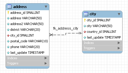
MySQL Workbench automatically discovers that
address.city_id has been defined as a foreign
key referencing the city.city_id field. Drop
the country table onto the canvas and
immediately you should see the relationship between the
country table and the city
table. ( See Figure 16.82, “The sakila EER Diagram” to view a PNG
file of all the relationships in the sakila
database.)
Choose the Properties tab of the panel on the
lower right and then click one of the tables on the canvas. This
displays the properties of the table in the
Properties window. While a table is selected
you can use the Properties window to change a
table's properties. For example, entering
#FF0000 for the color value will change the
color accent to red.
Changing the color of a table is a good way to identify a table
quickly—something that becomes more important as the
number of tables increases. Changing the color of a table is
also an easy way to identify a table in the Model
Navigator panel. This panel, the uppermost panel on
the left side of the screen, gives a bird's eye view of the
entire EER canvas.
Save your changes to a MySQL Workbench Models
file (mwb) by choosing from the
menu or by using the keyboard command
Ctrl S.
When you first open MySQL Workbench a default schema,
mydb appears as the left-most tab of the
Physical Schemata section of MySQL Workbench. You
can begin designing a database by using this default schema.

To change the name of the default schema, double-click the schema tab. This opens a schema editor window docked at the bottom of the application. To undock or redock this window, simply double-click anywhere in the editor title bar.
To rename the schema, use the text box labeled Name. Once you have renamed the schema a lightning bolt icon appears right aligned in the Name text box, indicating that other changes are pending. Click the Comments text area and a dialog box opens asking if you wish to rename all schema occurrences. Clicking ensures that your changes are propagated throughout the application. Add comments to the database and change the collation if you wish. Close the schema editor by clicking the button.
Create a new table by double-clicking the Add
Table icon in the Physical
Schemata panel. Doing this opens the table editor
docked at the bottom of the application. If you wish, you can
undock or dock this editor in exactly the same way as the schema
editor window.
Use the first tab of the table editor to change the name, collation, and engine. You may also add a comment.
Add columns to the new table by selecting the Columns tab. Use the default column name or enter a new name of your choosing. Use the Tab key to move to the next column and set the column's data type.
Altering the table by adding indexes or other features is also easily done using the table editor.
Additional objects such as views or routines can be added in the same way as tables.
Any objects you have created can be found in the Catalog palette on the right. To view these schema objects select the Catalog tab in the middle palette on the right. View all the objects by clicking the button to the left of the schema name.
Save your changes to a MySQL Workbench Models
file (mwb) by choosing from the
menu or by using the keyboard command
Ctrl S.
On the MySQL Model page, double-click the
Add Diagram icon. This creates and opens a
new EER Diagram.
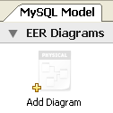
From an EER diagram page you can graphically design a database.
The tools in the vertical toolbar on the left of the
EER Diagram tab are used for designing an
EER diagram. Start by creating a table using the table tool. The
table tool is the rectangular grid in the middle of the vertical
toolbar. Mousing over it shows the message, Place a New
Table (T).
Clicking this tool changes the mouse pointer to a hand with a
rectangular grid. Create a table on the canvas by clicking
anywhere on the EER Diagram grid.
Right-click the table and choose from the pop-up menu. This opens the table editor, docked at the bottom of the application.
The table name defaults to table1. Change the
name by entering invoice into the
Name: text box. Notice that the name of the
tab in the table editor and the name of the table on the canvas,
both change to this new value.
Pressing Tab or Enter while
the cursor is in the table name text box, selects the
Columns tab of the table editor and creates
a default column named, idinvoice.
Pressing Tab or Enter again
sets the focus on the Datatype drop-down list
box with INT selected. Notice that a field
has been added to the table on the EER canvas.
Pressing Tab yet again and the focus shifts to
adding a second column. Add a Description and
a Customer_id column. When you are finished,
close the table editor, by clicking the
button on the top left of the table editor.
Select the table tool again and place another table on the
canvas. Name this table invoice_item. Next
click the 1:n Non-Identifying Relationship
tool.
First click the invoice_item table; notice
that a red border indicates that this table is selected. Next
click the invoice table. Doing this creates a
foreign key in the invoice_item table, the
table on the “many” side of the relationship. This
relationship between the two tables is shown graphically in
crow's foot notation.
Revert to the default mouse pointer by clicking the arrow at the
top of the vertical toolbar. Click on the
invoice_item table and select the
Foreign keys tab.
Click the Foreign key Name text box. The referenced table should show in the Referenced Table column and the appropriate column in the Referenced Column column.
To delete the relationship between two tables, click the line joining the tables and then press Ctrl Delete.
Experiment with the other tools on the vertical toolbar. Delete a relationship by selecting the eraser tool and clicking the line joining two tables. Create a view, add a text object, or add a layer.
Save your changes to a MySQL Workbench Models
file (MWB) by choosing from the
menu or by using the keyboard command
Ctrl S.
This chapter highlights the capabilities of MySQL Workbench as a
documentation tool using the sakila database as
an example. This is a sample database provided by MySQL and found in
the Example Databases section of the
http://dev.mysql.com/doc/ page. An EER diagram is an invaluable
aid to a quick understanding of any database. There is no need to
read through table definition statements; glancing at an EER diagram
can immediately indicate that various tables are related.
You can also see how tables are related; what the foreign keys are and what the nature of the relationship is.
Find below an EER digram showing all the tables in the
sakila database. This image was created using
the menu options ,
, .
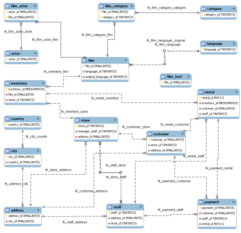
The object notation style used in
Figure 16.82, “The sakila EER Diagram” is Workbench (PKs
only). This notation only shows primary keys and no
other columns so it is especially useful where space is at a
premium. The relationship notation is the default, Crow's Foot.
As the connection lines show, each table is related to at least
one other table in the database (with the exception of the
film_text table). Some tables have two foreign
keys that relate to the same table. For example the
film table has two foreign keys that relate to
the language table, namely
fk_film_language_original and
fk_film_language. Where there is more than one
relationship between two tables, the connection lines run
concurrently.
Identifying and nonidentifying relationships are indicated by
solid and broken lines respectively. For example, the foreign key
category_id is part of the primary key in the
film_category table so its relationship to the
category table is drawn with a solid line. On
the other hand, in the city table, the foreign
key, country_id, is not part of the primary key
so the connection uses a broken line.
The printing options are used to create printouts of your EER Diagrams and are found under the menu. For creating documentation of your models see Section 16.6.5.1.5.1, “The DBDoc Model Reporting Dialog Window (Commercial Version)”.
The printing menu options are grayed if an EER Diagram is not active. The menu options are as follows:
Use this option to choose the paper size, orientation, and margins.
Use this option to send your EER Diagram directly to the printer. This option generates a preview before printing. From the preview you can adjust the scale of the view and also choose a multi-page view. Clicking the printer icon at the top left of this window, prints the currently selected EER Diagram. Close the print preview window if you need to adjust the placement of objects on the EER Diagram canvas.
Use this option to create a PDF file of your EER Diagram.
Use this option to create a PostScript file of your EER Diagram.
MySQL Workbench provides validation modules so that you can test your models before implementing them.
The validation plugins are accessed from the menu option. One plugin performs general validation for any Relational Database Management System (RDMS) and the other is MySQL-specific. Beneath these menu items are a number of specific validation tests. Running any one of these tests opens an output window docked at the bottom of the application. Warning messages are displayed on the left side of this window and the tests performed are displayed on the right.
The tasks performed by the validation modules are outlined in what follows.
The types of validation and examples that violate validation are listed in what follows:
Empty Content validation
A table with no columns
A routine or view with no SQL code defined
A routine group containing no routines
A table, view, or routine not referenced by at least one role
A user with no privileges
Objects such as tables that do not appear on at least one EER Diagram
Table Efficiency Validation
A table with no primary key
A primary key that does not use an integer-based data type
A foreign key that refers to a column with a different data type
Duplicated Identifiers Validation
Duplicate object names
Duplicate role or user names
Duplicate index or routine names
Consistency Validation
Use of the same column with columns of differing data types
Logic Validation
A foreign key that refers to a column other than the primary key in the source table
Any object that is object is either read- or write-only by role definition
Placeholder objects left over from reverse engineering
The types of MySQL-specific validation and examples that violate validation are listed in the following.
Integrity Violation
An object name longer than the maximum allowed
A foreign key defined for an engine type that doesn't support foreign keys (not yet implemented)
A view or routine that references a nonexistent table (not yet implemented)
A default value that does not match a column's data type
An invalid partitioning scheme
Syntax Violation
A routine, trigger, or view with incorrect SQL syntax
A reserved keyword used as an identifier
Use of an invalid character
This document aims to provide an overview of creating and modifying DBDoc Model Reporting templates, as used by MySQL Workbench.
The MySQL Workbench DBDoc Model Reporting system is based on the Google Template System. This document does not attempt to explain the Google Template System in detail. The Google document How To Use the Google Template System provides a useful overview of how the Google Template System works.
The templates employed by the DBDoc Model Reporting system are text
files that contain Markers. These text files are
processed by the template system built into MySQL Workbench, and the
markers replaced by actual data. The output files are then
generated. It is these output files, typically HTML or text, that
are then viewed by the user.
Markers can be of six types:
Template Include
Comment
Set delimiter
Pragma
Variable
Section start and Section end
The last two are the most commonly used in MySQL Workbench templates and these important markers will be briefly described in the following sections.
Variables
The use of variables in the templates is straightforward. Any variables denoted by markers in the template file, will be replaced by their corresponding data, prior to the output file being generated. The mapping between variables and their corresponding data is stored by MySQL Workbench in what is known as a Data Dictionary. In the data dictionary the variable name is the key and the variable's corresponding data is the value. The data dicionaries are built by MySQL Workbench and filled with the data contained in the model being processed.
By way of example, the following code snippet shows part of a template file:
Total number of Schemata: {{SCHEMA_COUNT}}In the generated output file the variable {{SCHEMA_COUNT}} will be replaced by the number of schemata in the model:
Total number of Schemata: 2
A variable can appear as many times as required in the template file.
Sections
Sections are used to perform iteration in the templates. When MySQL Workbench exchanges the variables in a section for data it will do so iteratively, using all data in the data dictionary in which the variable is defined. MySQL Workbench builds the data dictionaries according to the model currently being processed.
Again, this is best illustrated by example:
{{#SCHEMATA}} Schema: {{SCHEMA_NAME}} {{/SCHEMATA}}In the previous code snippet the section start is indicated by the
{{#SCHEMATA}}marker. The end of the section is indicated by the{{/SCHEMATA}}marker. When the template is processed, MySQL Workbench will note the section and iterate the section until the variable data for{{SCHEMA_NAME}}in the corresponding data dictionary is exhausted. For example, if the model being processed contains two schemata, the output for the section might resemble the following:Schema: Airlines Schema: Airports
That is, the model contains two schemata, Airlines and Airports.
Data Dictionaries
It is important to understand the relationship between sections and data dictionaries in more detail. In a data dictionary the key for a variable is the variable name, a marker. The variable value is the variable's data. The entry for a section in a data dictionary is different. For a section entry in a data dictionary, the key is the section name, the marker. However, the value associated with the key is a list of data dictionaries. In MySQL Workbench each section is usually associated with a data dictionary. You can think of a section as activating its associated dictionary (or dictionaries).
When a template is processed, data dictionaries are loaded in a hierarchical pattern, forming a tree of data dictionaries. This is illustrated by the following table.
| Data Dictionary | Loads Data Dictionary |
|---|---|
| MAIN | SCHEMATA |
| SCHEMATA | TABLES, COLUMNS (Detailed is true), FOREIGN_KEYS (Detailed is true), INDICES (Detailed is true) |
| TABLES | REL_LISTING, INDICES_LISTING, COLUMNS_LISTING, TABLE_COMMENT_LISTING, DDL_LISTING |
| COLUMNS_LISTING | COLUMNS (Detailed is false) |
| REL_LISTING | REL (Detailed is false) |
| INDICES_LISTING | INDICES (Detailed is false) |
The root of the tree is the main dictionary. Additional dictionaries are then loaded from the root to form the dictionary tree.
If a template has no sections in it, then any variables used in the template will be looked up in the main dictionary. If a variable is not found in the main dictionary (which can be thought of as associated with the default, or main, section) then no data will be generated in the output file for that marker.
Evaluation of variables
The tree structure of the data dictionaries is important when it comes to evaluation of variables. As variables are defined in data dictionaries, their associated value only has meaning when that particular data dictionary is active, and that means when the section associated with that data dictionary is active. When a variable lookup occurs, the system will check the data dictionary associated with the current section. If the variable value can be found there the replacement is made. However, if the variable's value is not found in the current data dictionary then the parent data dictionary will be checked for the variable's value and so on up the tree until the main data dictionary, or root, is reached.
This can best be illustrated by an example. Assume we want to display the names of all columns in a model. Consider the following template as an attempt to achieve this:
Report
------
Column Name: {{COLUMN_NAME}}
This template will produce no output, even for a model that contains
many columns. In this example the only data dictionary active is the
main dictionary. COLUMN_NAME however is stored in
the COLUMNS data dictionary, which is associated
with the COLUMNS section.
With this knowledge the template can be improved as follows:
Report
------
{{#COLUMNS}}
Column Name: {{COLUMN_NAME}}
{{/COLUMNS}}
This still does not produce output. Referring to the table
Data Dictionary
Hierarchy Tree explains why. The COLUMNS
data dictionary has the parent dictionary
COLUMNS_LISTING.
COLUMNS_LISTING has the parent
TABLES, which has the parent
SCHEMATA, whose parent is the main dictionary.
Remember that for a dictionary to be involved in variable lookup,
its associated section must currently be active.
So to achieve the desired output we would need the template to be something like the following:
Report
------
{{#SCHEMATA}}
{{#TABLES}}
{{#COLUMNS_LISTING}}
{{#COLUMNS}}
Column Name: {{COLUMN_NAME}}
{{/COLUMNS}}
{{/COLUMNS_LISTING}}
{{/TABLES}}
{{/SCHEMATA}}
The following template is the same, but with explanatory comments added:
Report
------
{{! Main dictionary active}}
{{#SCHEMATA}} {{! SCHEMATA dictionary active}}
{{#TABLES}} {{! TABLES dictionary active}}
{{#COLUMNS_LISTING}} {{! COLUMNS_LISTING dictionary active}}
{{#COLUMNS}} {{! COLUMNS dictionary active}}
Column Name: {{COLUMN_NAME}} {{! COLUMN_NAME variable is looked-up, and found, in COLUMNS data dictionary}}
{{/COLUMNS}}
{{/COLUMNS_LISTING}}
{{/TABLES}}
{{/SCHEMATA}}
Imagine now that for each column name displayed you also wanted to display its corresponding schema name, the template would look like this:
Report
------
{{#SCHEMATA}}
{{#TABLES}}
{{#COLUMNS_LISTING}}
{{#COLUMNS}}
Schema Name: {{SCHEMA_NAME}} Column Name: {{COLUMN_NAME}}
{{/COLUMNS}}
{{/COLUMNS_LISTING}}
{{/TABLES}}
{{/SCHEMATA}}
When variable lookup is performed for SCHEMA_NAME
the COLUMNS dictionary will be checked. As the
variable is not found there the parent dictionary will be checked,
COLUMNS_LISTING, and so on until the variable is
eventually found, where it is held, in the
SCHEMATA dictionary.
If there are multiple schemata in the model the outer section will
be iterated over a matching number of times, and
SCHEMA_NAME will accordingly have the correct
value on each iteration.
It's important to always consider which dictionary needs to be active (and which parents) for a variable to be evaluated correctly. In the following section you will find a table that helps you identify section requirements.
A list of supported markers follows. These markers can be used in any template, including custom templates.
| Marker text | Type | Data Dictionary defined in (if variable) or parent dictionary (if section) | Corresponding data |
|---|---|---|---|
| TITLE | Variable | MAIN | Title of the report |
| GENERATED | Variable | MAIN | Date and time that the report was generated |
| STYLE_NAME | Variable | MAIN | The name of the style selected in MySQL Workbench. This is typically used to load the corresponding CSS file, depending on the name of the style selected in MySQL Workbench. |
| SCHEMA_COUNT | Variable | MAIN | The total number of schemata in the model |
| PROJECT_TITLE | Variable | MAIN | Project title as set for the model in . |
| PROJECT_NAME | Variable | MAIN | Project name as set for the model in . |
| PROJECT_AUTHOR | Variable | MAIN | Project author as set for the model in . |
| PROJECT_VERSION | Variable | MAIN | Project version as set for the model in . |
| PROJECT_DESCRIPTION | Variable | MAIN | Project description as set for the model in . |
| PROJECT_CREATED | Variable | MAIN | Automatically set for the model project, but as displayed in . |
| PROJECT_CHANGED | Variable | MAIN | Automatically set for the model project, but as displayed in . |
| TOTAL_TABLE_COUNT | Variable | MAIN | Total number of tables in all schemata contained in the model. |
| TOTAL_COLUMN_COUNT | Variable | MAIN | Total number of columns in all tables in all schemata in the model. |
| TOTAL_INDEX_COUNT | Variable | MAIN | Total number of indexes in the model. |
| TOTAL_FK_COUNT | Variable | MAIN | Total number of foreign keys in the model. |
| SCHEMATA | Section | MAIN | Used to mark the start and end of a SCHEMATA section. The SCHEMATA data dictionary becomes active in this section. |
| SCHEMA_NAME | Variable | SCHEMATA | The name of a schema in the model |
| SCHEMA_ID | Variable | SCHEMATA | The ID of the schema |
| TABLE_COUNT | Variable | SCHEMATA | Total total number of tables in the current schema |
| COLUMN_COUNT | Variable | SCHEMATA | The total number of columns in the current schema |
| INDICES_COUNT | Variable | SCHEMATA | The total number of indexes in the current schema |
| FOREIGN_KEYS_COUNT | Variable | SCHEMATA | The total number of foreign keys in the current schema |
| TABLES | Section | SCHEMATA | Marks the start and end of a TABLES section. The TABLES data dictionary becomes active in this section. |
| TABLE_NAME | Variable | TABLES | The table name |
| TABLE_ID | Variable | TABLES | The table ID |
| COLUMNS_LISTING | Section | TABLES | Marks the start and end of a COLUMNS_LISTING section. The COLUMNS_LISTING data dictionary becomes active in this section. |
| COLUMNS | Section | COLUMNS_LISTING | Marks the start and end of a COLUMNS section. The COLUMNS data dictionary becomes active in this section. |
| COLUMN_KEY | Variable | COLUMNS | Whether the column is a primary key or not |
| COLUMN_NAME | Variable | COLUMNS | The name of the column |
| COLUMN_DATATYPE | Variable | COLUMNS | The data type of the column |
| COLUMN_NOTNULL | Variable | COLUMNS | Whether or not the column allows NULLs |
| COLUMN_DEFAULTVALUE | Variable | COLUMNS | The default value of entries in this column |
| COLUMN_COMMENT | Variable | COLUMNS | Any comment for this column |
| COLUMN_ID | Variable | COLUMNS | The ID of the column |
| COLUMN_KEY_PART | Variable | COLUMNS (if detailed) | The type of column key |
| COLUMN_NULLABLE | Variable | COLUMNS (if detailed) | Can the column contain NULLs |
| COLUMN_AUTO_INC | Variable | COLUMNS (if detailed) | Does the column auto-increment |
| COLUMN_CHARSET | Variable | COLUMNS (if detailed) | The character set used by the column |
| COLUMN_COLLATION | Variable | COLUMNS (if detailed) | The collation used by the column |
| COLUMN_IS_USERTYPE | Variable | COLUMNS (if detailed) | Whether or not the column is a user type |
| INDICES_LISTING | Section | TABLES | Marks the start and end of an INDICES_LISTING section. The INDICES_LISTING data dictionary becomes active in this section. |
| INDICES | Section | INDICES_LISTING | Marks the start and end of an INDICES section. The INDICES data dictionary becomes active in this section. |
| INDEX_NAME | Variable | INDICES | The name of the index |
| INDEX_PRIMARY | Variable | INDICES | Is this a primary index |
| INDEX_UNIQUE | Variable | INDICES | Is this a unique index |
| INDEX_TYPE | Variable | INDICES | The type of index e.g. PRIMARY |
| INDEX_KIND | Variable | INDICES | The kind of index |
| INDEX_COMMENT | Variable | INDICES | A comment for the index |
| INDEX_ID | Variable | INDICES | The ID of the index |
| INDEX_COLUMNS | Section | INDICES | Marks the start and end of an INDEX_COLUMNS section. The INDEX_COLUMNS data dictionary becomes active in this section. |
| INDEX_COLUMN_NAME | Variable | INDEX_COLUMNS | The index column name |
| INDEX_COLUMN_ORDER | Variable | INDEX_COLUMNS | The index column order e.g. ascending, descending |
| INDEX_COLUMN_COMMENT | Variable | INDEX_COLUMNS | A comment for the index column |
| INDEX_KEY_BLOCK_SIZE | Variable | INDEX_COLUMNS (if detailed) | Index key block size |
| REL_LISTING | Section | TABLES | Marks the start and end of a REL_LISTING section. The REL_LISTING data dictionary becomes active in this section. |
| REL | Section | REL_LISTING | Marks the start and end of a REL section. The REL data dictionary becomes active in this section. |
| REL_NAME | Variable | REL, FOREIGN_KEYS | Relationship name |
| REL_TYPE | Variable | REL, FOREIGN_KEYS | Relationship type |
| REL_PARENTTABLE | Variable | REL, FOREIGN_KEYS | Parent table of relationship |
| REL_CHILDTABLE | Variable | REL, FOREIGN_KEYS | Child table of relationship |
| REL_CARD | Variable | REL, FOREIGN_KEYS | Relationship card |
| FOREIGN_KEY_ID | Variable | REL | Foreign key ID |
| FOREIGN_KEYS | Section | SCHEMATA | Marks the start and end of a FOREIGN_KEYS section. The FOREIGN_KEYS data dictionary becomes active in this section. |
| FK_DELETE_RULE | Variable | FOREIGN_KEYS | Foreign key delete rule |
| FK_UPDATE_RULE | Variable | FOREIGN_KEYS | Foreign key update rule |
| FK_MANDATORY | Variable | FOREIGN_KEYS | Foreign key mandatory |
| TABLE_COMMENT_LISTING | Section | TABLES | Marks the start and end of a TABLE_COMMENT_LISTING section. The TABLE_COMMENT_LISTING data dictionary becomes active in this section. |
| TABLE_COMMENT | Variable | TABLE_COMMENT_LISTING | A comment for the table |
| DDL_LISTING | Section | TABLES | Marks the start and end of a DDL_LISTING section. The DDL_LISTING data dictionary becomes active in this section. |
| DDL_SCRIPT | Variable | DDL_LISTING | Display the DDL script of the currently active entity e..g. SCHEMATA, TABLES |
Using the table
The table shows which variables are defined in which sections. The variable should be used in its correct section, otherwise its value will not be displayed.
It should be remembered though that the data dictionaries used to perform the lookup form a hierarchical tree, so it is possible to use a variable defined in a parent section, in a child section.
In the simplest case a template consists of two files. A template
file, which has a .tpl extension, and a
special file info.xml. The
info.xml file has important metadata about
the template. A third file is optional, that is the preview image
file. This preview file provides a thumbnail image illustrating
the appearance of the generated report.
One of the easiest ways to create a custom template is to make a copy of any existing template.
For example, you make a custom template based on the Text
Basic. The following procedure demonstrates this.
First you need to make a copy of the template on which you are going to base your custom template. To do this navigate to the folder where the templates are stored. Assuming MySQL Workbench has been installed into the default location on Windows, this would be
C:\Program Files\MySQL\MySQL Workbench 5.0 SE\modules\data\wb_model_reporting.Then make a copy of the template folder you wish to base your new template on. In this case a copy of the
Text_Basic.tplfolder is made. The copy can be given any suitable name, for example,Custom_Basic.tpl.Now the
info.xmlfile needs to be edited, to reflect your custom template. The unedited file in this case is shown here:<?xml version="1.0"?> <data> <value type="object" struct-name="workbench.model.reporting.TemplateInfo" id="{BD6879ED-814C-4CA3-A869-9864F83B88DF}" struct-checksum="0xb46b524d"> <value type="string" key="description">A basic TEXT report listing schemata and objects.</value> <value type="string" key="name">HTML Basic Frame Report</value> <value type="list" content-type="object" content-struct-name="workbench.model.reporting.TemplateStyleInfo" key="styles"> <value type="object" struct-name="workbench.model.reporting.TemplateStyleInfo" id="{7550655C-CD4B-4EB1-8FAB-AAEE49B2261E}" struct-checksum="0xab08451b"> <value type="string" key="description">Designed to be viewed with a fixed sized font.</value> <value type="string" key="name">Fixed Size Font</value> <value type="string" key="previewImageFileName">preview_basic.png</value> <value type="string" key="styleTagValue">fixed</value> </value> </value> <value type="string" key="mainFileName">report.txt</value> </value> </data>Two objects are defined in the file. The
TemplateInfoobject and theTemplateStyleInfoobject. These objects contain information about the template that will be displayed in the DBDoc Model Reporting wizard main screen.The first thing you need to change are the object GUIDs that are used in the file. In this example there are two that need replacing:
id="{BD6879ED-814C-4CA3-A869-9864F83B88DF}" ... id="{7550655C-CD4B-4EB1-8FAB-AAEE49B2261E}"Generate two new GUIDS. This can be done using any suitable command-line tool. There are also free online tools that can be used to generate GUIDs. The
info.xmlfile should then be edited accordingly.Edit the textual information for the
TemplateInfoandTemplateStyleInfoobjects to reflect the purpose of the custom template.The modified file will now look something like the following:
<?xml version="1.0"?> <data> <value type="object" struct-name="workbench.model.reporting.TemplateInfo" id="{cac9ba3f-ee2a-49f0-b5f6-32580fab1640}" struct-checksum="0xb46b524d"> <value type="string" key="description">Custom basic TEXT report listing schemata and objects.</value> <value type="string" key="name">Custom Basic text report</value> <value type="list" content-type="object" content-struct-name="workbench.model.reporting.TemplateStyleInfo" key="styles"> <value type="object" struct-name="workbench.model.reporting.TemplateStyleInfo" id="{39e3b767-a832-4016-8753-b4cb93aa2dd6}" struct-checksum="0xab08451b"> <value type="string" key="description">Designed to be viewed with a fixed sized font.</value> <value type="string" key="name">Fixed Size Font</value> <value type="string" key="previewImageFileName">preview_basic.png</value> <value type="string" key="styleTagValue">fixed</value> </value> </value> <value type="string" key="mainFileName">custom_report.txt</value> </value> </data>The next step is to create the new template file. Again this may best be achieved, depending on your requirements, by editing an existing template. In this example the template file
report.txt.tplis shown here:+--------------------------------------------+ | MySQL Workbench Report | +--------------------------------------------+ Total number of Schemata: {{SCHEMA_COUNT}} ============================================= {{#SCHEMATA}} {{SCHEMA_NR}}. Schema: {{SCHEMA_NAME}} ---------------------------------------------- ## Tables ({{TABLE_COUNT}}) ## {{#TABLES}}{{TABLE_NR_FMT}}. Table: {{TABLE_NAME}} {{#COLUMNS_LISTING}}## Columns ## Key Column Name Datatype Not Null Default Comment {{#COLUMNS}}{{COLUMN_KEY}}{{COLUMN_NAME}}{{COLUMN_DATATYPE}} » {{COLUMN_NOTNULL}}{{COLUMN_DEFAULTVALUE}}{{COLUMN_COMMENT}} {{/COLUMNS}}{{/COLUMNS_LISTING}} {{#INDICES_LISTING}}## Indices ## Index Name Columns Primary Unique Type Kind Comment {{#INDICES}}{{INDEX_NAME}}{{#INDICES_COLUMNS}}{{INDEX_COLUMN_NAME}} » {{INDEX_COLUMN_ORDER}}{{INDEX_COLUMN_COMMENT}}{{/INDICES_COLUMNS}} » {{INDEX_PRIMARY}}{{INDEX_UNIQUE}}{{INDEX_TYPE}}{{INDEX_KIND}}{{INDEX_COMMENT}} {{/INDICES}}{{/INDICES_LISTING}} {{#REL_LISTING}}## Relationships ## Relationship Name Relationship Type Parent Table Child Table Cardinality {{#REL}}{{REL_NAME}}{{REL_TYPE}}{{REL_PARENTTABLE}}{{REL_CHILDTABLE}}{{REL_CARD}} {{/REL}}{{/REL_LISTING}} --------------------------------------------- {{/TABLES}} {{/SCHEMATA}} ============================================= End of MySQL Workbench ReportThis template shows details for all schemata in the model.
The above template file can be edited in any way you like, with new markers being added, and existing markers being removed as required. For the custom template example you might want to create a much simpler template. Such as the one following:
+--------------------------------------------+ | MySQL Workbench Custom Report | +--------------------------------------------+ Total number of Schemata: {{SCHEMA_COUNT}} ============================================= {{#SCHEMATA}} Schema Name: {{SCHEMA_NAME}} ---------------------------------------------- ## Tables ({{TABLE_COUNT}}) ## {{#TABLES}} Table Name: {{TABLE_NAME}} {{/TABLES}} {{/SCHEMATA}} Report Generated On: {{GENERATED}} ============================================= End of MySQL Workbench Custom ReportThis simplified report just lists the schemata and the tables in a model. The date and time the report was generated will also be displayed as a result of the use of the
{{GENERATED}}variable.The custom template can then be tested. Start MySQL Workbench, load the model to generate the report for, select the , menu item. Then select the new custom template from the list of available templates, select an output directory and then click to generate the report. Finally, navigate to the output directory to view the finished report.
Since version 5.2.6 MySQL Workbench has included functionality for managing server instances. A server instance is created to provide a way of connecting to a server to be managed. The first step then is to create a server instance if none exists, or to work with an existing server instance.
MySQL Workbench also provides functionality to administer and configure a server using these server instances. Thus, the Server Administrator functionality can be broadly grouped into two main areas:
Creating and managing server instances
Administration and configuration functions using a server instance
In the Workspace section of the Home screen is an area for Server Administration tasks. This section of the Workspace has the following action items:
Server Administration
Server Administration (icon)
New Server Instance
Manage Data Import/Export
Manage Security
Manage Server Instances
Each of these action items is described in the following sections.
The purpose of this action item is to allow you to quickly connect to a predefined server instance, and carry out administration functions on the associated server. Clicking this item launches the Server Administration dialog, from which you can select the server instance you wish to connect to. A new Admin tab will be launched, which displays the Server Status and Configuration.
Server Administration (icon)
If you have already created server instances, then you can most quickly launch these by clicking the icon for the Server Instance you wish to access. A new Admin tab will be launched, which displays Server Status and Configuration.
For further details see the section Section 16.7.7, “Server Administration and Configuration”.
This action item enables you to create a new server instance. A server instance is primarily a combination of connection and configuration details for a specific server that you wish to manage. When you click this item a wizard is launched that allows you to specify the connection and various other configuration parameters. After completion of the wizard, a new Admin tab is launched, which displays Server Status and Configuration.
For further details see the section Section 16.7.6.1, “New Server Instance Wizard”.
The purpose of this action item is to allow you to create a dump file from a database, or restore data from a file to a live database. Clicking this item launches the Import/Export MySQL Data wizard. This enables you to select a server instance to connect to.
For further details see the section Section 16.7.7.6, “Data Dump tab”.
The purpose of this action item is to take you quickly to the screen that enables you to manage user accounts. It simply launches an Admin page and locates you on the Accounts tab.
For further details see the section Section 16.7.7.3, “Accounts tab”.
Clicking this action item launches the Manage Server Instances dialog. Within this dialog you can change the configuration of existing server instances, or create a new server instance.
This topic is discussed in more depth in the section Section 16.7.6, “Creating and Managing Server Instances”.
Server instances can be created and managed from the Home page. As mentioned in the previous section, there are several ways new server instances can be created:
By clicking the New Server Instance action item from the Server Administration section of the Home screen. This launches the Create a new server instance wizard.
By clicking the Manage Server Instances action item from the Server Administration section of the Home screen. This launches the Manage Server Instances dialog, from within which a new server instance can be created.
Each of these two options is now described in turn.
Clicking the New Server Instance action item launches the Create a new server instance wizard. The wizard provides a step-by-step approach to creating a new server instance. This is most suitable for beginners. Once some familiarity is achieved with the various settings and parameters required, a new instance can also be quickly created from the Manage Server Instances dialog discussed later.
The steps presented in the wizard are as follows:
Specify host machine
Operating system
Host SSH Connection
Test Settings
Database Connection
Test DB Connection
MySQL Config File
Specify Commands
Complete Setup
Results
Specify host machine
On this page you can select Localhost if you intend to manage a server on your local machine. Or you can select Remote Host. In this latter case you will need to provide the IP address or the network name of the remote server. Click to continue.
Operating system
On this page you simply select the operating system that applies to your server. You should also ensure that the option you select from the drop-down listbox also reflects your MySQL Server version and installation type, for example, Windows (MySQL 5.1 Installer Package).
Host SSH Connection
If you specified a Remote Host on the Specify Host Machine page, you will be presented with the Host SSH Connection page. This page enables you to enable SSH for the login to the server instance. This facility enables you to create a secure connection to remotely administer and configure the server instance. You need to enter the username and password of the account that will be used to log in to the server for administration and configuration activities. If you do not enter a password, you will be prompted for the password when the connection is established by MySQL Workbench. You can optionally specify the path to your SSH key for use with the server, rather than enter a username and password.
This connection is to allow remote administration and configuration of the MySQL Server itself. It is not the same as the connection used to connect to a server for general database manipulation.
If managing a remote server, you will need to use an SSH connection type if you wish to start or stop the server or edit its configuration file. Other administrative functions do not require an SSH connection type.
Test Settings
On the next page your settings will be tested. The wizard will report back the results of attempting to connect to the server. If an error occurs you will be directed to view the logs, which can be done by clicking the button.
Database Connection
This page enables you to select a connection to a specific database. The settings entered previously have been concerned with the connection to the server required for admnistrative purposes. This page is concerned with connection to a specific database. You can either launch the Manage DB Connections dialog or select a pre-existing connection from a drop-down listbox. The former is most useful if you have not created any connections. If you do need to create a connection at this point then refer to Section 16.5.6, “Manage DB Connections Dialog”. Once a connection has been selected click to continue.
Test DB Connection
On this page your database connection will be tested and results displayed. If an error occurred you will be directed to view the logs. This can be achieved by clicking the button.
MySQL Config File
For MySQL Server configuration information to be fetched and displayed in MySQL Workbench, the location of the MySQL Server configuration file needs to be known. The wizard will be able to determine the most likely location of the configuration file, based on the selection made on the Operating System page of the wizard. However, it is possible to test that this information is correct by clicking the and buttons. The wizard will then report if the configuration file and server configuration section can in fact be accessed. It is also possible to manually enter the location of the configuration file, and the section pertaining to MySQL Server data, but again these manually entered values should be tested using the buttons provided. Click the button to continue.
Specify Commands
This page enables you to set the commands required to start, stop and check the status of the running server instance. These felds will have defaults set based on the option selected on the Operating System page of the wizard. It is possible to customize the commands if required, but the defaults will be suitable in most cases. Click to continue.
Complete Setup
On this page you finally assign a name to the server instance. This name is used in various parts of the GUI to allow you to recall this instance. After setting a suitable name, click to continue.
Results
This is the final page of the wizard. It simply summarizes the settings you have selected. If everything looks good click to create the server instance and exit the wizard.
The Manage Server Instances dialog enables you to create, delete and manage server instances. The Connection tab of the wizard enables you to select a predefined connection to connect with a server to be managed. In addition, it is also possible to connect to a remote server using an SSH connection.
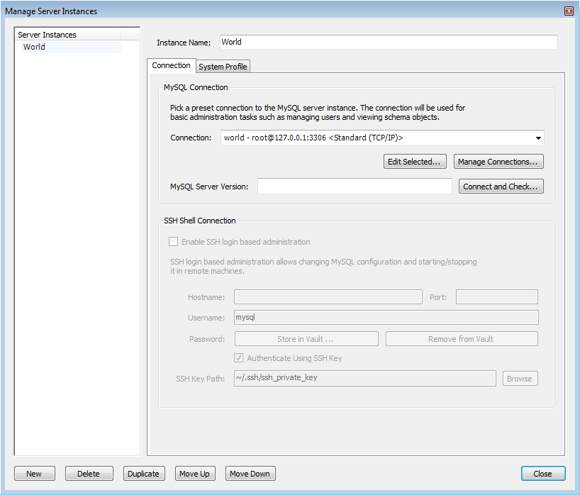
The System Profile tab of the wizard allows you to specify server specific information. This is primarily achieved through selecting a Profile Template. A Profile Template contains standard information used in managing the server instance. The following Profile Templates are available:
Fedora Linux (MySQL Package)
Fedora Linux (Vendor Package)
FreeBSD (MySQL Package)
Generic Linux (MySQL tar package)
Mac OS X (MySQL Package)
OpenSolaris (MySQL Package)
RHEL (MySQL Package)
SLES (MySQL Package)
Ubuntu Linux (MySQL Package)
Ubuntu Linux (Vendor Package)
Windows (MySQL 5.0 Installer Package)
Windows (MySQL 5.1 Installer Package)
Windows (MySQL zip package)
Custom
Once a profile is selected a number of default parameters will
be set, including commands used to start and stop MySQL,
commands to check server status and the location of the
my.ini configuration file.
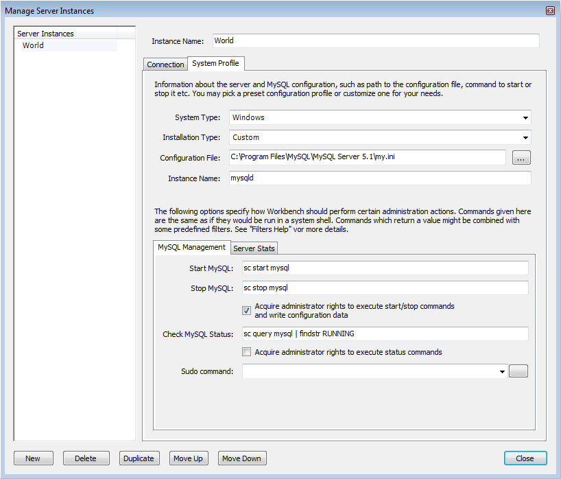
After an instance has been created it can be launched by double-clicking its icon in the Server Administration panel of the Home page. This creates an Admin page. The Admin page has two main panels, the Server Status panel, and the Configuration panel. The Configuration panel features multiple tabs: Startup, Configuration, Accounts, Connections, Variables, Data Dump, and Logs.
The functionality included in MySQL Workbench for administering servers is similar to that formerly provided by MySQL Administrator. The Administrator functionality in MySQL Workbench is grouped into several tabs:
Startup: Enables you to start and stop the MySQL server, and view the startup message log.
Configuration: Enables you to view and edit the MySQL Configuration file (
my.ini) using GUI controls.Accounts: Enables you to create user accounts and assign roles and privileges.
Connections: Displays connections to MySQL Server.
Variables: Displays server and status variables.
Data Dump: Import and export of data.
Logs: Displays server log file entries.
The Administrator also displays system and server status. System status displayed includes:
CPU utilization
Memory usage
Connection Health
For server health the following are displayed:
Connection Usage
Traffic
Query Cache Hit Rate
Key Efficiency

The Startup tab has several purposes:
Displaying database server status.
Start up and shut down the server.
Displaying the Startup Message log.
The ability to select whether the server starts up when the system starts up.
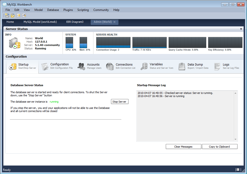
The configuration tab enables you to edit the
my.ini configuration file through selecting
checkboxes and other GUI controls. This tab also features a
number of sub-tabs, which provide access to various sub-sections
within the configuration file. The sub-tabs are:
General
MyISAM Parameters
InnoDB Parameters
Performance
Log Files
Replication
Networking
Security
Advanced

The Accounts tab has two sub-tabs:
Server Access Management
Schema
      Privileges
Server Access Management enables you to list existing user accounts. You can also add and delete accounts. You can allocate administrative roles and also set account limits.
Schema Privileges enables you to set specific privileges on a user basis.
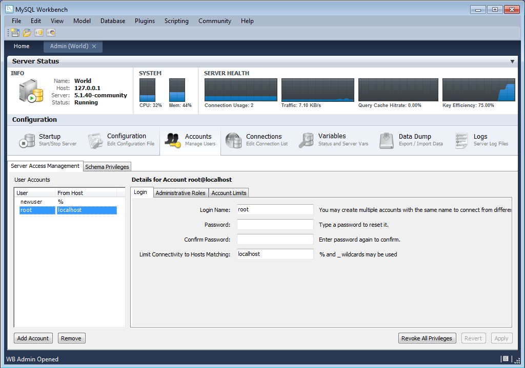
In the current version of MySQL Workbench it is not possible to manage privileges below the schema level. For example, it is not possible to view or manage grants at the table, column, or procedure level. Support for this feature is however planned for MySQL Workbench 6.0.
To aid in the assignment of privileges to MySQL Server users,
MySQL Workbench introduces the concept of Administrative Roles.
Roles are a quick way of granting a number of privileges to a
user, based on the work the user needs to carry out on the
server. It is also possible to assign multiple roles to a
user. To assign roles, click the User Account you wish to
modify, then click the Administrative
Roles tab. Then click the checkboxes according to
the roles you wish to allocate to the user. Note once you
select a role to a user you will see the accumulated
privileges in the Global Privileges Assigned to
User panel. For example, if you select the role
BackupAdmin the privileges granted would
include EVENT, LOCK
TABLES, SELECT, SHOW
DATABASES. Then if you additionally select the role
of ReplicationAdmin, the list of privileges
will be expanded to also include REPLICATION
CLIENT, REPLICATION SLAVE and
SUPER.
The roles available are:
DBA: Grants all privileges
MaintenanceAdmin: Grants privileges to maintain server
ProcessAdmin: Grants privileges to monitor and kill user processes
UserAdmin: Grants privileges to create users and reset passwords
SecurityAdmin: Grants privileges to manage logins and grant and revoke server
MonitorAdmin: Grants privileges to monitor server
DBManager: Grants privileges to manage databases
DBDesigner: Grants privileges to create and reverse engineer any database schema
ReplicationAdmin: Grants privileges to set up and manage replication
BackupAdmin: Grants privileges required to backup databases
This tab lists all current connections to the monitored server.
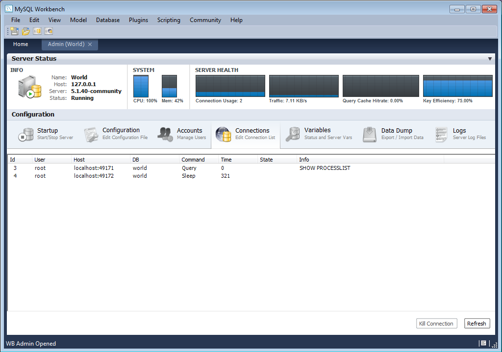
The Variables tab displays a list of all server and status variables.
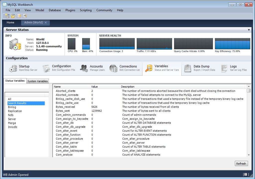
The Import/Export Server Data tab enables you to create a dump file, or restore data from a dump file. Clicking the Import/Export Server Data action item launches a new Admin screen, at the Data Dump tab.
Within the Data Dump tab are three further tabbed windows:
Export to Disk
Import from Disk
Advanced Options
This tab enables you to select the schema and tables you wish to export. You also have the option to export tables to their own files, or all tables to a single file. Exporting tables to individual files enables you to restore on a per-table basis.

This tab enables you to import a previously exported project. You can select to import a project where tables were stored in individual files, in which case you will also be able to select which of these tables you wish to import. You can also simply import a project saved to a single file.
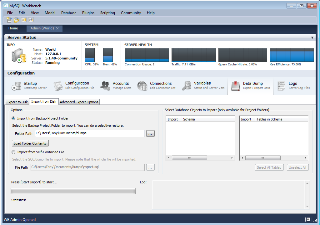
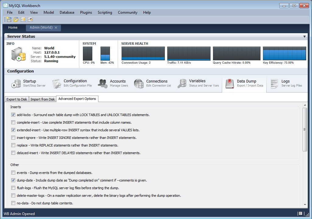
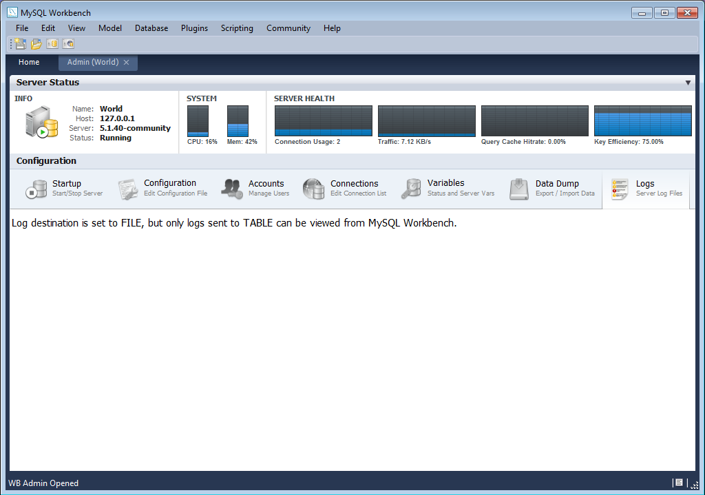
MySQL Workbench provides an extension and scripting system that allows
the developer to extend MySQL Workbench according to requirements. While
the core of MySQL Workbench is developed using C++, it is possible to
harness this core functionality using both the Lua and Python
scripting languages. MySQL Workbench also provides access to a
cross-platform GUI library, mforms, which enables
the creation of extensions that feature a graphical user interface.
The extension capabilities enable the following:
Automate common tasks
Extend the Workbench user-interface
Create plugins (code which can be invoked from the Workbench menu system)
Manipulate schemata
Create custom Workbench features
The GRT, or Generic RunTime, is the internal system used by Workbench to hold model document data. It is also the mechanism by which Workbench can interact with Modules and Plugins. Workbench model data, such as diagrams, schemata and tables, is stored in a hierarchy of objects that can be accessed by any plugin. The data is represented using standard data types: integers, doubles, strings, dicts, lists and objects.
The GRT can be accessed using external scripting languages such as Lua and Python. Awareness is required of how the GRT data types map into the scripting language. In Python, for example, the GRT data types integers, doubles and strings are seen as corresponding Python data types. Lists and dicts are kept in their internal representation, but can however generally be treated as Python lists and dicts, and accessed in the usual way. Objects contain data fields and methods, but the GRT only recognizes objects from a pre-registered class hierarchy.
It is possible to fully examine the classes contained within the
GRT using the Workbench Scripting Shell. Note that dots in class names are changed to
underscores in their Python counterparts. For example,
db.mysql.Table becomes
db_mysql_Table in Python.
The Application Objects Tree (GRT Tree)
As mentioned previously the Workbench document data is stored in an object hierarchy. This hierarchy is known as the GRT Tree. The GRT Tree can be accessed and modified from supported external scripting languages such as Python. Care should be taken when modifiying the GRT Tree, in case a mistake leads to corruption of the document. Backups should be made before manipulating the tree. Read-only access to the tree is the safest approach, and is sufficient in most cases.
The main nodes in the Application Object Tree
| Node | Description |
|---|---|
| wb.registry | Application data such as plugin registry, list of editors, and options. |
| wb.customData | A generic dictionary for data you can use to store your own data. This dictionary is saved and reloaded with Workbench and is global (not document specific). |
| wb.options | Contains some default options that are used by Workbench |
| wb.rdbmsMgmt | Internal registry of supported RDBMS modules, known data types. |
| wb.doc | The currently loaded model document. |
| wb.doc.physicalModels[0] | The currently loaded model object, containing the database catalog and diagrams. |
| wb.doc.physicalModels[0].catalog | The database catalog for the model. Contains the list of schemata. |
| wb.doc.physicalModels[0]catalog.schemata | List of schemata in the model. Individual schema can be accessed as a list: schemata[0], schemata[1] ... |
| wb.doc.physicalModels[0].catalog.schemata[0].tables (.views, .routines, ...) | Lists of tables, views, routines in the schema. |
| wb.doc.physicalModels[0].diagrams | List of EER diagrams in the model |
| wb.doc.physicalModels[0].diagrams[0].figures (.layers, .connections, ...) | List of figures, layers, connections (relationships) in the diagram. |
In the GRT Modules are libraries containing a list of functions that are exported for use by code in other modules, scripts or Workbench itself. Modules can currently be written in C++, Lua or Python, but the data types used for arguments and the return value must be GRT types.
GRT modules are similar to Python modules. They are however
imported from the built-in grt module, instead
of directly from an external file. The list of modules loaded into
the grt module is obtained
grt.modules. Modules can be imported in Python
using statements such as from grt.modules import
WbModel.
To export functions as a module from Python code you need to carry out the following:
The source file must be located in the user modules folder. This path is displayed in the Workbench Scripting Shell with the label Looking for user plugins in.... It is also possible to install the file using the main menu item , .
The source file name must have the extension
_grt.py, for example,my_module_grt.py.Some module metadata needs to be defined. This can be done using the
DefineModulefunction from the wb module:from wb import * ModuleInfo = DefineModule(name='MyModule', author='Your Name', version='1.0')
Functions to be exported require their signature to be declared. This is achieved using the export decorator in the previously created ModuleInfo object:
@ModuleInfo.export(grt.INT, grt.STRING)
def checkString(s):
   ...
Note, for the export statement, the return type is listed first, followed by the input parameter types. These types are specified as GRT typenames. The typenames that can be used are as follows:
grt.INT: Integer values. Also used for boolean values.
grt.DOUBLE: Floating-point numeric values.
grt.STRING: UTF-8 or ASCII string data.
grt.DICT: A key/value dictionary item. Keys must be strings.
grt.LIST: A list of other values. It is possible to specify the type of the contents as a tuple in the form
(grt.LIST, <type-or-class>). For example, (grt.LIST, grt.STRING) for a list of strings. For a list of table objects the following would be specified:(grt.LIST, grt.classes.db_table).grt.OBJECT: An instance of a GRT object or a GRT class object, from grt.classes.
Note these types are defined in the
grtmodule, which must first be imported before they can be used.
The following code snippet illustrates declaring a module that exports a single function:
from wb import *
import grt
ModuleInfo = DefineModule(name='MyModule', author="your name", version='1.0')
@ModuleInfo.export(grt.DOUBLE, grt.STRING, (grt.LIST, grt.DOUBLE))
def printListSum(message, doubleList):
   sum = 0
   for d in doubleList:
      sum = sum + d
   print message, sum
   return sum
Plugins are special Modules that are exposed to the user through the Workbench GUI. This is typically done using the main menu, or the context-sensitive menu. Much of the MySQL Workbench functionality is implemented using plugins, for example, tabel, view, and routine editors are native C++ plugins, as are the forward and reverse engineering wizards. The Administrator facility in MySQL Workbench is implemented entirely as a plugin in Python.
A plugin can be a simple function that performs some action on an
input, and ends without further interaction with the user.
Examples of this include auto-arranging a diagram, or making batch
changes to objects. To create a simple plugin, the function needs
to be located in a module and then declare it as a plugin using
the plugin decorator of the
ModuleInfo object.
Plugins can have an indefinite runtime, such as when they are driven by the user through a graphical user interface. This is the case for the various object editors and wizards within MySQL Workbench. Although this latter type of plugin will need to be declared in the usual way, only the entry point of the plugin will need to be executed in the plugin function, as most of the additional functionality will be invoked as a result of the user interacting with the GUI.
The syntax for declaring a plugin is as follows:
@ModuleInfo.plugin(plugin_name, caption, [input], [groups], [pluginMenu])
These parameters are defined as follows:
plugin_name: A unique name for the plugin. It may only contain alphanumeric characters, dots, and underscores.
caption: A caption to use for the plugin in menus.
input: An optional list of input arguments.
groups: Optional list of groups the plugin belongs to. Recognized values are:
Overview/Utility: The menu in the Model Overview.Model/Utility: The menu for diagram objects.Menu/<category>: The menu in the main menu.
pluginMenu: Optional name of a submenu in the Plugins menu where the plugin should appear. For example, , , . This is equivalent to adding a
Menu/<category>in the groups list.
MySQL Workbench is implemented with a C++ core back-end, and a native
front-end for each supported platform. Currently the front-end is
implemented with Windows Forms on Microsoft Windows, GTK+ on
Linux, and Cocoa on Mac OS X. This approach allows the application
to have a native look and feel, while reducing the amount of work
required to maintain the project. However, the GUI functionality
required by MySQL Workbench can be met by a subset of graphical
operations. These are implemented in a cross-platform GUI library,
MForms. This further reduces the development effort, as plugin
developers can use MForms, rather than having to write front-end
specific code for each supported platform. This also helps
consistency of operation across all platforms. MForms is coded in
C++, but provides a Python interface. To use it the Python code
needs to import the mforms module.
MForms Containers
Given problems of using an absolute co-ordinate system across different platforms, MForms employs containers that perform automatic layout. The basic containers that MForms provides include:
Form: A top-level window which can contain a single control, usually another container. The window will be sized automatically to fit its contents, but can also be sized statically.
Box: This is a container that can be filled with one or more controls in a vertical or horizontal layout. Each child control can be set to use either the minimum of required space, or fill the box in the direction of the layout. In the direction perpendicular to the layout, for example vertical in a horizontal layout, the smallest possible size that can accommodate all child controls will be employed. So, in this example, the smallest height possible to accommodate the controls would be used.
Table: This is a container that can organize one or more controls in a grid. The number of rows and columns in the table, and the location of controls within the grid, can be set by the developer.
ScrollView: This is a container that can contain a single child control, and will add scrollbars if the contents do not fit the available space.
The Workbench Scripting Shell provides a means for entering and executing scripts. Through the use of the scripting shell, MySQL Workbench can support new behavior and data sources using code written in Lua and Python. The shell can also be used to explore the current Workbench GRT (Generic Runtime) facilities.
The scripting shell is not only useful for expanding MySQL Workbench. You can use a script file from the scripting shell command line to perform repetitive tasks programmatically.
The default development language is Lua, a
lightweight scripting language expressly designed for extending
applications. For more information about this language see
lua.org.
The Python language is also supported, further details of this language can be found from the official Python site.
The programming language to be used in Workbench Scripting Shell can be selected from the General tab of the Workbench Preferences dialog. The Workbench Preferences dialog can be displayed using the main menu item , .
To open the Workbench Scripting Shell, select , from the main menu. You can also open the Workbench Scripting Shell using the Ctrl+F3 key combination on Windows and Linux, cmd F3 on Mac OS X, or by clicking the shell button above the EER diagram navigator. The Workbench Scripting Shell will then open in a new dialog.
The following screenshot shows the Workbench Scripting Shell dialog:
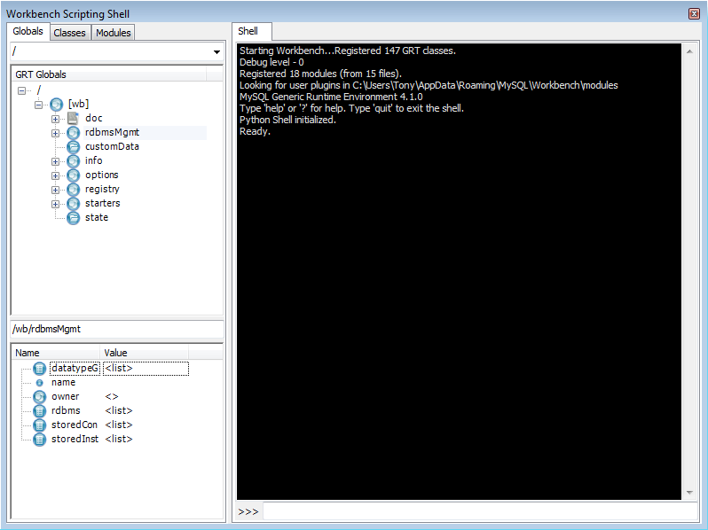
The Workbench Scripting Shell is primarily used for running Lua or Python scripts
or typing commands in these languages directly. However, you can
also use it to access the Workbench Scripting Shell Scripting Library functions and
global functions and objects. To see the available commands type
“?”. You can also cut and paste
text to and from the shell window.
While individual commands can be entered into the shell, it is also possible to run a longer script, stored in an external file, using the main menu option , . When scripts are run outside of the shell, to see the output use the main menu item , .
It is also possible to run script files directly from the shell. For details on running script files, type ? run at the Workbench Scripting Shell prompt. The following message is displayed:
  Shell Command - shell.run
  -------------------------
  Load and execute a lua script file.
  run filename
  Parameters:
  filename       File that should be loaded and executed.
  Examples:
  run scripts/test.lua
  Runs the script scripts/test.lua.
Within the Workbench Scripting Shell, on the left side panel, are three tabs: Globals, Classes, and Modules. Discussion of these additional tabs follows.
The Workbench Scripting Shell features the Globals, Classes and Modules tabs, in addition to the main Shell tab.
The Globals Tab
At the top of the window is a drop down list box that is used to select the starting point, or root, of the GRT Globals tree displayed beneath it. By default this starting point is the root of the tree, that is, '/'. The GRT Globals tree can be expanded and collapsed as required. The GRT Globals tree is the structure in which MySQL Workbench stores document data. Clicking any item will result in its name and value being displayed in the panel below the tree.
The Classes Tab
A class is a user-defined data type formed by
combining primitive data types: integers, doubles, strings,
dicts, lists, and objects. This tab shows the definitions of the
classes used by the objects in the Modules
tab. Clicking a class causes a brief description of the class to
be displayed in a panel below the classes explorer.
When the Classes tab is selected, the dropdown listbox lists the following items:
Group by Name: Group by the object name
Group by Hierarchy: Group by inheritance
Group by Package: Group by functionality
The default view for this tab is Group By Name. This view simply shows all the different objects arranged alphabetically. Click the icon or double-click a package to show the properties of the struct.
If you switch to the hierarchical view you will see
GrtObject: the parent object from which all
other objects are derived.
The Modules Tab
The Modules tab enables you to browse the MySQL Workbench installed modules and their functions. Clicking a module within the explorer causes its details to be displayed in a panel below the explorer. This facility is useful for exploring the available modules, and their supported functions. It is also a way to check if custom modules have been correctly installed.
The purpose of this tutorial is to show you how to extend MySQL Workbench by creating a plugin.
The sample plugin
EER Diagrams are useful for visualizing complex database schemata.
They are often created for existing databases, to clarify their
purpose or document them. MySQL Workbench provides facilities for
reverse engineering existing databases, and then creating an EER
Diagram automatically. In this case relationship lines between
foreign keys in the table will automatically be drawn. This
graphical representation makes the relationships between the tables
much easier to understand. However, one of the most popular storage
engines for MySQL, MyISAM, does not include support for foreign
keys. This means that MyISAM tables that are reverse engineered will
not automatically have the relationship lines drawn between tables,
making the database harder to understand. The plugin that will be
created in this tutorial gets around this problem by using the fact
that a naming convention is very often used for foreign keys:
tablename_primarykeyname. Using this convention,
foreign keys can automatically be created after a database is
reverse engineered, which will result in relationship lines being
drawn in the EER diagram.
Algorithm
The basic algorithm for this task would be as follows:
for each table in the schema
   for each column in the table
      look for another table whose name and primary key name match the current column name
      if such a table is found, add a foreign key referencing it
As iterating the complete table list to find a match can be slow for models with a large number of tables, it is necessary to optimize by pre-computing all possible foreign key names in a given schema.
import grt

def auto_create_fks(schema):
   fk_name_format = "%(table)s_%(pk)s"
   possible_fks = {}
   # create the list of possible foreign keys from the list of tables
   for table in schema.tables:
      if table.primaryKey:
         format_args = {'table':table.name, 'pk':table.primaryKey.name}
         fkname = fk_name_format % format_args
         possible_fks[fkname] = table

   # go through all tables in schema, this time to find columns that may be a fk
   for table in schema.tables:
      for column in table.columns:
         if possible_fks.has_key(column.name):
            ref_table = possible_fks[column.name]
            if ref_table.primaryKey.formattedType != column.type:
               continue
            fk = table.createForeignKey(column.name+"_fk")
            fk.referencedTable = ref_table
            fk.columns.append(column)
            fk.referencedColumn.append(ref_table.primaryKey)
            print "Created foreign key %s from %s.%s to %s.%s" % (fk.name, table.name, column.name, ref_table.name, ref_table.primaryKey.name)

auto_create_fks(grt.root.wb.doc.physicalModels[0].catalog.schemata[0])
Creating a Plugin from a Script
To create a plugin from an arbitrary script, it is first necessary to make the file a module, and export the required function from it. It is then necessary to declare the module as a plugin, and specify the return type and input arguments.
from wb import *
import grt

ModuleInfo = DefineModule(name="AutoFK", author="John Doe", version="1.0")

@ModuleInfo.plugin("sample.createGuessedForeignKeys", caption="Create Foreign Keys from ColumnNames",
input=[wbinputs.objectOfClass("db.mysql.schema")], groups=["Overview/Utility"])
@ModuleInfo.export(grt.INT, grt.classes.db_mysql_Schema)
def auto_create_fks(schema):
   ...
With the addition of the above code, the
auto_create_fks() function is exported and will
be added to the schema context menu in the model overview. When
invoked it will receive the currently selected schema as its input.
On Mac OS X modifier key is cmd, on other platforms it is Ctrl.
File Menu
| Function | Context | Keyboard Shortcut |
|---|---|---|
| New Model | All | Modifier+N |
| Open Model | All | Modifier+O |
| Open SQL Script | SQL Editor | Modifier+Shift+O |
| Close Tab | All | Modifier+W |
| Save Model | Model | Modifier+S |
| Save Script | SQL Editor | Modifier+S |
| Save Model As | Model | Modifier+Shift+S |
| Save Script As | SQL Editor | Modifier+Shift+S |
| Forward Engineer SQL CREATE Script | Model | Modifier+Shift+G |
| Forward Engineer SQL ALTER Script | Model | Modifier+Alt+Y |
| Synchronize With SQL CREATE Script | Model | Modifier+Shift+Y |
| EER Diagram mode only | Modifier+P | |
| Exit | All | Modifer+Q |
Edit Menu
| Function | Context | Keyboard Shortcut |
|---|---|---|
| Undo | Model, EER Diagram | Modifier+Z |
| Redo | Model, EER Diagram | Modifier+Y, Modifier+Shift+Z (Mac OS X) |
| Cut | All | Modifier+X |
| Copy | All | Modifier+C |
| Paste | All | Modifier+V |
| Delete | All | Modifier+Delete, Command+BackSpace (Mac OS X) |
| Edit Selected | Model, EER Diagram | Modifier+E |
| Edit Selected in New Window | Model, EER Diagram | Modifier+Shift+E |
| Select All | EER Diagram | Modifier+A |
| Find | All | Modifier+F |
| Find Advanced | All | Modifier+Alternate+F |
| Find Next | All | F3 |
| Find Previous | All | Shift+F3 |
| Search and Replace | All | Modifier+Shift+F |
View Menu
| Function | Context | Keyboard Shortcut |
|---|---|---|
| Output Window | All | Modifier+F2, Modifier+Option+2 (Mac OS X) |
| Set Marker n | EER Diagram | Modifier+Shift+n (n is integer 1..9) |
| Go to Marker n | EER Diagram | Modifier+n (n is integer 1..9) |
Arrange Menu
| Function | Context | Keyboard Shortcut |
|---|---|---|
| Bring to Front | EER Diagram | Modifier+Shift+F |
| Send to Back | EER Diagram | Modifier+Shift+B |
Model Menu
| Function | Context | Keyboard Shortcut |
|---|---|---|
| Add Diagram | Model, EER Diagram | Modifier+T |
| Validate All | Model, EER Diagram | Modifier+Alt+V |
| Validate All (MySQL) | Model, EER Diagram | Modifier+Alt+B |
| Model Options | Model, EER Diagram | Command+Alternate+, (Shorcut only available on Mac OS X) |
Query Menu
| Function | Context | Keyboard Shortcut |
|---|---|---|
| Execute statement | SQL Editor | Modifier+Return |
| Execute statements | SQL Editor | Modifier+Shift+Return |
| New Tab | SQL Editor | Modifier+T |
Database Menu
| Function | Context | Keyboard Shortcut |
|---|---|---|
| Query Database | All | Modifier+U |
| Reverse Engineer | Model, EER Diagram | Modifier+R |
| Forward Engineer | Model, EER Diagram | Modifier+G |
| Synchronize Model | Model, EER Diagram | Modifier+Y |
Scripting menu
| Function | Context | Keyboard Shortcut |
|---|---|---|
| Scripting Shell | All | Modifier+F3, Modifier+Option+3 (on Mac OS X) |
| Run Workbench Script File | All | Modifier+Shift+R |
Help Menu
| Function | Context | Keyboard Shortcut |
|---|---|---|
| Help Index | All | F1, Command+Option+question (on Mac OS X) |
EER Diagram Mode
In the EER Diagram view, there are a number of other keyboard shortcuts available.
| Function | Keyboard Shortcut |
|---|---|
| Selection tool | Escape |
| Hand tool | H |
| Delete tool | D |
| Layer tool | L |
| Note tool | N |
| Image tool | I |
| Table tool | T |
| View tool | V |
| Routine Group tool | G |
| Non-Identfying Relationship 1:1 | 1 |
| Non-Identfying Relationship 1:n | 2 |
| Identifying Relationship 1:1 | 3 |
| Identifying Relationship 1:n | 4 |
| Identifying Relationship n:m | 5 |
| Relationship Using Existing Columns | 6 |
Frequently Asked Questions with answers.
Questions
17.10.1: When a model is exported using the main menu item , , , some server variables are temporarily set to enable faster SQL import by the server. The statements added at the start of the code are:
SET @OLD_UNIQUE_CHECKS=@@UNIQUE_CHECKS, UNIQUE_CHECKS=0;
SET @OLD_FOREIGN_KEY_CHECKS=@@FOREIGN_KEY_CHECKS, FOREIGN_KEY_CHECKS=0;
SET @OLD_SQL_MODE=@@SQL_MODE, SQL_MODE='TRADITIONAL';
These statements function as follows:
SET @OLD_UNIQUE_CHECKS=@@UNIQUE_CHECKS,
              UNIQUE_CHECKS=0;
: Determines if an InnoDB engine performs duplicate key checks. Import is much faster for large data sets if this check is not performed.SET @OLD_FOREIGN_KEY_CHECKS=@@FOREIGN_KEY_CHECKS, FOREIGN_KEY_CHECKS=0;: Determines if the server should check that a referenced table exists when defining a foreign key. Due to potential circular references, this check must be turned off for the duration of the import, to allow defining foreign keys.SET @OLD_SQL_MODE=@@SQL_MODE, SQL_MODE='TRADITIONAL';: SetsSQL_MODEtoTRADITIONAL, causing the server to operate in a more restrictive mode.
These server variables are then reset at the end of the script using the following statements:
SET SQL_MODE=@OLD_SQL_MODE; SET FOREIGN_KEY_CHECKS=@OLD_FOREIGN_KEY_CHECKS; SET UNIQUE_CHECKS=@OLD_UNIQUE_CHECKS;
17.10.2: MySQL Workbench 5.0 appears to run slowly. How can I increase performance?
17.10.3: I get errors when creating or placing objects on an EER Diagram. I am using OpenGL rendering, AMD processor, and ATI graphics hardware.
Questions and Answers
17.10.1: When a model is exported using the main menu item , , , some server variables are temporarily set to enable faster SQL import by the server. The statements added at the start of the code are:
SET @OLD_UNIQUE_CHECKS=@@UNIQUE_CHECKS, UNIQUE_CHECKS=0; SET @OLD_FOREIGN_KEY_CHECKS=@@FOREIGN_KEY_CHECKS, FOREIGN_KEY_CHECKS=0; SET @OLD_SQL_MODE=@@SQL_MODE, SQL_MODE='TRADITIONAL';
These statements function as follows:
SET @OLD_UNIQUE_CHECKS=@@UNIQUE_CHECKS,
UNIQUE_CHECKS=0; : Determines if an InnoDB
engine performs duplicate key checks. Import is much
faster for large data sets if this check is not performed.
SET @OLD_FOREIGN_KEY_CHECKS=@@FOREIGN_KEY_CHECKS,
              FOREIGN_KEY_CHECKS=0;
: Determines if the server
should check that a referenced table exists when defining
a foreign key. Due to potential circular references, this
check must be turned off for the duration of the import,
to allow defining foreign keys.
SET @OLD_SQL_MODE=@@SQL_MODE,
              SQL_MODE='TRADITIONAL';
: Sets
SQL_MODE to
TRADITIONAL, causing the server to
operate in a more restrictive mode.
SET SQL_MODE=@OLD_SQL_MODE;
SET FOREIGN_KEY_CHECKS=@OLD_FOREIGN_KEY_CHECKS;
SET UNIQUE_CHECKS=@OLD_UNIQUE_CHECKS;
17.10.2: MySQL Workbench 5.0 appears to run slowly. How can I increase performance?
Although graphics rendering may appear slow, there are several other reasons why performance may be less than expected. The following tips may offer improved performance:
Upgrade to the latest version. MySQL Workbench 5.0 is still being continually maintained and some performance-related issues may have been resolved.
Limit the number of steps to save in the Undo History facility. Depending on the operations performed, having an infinite undo history can use a lot of memory after a few hours of work. In , , General, enter a number in the range 10 to 20 into the Undo History Size spinbox.
Disable relationship line crossing rendering. In large diagrams, there may be a significant overhead when drawing these line crossings. In , , Diagram, uncheck the option named Draw Line Crossings.
Check your graphics card driver. The GDI rendering that is used in MySQL Workbench 5.0 is not inherently slow, as most video drivers support hardware acceleration for GDI functions. It can help if you have the latest native video drivers for your graphics card.
Upgrade to MySQL Workbench 5.1. MySQL Workbench 5.1 has had many operations optimized. For example, opening an object editor, such as the table editor, is much faster, even with a large model loaded. However, these core optimizations will not be back-ported to 5.0.
17.10.3: I get errors when creating or placing objects on an EER Diagram. I am using OpenGL rendering, AMD processor, and ATI graphics hardware.
To solve this problem renew the ATI drivers pack, which can be downloaded from the AMD website.