Table of Contents
- 18.1. Introduction
- 18.2. Package
- 18.3. Datatype
- 18.4. Enumeration
- 18.5. Stereotype
- 18.6. Class
- 18.7. Attribute
- 18.8. Operation
- 18.9. Parameter
- 18.10. Signal
- 18.11. Reception (to be written)
- 18.12. Association
- 18.13. Association End
- 18.14. Dependency
- 18.15. Generalization
- 18.16. Interface
- 18.17. Abstraction
This chapter describes each model element that can be created within a class diagram. Note that some sub-model elements of model elements on the diagram may not actually themselves appear on the diagram.
Class diagrams are used for only one of the UML static structure diagrams, the class diagram itself. Object diagrams are represented on the ArgoUML deployment diagram.
In addition, ArgoUML uses the class diagram to show model structure through the use of packages.
There is a close relationship between this material and the Properties Tab of the Details Pane (see Section 13.3, “ Properties Tab ”). That section covers Properties in general, in this chapter they are linked to specific model elements.
Figure 18.1, “ Possible model elements on a class diagram. ” shows a class diagram with all possible model elements displayed.
Figure 18.2, “ Possible model elements on a package diagram. ” shows a package diagram with all possible model elements displayed.
Figure 18.3, “ Possible model elements on a datatype diagram. ” shows a datatype diagram with a datatype and an enumeration displayed.
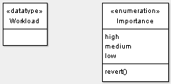
Figure 18.4, “ Possible model elements on a stereotype definition diagram. ” shows a stereotype definition diagram with all possible model elements displayed.
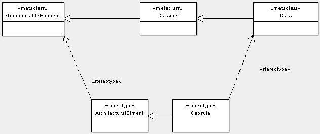
Various limitations exist in V0.26 of ArgoUML for stereotype definition diagrams. E.g. the implementation does not allow stereotype compartments to be shown on stereotype definition diagrams.
Another variant of the class diagram within the UML standard is the object diagram. There is currently no support for objects or links within ArgoUML class diagrams. Instead the ArgoUML deployment diagram does have both objects and links, and can be used to draw object diagrams.