Table of Contents
Blender provides several advanced Mesh Modeling features, mostly aimed at handling easily complex meshes or rather enabling economical, lov-vertex number modeling of complex smooth surfaces.
Relevant to Blender v2.36
With any regular Mesh as a starting point, Blender can calculate a smooth subdivision on the fly, while modelling or while rendering, using Catmull-Clark Subdivision Surfaces or, in short SubSurf. SubSurf is a mathematical algorithm to compute a "smooth" subdivision of a mesh. This allows high resolution Mesh modelling without the need to save and maintain huge amounts of data. This also allows for a smooth 'organic' look to the models.
Actually a SubSurfed Mesh and a NURBS surface have many points in common inasmuch as both rely on a "coarse" low-poly "mesh" to define a smooth "high definition" surface. But there are also notable differences:
NURBS allow for finer control on the surface, since you can set "weights" independently on each control point of the control mesh. On a SubSurfed mesh you cannot act on weights.
SubSurfs have a more flexible modelling approach. Since a SubSurf is a mathematical operation occurring on a mesh, you can use all the modelling techniques described in this chapter on the mesh. There are more techniques, which are far more flexible, than those available for NURBS control polygons.
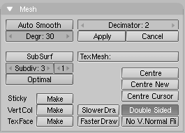
SubSurf is a Mesh option, activated in the
Editing Context Mesh Panel (F9 -
Figure 7.1, “SubSurf buttons ”).
The Num Buttons immediately below it define, on the left, the resolution
(or level)
of subdivision for 3D visualization purposes; the one on the right, the
resolution for rendering purposes. You can also use SHIFT-O if you are in
ObjectMode. This switches SubSurf On/Off. The SubSurf level can also be
controlled via CTRL-1 to CTRL-4,
but this only affects the visualization sub-division level.
Since SubSurf computations are performed both real-time, while you model, and at render time, and they are CPU intensive, it is usually good practice to keep the SubSurf level low (but non-zero) while modelling; higher while rendering.
From version 2.3 Blender has a new SubSurfed-related button:
Optimal. This changes the way SubSurf meshes are drawn and
can be of great help in modelling. Figure 7.2, “SubSurfed Suzanne.”
shows a series of pictures showing various different combinations on Suzanne's Mesh.
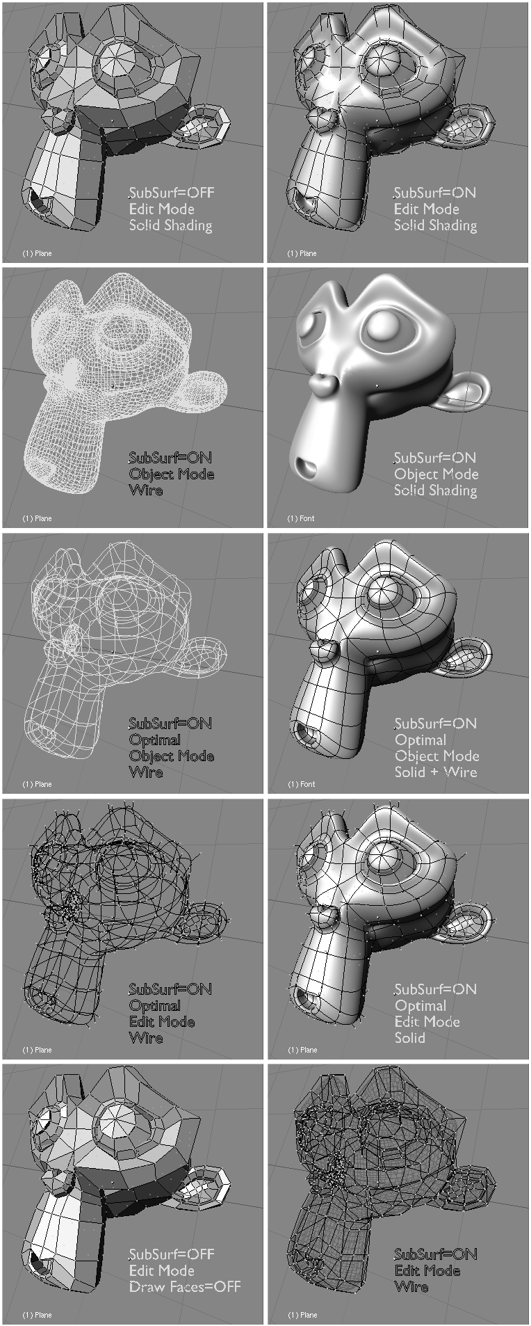
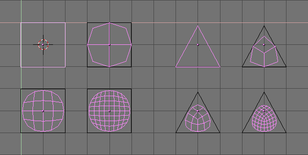
Figure 7.3, “SubSurf of simple square and triangular faces.” shows a 0,1,2,3 level of SubSurf on a single square face or on a single triangular face. Such a subdivision is performed, on a generic mesh, for each square or triangular face.
It is evident how each single quadrilateral face produces 4n faces in the SubSurfed mesh. n is the SubSurf level, or resolution, while each triangular face produces 3⋅4(n-1) new faces (Figure 7.3, “SubSurf of simple square and triangular faces.”). This dramatic increase of face (and vertex) number results in a slow-down of all editing, and rendering, actions and calls for lower SubSurf level in the editing process than in the rendering one.
Blender's subdivision system is based on the Catmull-Clarke algorithm. This produces nice smooth SubSurf meshes but any 'SubSurfed' face, that is, any small face created by the algorithm from a single face of the original mesh, shares the normal orientation of that original face.
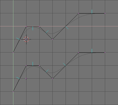
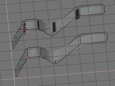
This is not an issue for the shape itself, as Figure 7.4, “Side view of subsurfed meshes. With random normals (top) and with coherent normals (bottom)” shows, but it is an issue in the rendering phase and in solid mode, where abrupt normal changes can produce ugly black lines (Figure 7.5, “Solid view of SubSurfed meshes with inconsistent normals (top) and consistent normals (bottom).”).
Use the CTRL-N command in EditMode, with all vertices selected, to make Blender recalculate the normals.
In these images the face normals are drawn cyan. You can enable drawing normals in the EditButtons (F9) menu.
Note that Blender cannot recalculate normals correcty if the mesh is not "Manifold". A "Non-Manifold" mesh is a mesh for which an 'out' cannot unequivocally be computed. Basically, from the Blender point of view, it is a mesh where there are edges belonging to more than two faces.
Figure 7.6, “A "Non-Manifold" mesh” shows a very simple example of a "Non-Manifold" mesh. In general a "Non-Manifold" mesh occurs when you have internal faces and the like.
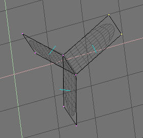
A "Non-Manifold" mesh is not a problem for conventional meshes, but can give rise to ugly artifacts in SubSurfed meshes. Also, it does not allow decimation, so it is better to avoid them as much as possible.
Use these two hints to tell whether a mesh is "Non Manifold":
The Recalculation of normals leaves black lines somewhere
The "Decimator" tool in the
MeshPanel refuses to work stating that the mesh is "No Manifold"
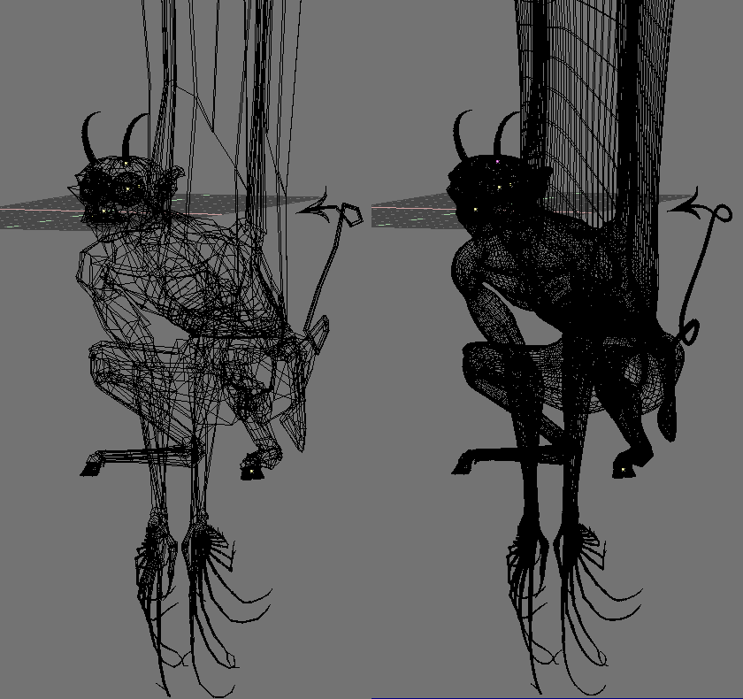
The SubSurf tool allows you to create very good "organic" models, but remember that a regular Mesh with square faces, rather than triangular ones, gives the best results.
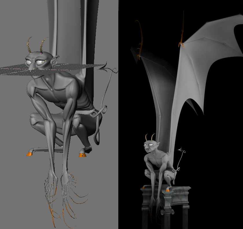
Figure 7.7, “A Gargoyle base mesh (left) and pertinent level 2 SubSurfed Mesh (right).” and Figure 7.8, “Solid view (left) and final rendering (right) of the Gargoyle. ” show an example of what can be done with Blender SubSurfs.