Relevant to Blender v2.33
In Blender 2.30 some brand new modelling tools were added. These focused on edges and faces, as opposed to vertices.
A key issue in modelling is often the necessity to add vertices in certain zones of the mesh, and this is often regarded as splitting, or adding, edges in a given region. Blender now offers two tools for this, a Knife Tool able to split edges in desired locations, and a Face Loop tool, able to select face paths and split them consistently.
Many Edge Tools are grouped in a menu which is linked to KKEY Hotkey, but each individual tool has its own hotkey as well.
In EditMode, by pressing ALT-B one activates the edge/face select tool. If ALT-B is pressed once, then Blender is in edge select mode. The edge under the cursor is highlighted cyan. For each end point in the edge the following operations are performed:
It checks to see if it connects to only 3 other edges.
If the edge in question has already been added to the list, the selection ends.
Of the 3 edges that connect to the current edge, the ones that share a face with the current edge are eliminated and the remaining edge is added to the list and is made the current edge.
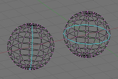
This way a loop of edges is highlighted (Figure 7.17, “One open (left) and one closed (right) Edgeloop.”). By pressing LMB such a highlighted loop is converted into a set of selected vertices. Any previously selected vertices become unselected. If you wish to add the highlighted loop to the current selection use SHIFT-LMB, while if you want to subtract the highlighted loop from the current selection use ALT-LMB.
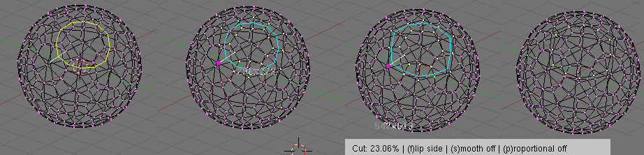
If ALT-B is pressed twice a Face Loop, rather than an Edge Loop, is highlighted. A face loop is made by two neighbouring edge loops and extends only to quadrilateral faces, ending when a triangular face is met (and the two bounding edgeloops merge into one). The same mouse actions apply as for the edge loops (Figure 7.18, “One open (left) and two closed (center and right) Faceloops.”).
Face loop selection is also invoked with SHIFT-R in EditMode.

The Loop tool allows you, eventually, to split, a loop of faces. This loop is defined as described in the previous section.
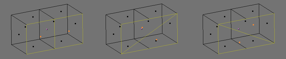
In EditMode press CTRL-R rather than SHIFT-R. The edge under the cursor is aquamarine, the median line of the corresponding face loop is highlighted yellow (Figure 7.19, “Splitting a Faceloop.”, left). Once the face loop selection is performed via LMB a cyan line is highlighted between the two edgeloops defining the faceloop.
One of the two vertices pertaining to the edge under the mouse pointer defining the edgeloop is highlighted via a big magenta dot (Figure 7.19, “Splitting a Faceloop.”, center left). Now by moving the mouse the cyan edge loop moves towards or away from the magenta dot. In the 3D Window header the distance of the edge loop from the reference magenta point is given as a percentage of the edge length.
You can force the edge to move in 10% steps by keeping CTRL pressed. You can flip the reference vertex of the reference edge (the magenta point) with FKEY (Figure 7.19, “Splitting a Faceloop.”, center right).
By clicking LMB the edge loop is created, all faces and internal edges of the face loop are split in half at the points highlighted by the cyan edge loop. (Figure 7.19, “Splitting a Faceloop.”, right).
This is a really useful way to refine a mesh in a SubSurface-friendly way.
By default the new, cyan, edge loop is created so that each edge is divided into two parts which are proportional one to the other and the proportionality ratio is the percentage given on the header (Figure 7.20, “Proportional and Smooth face cuts.”, left). You can force the new edge loop to stay at a given, fixed, distance from the edge loop to which the reference vertex belongs by switching proportional mode off with PKEY. This turns the highlighted edgeloop blue too (Figure 7.20, “Proportional and Smooth face cuts.”, center). PKEY acts as an on/off switch.
Furthermore, by default, new vertices for the new edge loop are placed exactly on the pre-existing edges. This keeps subdivided faces flat. If a smoother result is desired SKEY can be used, prior to finalazing the split, to set smooth mode on/off. If smooth mode is on then new vertices are not on the previous edge any more but displaced in the direction of the normal to the edge by a given percentage. A pop up asks for the percentage after LMB is pressed to finalize the split (Figure 7.20, “Proportional and Smooth face cuts.”, right).
Note
Both Face Loop tools are present in the KKEY menu too.
The Knife Tool works by subdividing edges if both their verts are selected and the edge is intersected by a user-drawn 'knife' line. For example, if you wish to cut a hole only in the front of a sphere, you can select only the front vertices, and then draw the line with the mouse.
To test the tool add a Grid Mesh. You will be in EditMode and all vertices are selected.
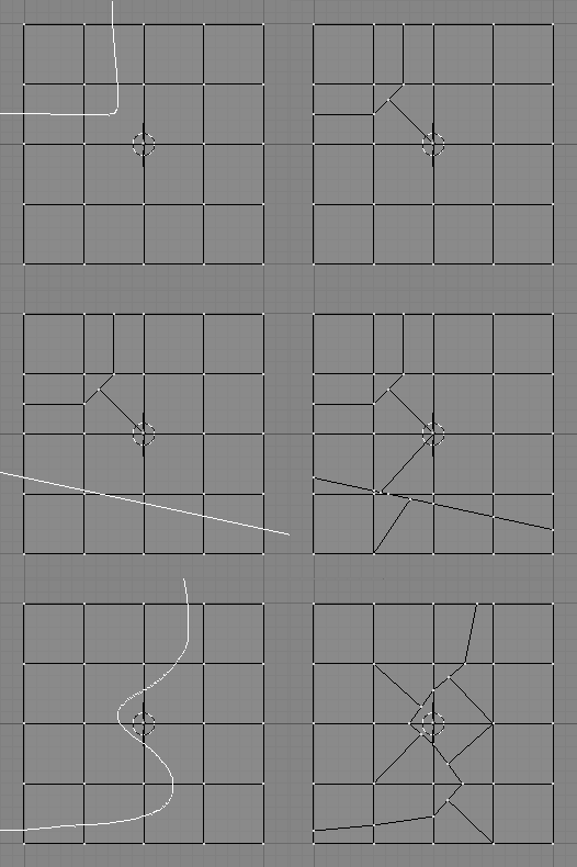
Press SHIFT-K to activate the Knife Tool. You are prompted to choose the type of cut:
Exact Line will divide the edges exactly where the knife line crosses them,
Midpoints divides an intersected edge at its midpoint.
For this cut, we chose Midpoints.
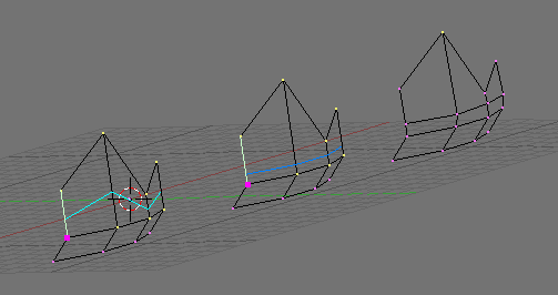
Now you can click LMB and start drawing. If you move and click LMB you draw straight segments from clicked point to clicked point; if you hold LMB pressed while dragging you draw freehand lines. The polylines can be drawn with an arbitrary number of segments, but the intersection routines only detect one crossing per edge. Crossing back over an edge multiple times does not perform additional cuts on it. MMB constrains drawing to an axis as expected. Snap to grid is not currently implemented, but is being looked at for future releases. When you have finished drawing your line, hit ENTER to confirm the cut. ESC at any time cancels the operation. Figure 7.21, “Midpoints knife with polyline (top); Exact Line knife with single segment (middle) and Exact Line freehand knife (bottom).” shows some examples.
Note
With a large mesh, it will be quicker to select a smaller number of vertices, those defining only the edges you plan to split since the Knife will save time in testing selected vertices for knife trail crossings.
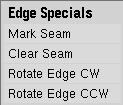
Edge editing includes some special tools. These are Edge Rotate
in both directions for editing meshes and Mark Seam and
Clear Seam that are used for UV mapping. For more on usage of
Seams see the section called “LSCM Unwrap”.
To access the Edge Rotate functions press CTRL-E
and choose Rotate Edge CW or Rotate Edge CCW
in the Edge Specials menu. See Figure 7.22, “Edge Specials menu.”.
To rotate an edge you need to select one edge or two adjacent faces.
This works in all three Edit Selection Modes.
See the section called “Vertex, Edge and Face Modes” for more on selection modes.
By selecting Rotate Edge CW or Rotate Edge CCW the selected edge or the common edge on the two faces is rotated clockwise or counter clockwise. See Figure 7.23, “Selected Edge Rotated CW and CCW.” and Figure 7.24, “Common Edge rotated CW and CCW.”.