The aim of this section is to get you started with ArgoUML. It takes you through obtaining the code and getting it running.
Since ArgoUML is written in 100% pure Java, it should run on any machine with Java installed. Java version 5 or later is needed. You may have this in place, but if not the latest version can be downloaded free from www.java.com. Note that you only need the Java Runtime Environment (JRE), there is no need to download the whole Java Development Kit (JDK).
ArgoUML needs a reasonable amount of computing resource. Any PC which is able to run an operating system with a graphical user interface will suffice. Download the code from Download section of the project website argouml.tigris.org. Choose the version that suits your needs as described in the section below.
You have three options for obtaining ArgoUML.
Run ArgoUML directly from the Web Site using Java Web Start. This is the easiest option.
Download the Windows installer program. This is the right option if you are on Windows and intend using ArgoUML regularly.
Download the binary executable code. Unless you are on Windows, this is the right option if you intend using ArgoUML regularly and is not that difficult.
Download the source code using Subversion and build your own version. Choose this option if you want to look at the internal workings of ArgoUML, or want to join in as a developer. This option does require the whole JDK (see Section 3.4.1.1, “ System Requirements ”).
All four options are freely available through the project web site, argouml.tigris.org.
There are two steps to this.
Install Java Web Start on your machine. This is available from java.sun.com/products/javawebstart, or via the
Java Web Startlink on the ArgoUML home page.Click on the
Launch latest stable
	                release
link on the ArgoUML home page.
Java Web Start will download ArgoUML, cache it and start it the first time, then on subsequent starts, check if ArgoUML is updated and only download any updated parts and then start it. The ArgoUML home page also provides details on starting ArgoUML from the Java Web Start console.
If you choose to download and install using the Windows installer, you will have a choice of downloading the latest stable version of the code (which will be more reliable, but not have all the latest features), or the current version (which will be less reliable, but have more features). Choose according to your own situation.
The install wizard gives you the opportunity to install the latest "JRE" (Java Runtime Environment). There is no need to select this if you already have a Sun Java installed, version 5 or better.
If you choose to download the binary executable, you will have a choice of downloading the latest stable version of the code (which will be more reliable, but not have all the latest features), or the current version (which will be less reliable, but have more features). Choose according to your own situation.
ArgoUML comes in .zip or
tar.gz flavors. Choose the former if you are a
Microsoft Windows user, and the latter if you are running
some flavor of Unix.
There is also a Mac OS X version with .app.tgz
extension.
Unpacking is as follows.
On Windows. Unzip the
.zipfile with WinZip, or if your version of Windows supports it, copy the files out of the compressed folder and put them into a directory of your choosing.On Unix. Use GNU tar to unzip and break out the files to a directory of your choice
tar zxvf <file>.tar.gz. If you have an older version of tar, thezoption may not be available, so usegunzip < file.tar.gz | tar xvf -.
You should have a directory containing
a number of .jar files and a
README.txt.
If you get completely stuck and you have no local assistance, try the web site, particularly the FAQ. If this still doesn't solve the problem, try the ArgoUML users' mailing list.
You can subscribe through the mailing lists section
of the project web site
argouml.tigris.org, or send an empty message to
[email protected] with the subject line
subscribe.
You can then send your problem to [email protected] and see how other users are able to help.
The users' mailing list is an excellent introduction to the live activity of the project. If you want to get further involved there are additional mailing lists that cover the development of the product and issues in the current and future releases.
To run ArgoUML depends on whether you use Microsoft Windows or some flavor of Unix.
On Windows. If you used the installer, starting ArgoUML is a matter of clicking on its icon. In case you installed the binairy executable, read on: Start an MSDOS shell window by e.g. using Start/Run with “command” in the text window. In the window change to the directory holding your ArgoUML files and type
java -jar argouml.jar. This method has the advantage that progress and debugging information is visible in the DOS window. Alternatively use the supplied batch file (.bat), or create one containing the above command, with a shortcut to it on the desktop. The batch file should end with a "pause" statement in case any debugging information is created during a run. On some systems, simply (double) clicking on theargouml.jarfile works. On others doing so initiates a zip utility. Refer to your operating system instructions or help facility to determine how to configure this.On Unix. Start a shell window and type
java -jar argouml.jar
It's unusual to encounter problems if you have made a successful download. If you can't solve the problem. Try the users' mailing list (see Section 3.4.1.6, “ Problems Downloading and Installing ”).
Wrong JRE. The most common issue is not having a new enough Java Runtime Environment (it must be version 5 or later).
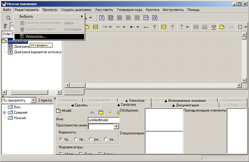
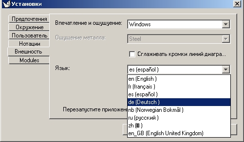
Wrong language. If the product came up in a language you can't read or just don't want, go to the second leftmost menu item in the menu bar at the top of the screen. Select the bottom most menu entry in the drop down. Figure 3.5, “ Setting Language in the Appearance Pane ” shows this in Russian. Then click on the second tab from the bottom in the column of tabs on the left. Drop down the list as shown in Figure 3.5, “ Setting Language in the Appearance Pane ” and select a language. Note that the languages are listed in themselves. The language shown as being selected is German in which the word for “German” is “Deutsch”. You will have to exit ArgoUML and restart it for the change to take effect. Use the X button at the upper right.
Before beginning the Case Study, you need to become familiar with the user interface. Start by reading the introduction to the User Interface Reference. See Chapter 8, Introduction . You should also read the Section 8.2, “ General Mouse Behavior in ArgoUML ”
As you go through this tutorial you will be told what to do, and when to do it but how to do it will often be left to the User Interface Reference. It is not necessary at this point to read all of the Reference, but you should leaf through enough of it to become familiar with how to find things in it. Every attempt will be made to direct you to the appropriate part of the Reference at those points in the tutorial where they apply.
Figure 3.6, “ Initial ArgoUML window ”, shows the main ArgoUML window as it appears when ArgoUML is first entered.
Grab the vertical divider bars and move them back and forth. Grab the horizontal divider bar and move it up and down. Play around a little with the little arrows at the left or top of the divider bars. See Section 8.3, “ General Information About Panes ”.
The menu bar and toolbars give access to all the main features of ArgoUML. As is conventional, menu options and toolbar options that are not available (disabled) are grayed out and menu items that invoke a dialog box are followed by an ellipsis (...). At this time you should read Chapter 9, The Toolbar and Chapter 10, The Menu bar .
File menu. The standard file menu entries present no surprises and we will just use them when needed without first showing how they work. A number of other actions are available that are peculiar to ArgoUML and we will go over them here.
File=>Revert to Saved. This has the same effect as File=>Open Project selecting the current project.
Export/Import. Select the project line at the top of the Explorer. It should say "untitledModel" unless you have changed it. Perform a File=>Export XMI action using "DeleteThis" for an output name in the file chooser dialog. Select the "Properties" tab in the "Details Pane" and change the name to something else, anything will do. Perform a File=>Import XMI action. It will ask you whether you want to save the changes you have just made. Click on "No" and then in the file choosed that comes up select the "DeleteThis.xmi" file that you just wrote out. Observe that the name of the model has reverted back to what you had saved.
File=>Import Sources. We will cover this later. You can't test it now unless you have some Java source code of your own handy.
File=>Export (All) Graphics. In the Explorer Pane select one of the diagrams. Either "Class Diagram 1" or "Use Case Diagram 1" (assuming you haven't renamed or deleted them). Perform a File=>Export Graphics action. When the file chooser opens it defaults to the last name you saved something to (even from a project no longer open). The file chooser allows you to select from a number of formats. Drop down the "Files of type" combobox and observe the choices. Cancel out as there is nothing useful to save. Perform a File=>Export All Graphics action. Notice that this time you can't specify a file name and you can't select a file format. ArgoUML will allow you only to select an output directory. It will then create a file for each of your diagrams using the diagram name for the file name and an extension determined by the default graphics format. Actually, although you can't select file names in the browser panel, you can type one into the edit box. But, if you do that, nothing at all will happen. You will learn more about the default graphics format when we get to the Edit menu.
File=>Notation. We are going to get a little ahead of ourselves here and do a little class diagram work so you can see what notation is all about. In the Explorer Pane select or create a class diagram. See Section 10.6, “ The Create Menu ” and Section 12.4.3, “ Drawing Tools ”. Create a class in the diagram. Go to the Detail Pane and create an attribute in the class. See Section 18.6.2, “ Class Property Toolbar ”. In the Properties tab of the Detail Pane change the multiplicity to "1..*". Now go the the File Menu and select Notation. Go back and forth between UML and Java observing the changes in the display in the Edit Pane.
File=>Project Properties. In the Project Properties dialog it is possible to configure the project specific settings. It contains the tabs for User, Profiles, Notations and Diagram Appearance. For instance, to change the Notation language in the Project Properties dialog, click on File=>Project Properties and select the Notations tab. Set the Notation Language to UML1.4. Turn on all of the options and click Apply. Then turn off all of the options and click Apply observing the changes in the diagram. Set the Default Shadow Width to 8 and click Apply. Notice that nothing happens. This is because you are not setting the Shadow Width, but its default. The next time you create a class in a diagram, this new shadow value will apply.
Edit menu. The edit menu does not look like what you are used to in other products. There are no "Cut", "Copy", or "Paste" actions. All of the choices are peculiar to ArgoUML so we are going to cover all of them in detail.
Edit=>Select.
Select a class diagram in the Explorer Pane. If there is none there create one using Create=>New Class Diagram. Create three classes using the class tool described in the User Interface Reference section on Class Diagram Specific Tools. Double click on it and then click in the Edit Pane for the class diagram in three different locations.
Undo the current mode by clicking on the "Select" tool. See Section 12.4.1, “ Layout Tools ”. This allows you to do things in the Edit Pane other than creating classes.
Open everything in the Explorer Pane tree, so that all elements are visible. Now activate the first menu item: Edit=>Select=>All. Obviously, this selects all elements, but only those on the current diagram - elements only present on another diagram are not selected this way. This function is e.g. usefull if you have a big diagram, and need to shift everything to add some more elements at the left or top of the diagram.
Each of the classes in the diagram has three vertically spaced sections. Double click in the top section of each class and enter a name for the class then hit the enter key. Just name the classes "A", "B", and "C". Select class A, then class B, and then class C either in the Edit Pane or in the Explorer Pane.
Now do an Edit=>Select=>Navigate Back. Class B should now be selected. Do another Edit=>Select=>Navigate Back. Class A should now be selected. Finally, do an Edit=>Select=>Navigate Forward. Class B should be selected again.
Do an Edit=>Select=>Invert Selection. Classes A and C should now be selected. Do another Edit=>Select=>Invert Selection. Class B should be selected again.
Do an Edit=>Remove From Diagram. Notice that class B is gone from the diagram but still exists in the Explorer Pane.
Select class B in the Explorer Pane, right click on it and choose "Add to Diagram". Move the cursor back onto the Edit Pane and left click on some part of the diagram where you think it will fit. You should be pretty much right back where you were before you removed it from the diagram. Do an Edit=>Delete From Model. Now class B should be gone both from the diagram and from the Explorer Pane.
Edit=>Configure Perspectives. Read Section 11.5, “ Configuring Perspectives ”. We aren't going to go into this at this point as it needs much larger projects to be displayed than we have available at this point.
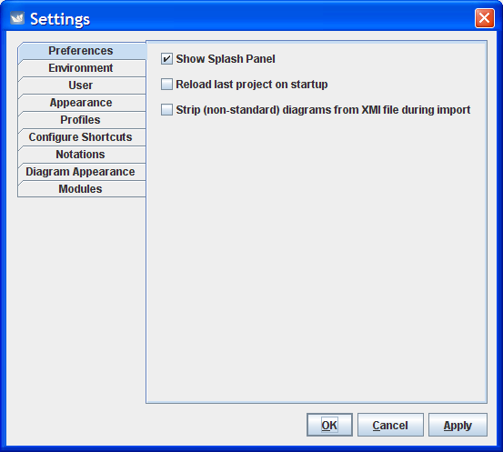
Edit=>Settings=>Preferences. Enter Help=>About ArgoUML. Look at the panel in the "splash" tab. This is known as the Splash Panel. Go to Edit=>Settings=>Preferences. Turn off the "Show Splash Panel" check button. Exit from ArgoUML and restart it. Note that the splash panel does not show during the load.
Edit=>Settings=>Environment. Do File=>Export Graphics and observe the file extension that shows at the bottom of the file chooser dialog in the "Files of type" combobox. Go to the Edit=>Settings=>Environment editor and pick some other value for Default graphics format. Click "Apply" and then "OK". Go back to the File=>Export Graphics dialog and notice that the new format is now the default.
Edit=>Settings=>User. Enter your name and email address.
Edit=>Settings=>Appearance. Change the "Look and Feel:" to Metal." Note that the "Metal Theme:" editor becomes anabled. Change the theme to "Very Large Fonts." Click on "Apply" and then "OK." Notice that nothing has happened. Exit from ArgoUML and reopen it. The display should be markedly different. You can change it back or leave it that way as you prefer.
Edit=>Settings=>Profiles. Look in the Explorer Pane under "Profile Configuration". The only folder by default is the UML 1.4 profile. Now go to Edit=>Settings=>Profiles and look at the field "Default Profiles". It only contains the same UML 1.4 profile. Add the Java profile to it, and press OK.
If you now look at the Explorer Pane, nothing has changed, since you adapted the default setting, not the project setting. Press File=>New and check out the profiles in the Explorer Pane: it now shows both the UML 1.4 profile and the Java profile.
Many examples in this manual presume that the Java profile is available,so you may best leave it enabled.
Edit=>Settings=>Configure Shortcuts. (To be written).
Edit=>Settings=>Notations. We played around with this earlier with the File=>Notation and File=>Project Properties menu items. Start another copy of ArgoUML resize each copy so they can be seen at the same time next to each other. On one of them set the Notation Language to UML (the actual choice will have a version number with it). On the other set the Notation Language to Java.
On both of them do the following. Turn all of the check boxes on. Do a File=>New, create a class in a class diagram. Double click in the attributes section to create an attribute. Double click in the operation section to create a method. Observe the difference in the displays.
Edit=>Settings=>Diagram Appearance. This settings makes it possible to change the font and font-size used in the diagrams. Hence this setting does not influence the font used in the UI of ArgoUML itself. The default font for ArgoUML is Dialog.
Edit=>Settings=>Modules. This shows the currently loaded modules. We are not going to mess with it in this version of the tutorial.
View menu. This allows you to switch between diagrams, find model elements in the model, zoom in a diagram, adjust the grid, toggle page break display, and show an XML representation of the project. Do a File=>New to get back to a known point. Create an example of each diagram type not already in the Explorer Pane. Click on the (+) sign widgets in the Explorer Pane to expand the tree nodes. Select the class diagram and give it a name.
View=>Goto Diagram brings up a Go To Diagram panel. Select the class diagram entry in this panel and click on the "Go to Selection" button. There should be 0 nodes and 0 edges in the description column. Click on the "Close" button. In the Details Pane (Properties tab) enter the name as "Blort". Create two classes in the class diagram and go back to View=>Goto Diagram. You should now see 2 nodes and 0 edges shown. Click on the "Close" button again and link the classes with one of the "line" items like association or generalization. Go back to View=>Goto Diagram and you should see 2 nodes and 1 edge(s). Click on the "Close" button again and create a third class. Run the mouse over the icons in the toolbar until you find the one with the tooltip "New Association Class." Click on this tool and then connect the new class to one of the others. Having clicked on the "New Association Class" tool move the mouse over the new class. Press and hold down button 1. Move the mouse over one of the other classes and release button 1. Go back to View=>Goto Diagram and you should see 3 nodes and 2 edge(s). Even though it is a class and has a two dimensional representation, it counts as an edge not a node. Select other entries in this panel and click on the "Go to Selection" button in the Go To Diagram panel. Observe the changes in the Explorer Panel.
View=>Find. At this point you should have three normal classes and an association class in the Explorer Pane. Name them "AA", "AB", "B", and "C". Perform a View=>Find operation. Click on the "Find" button. Notice that an "* in *" tab is created below. This tab should show pretty much everything. In the "In Diagram" editor change the "*" to "B*" and click on the "Find Button" observing the contents of the new tab with "* in B*" as a tab label. You should see the three classes, the link (such as an association), and the association class. In the Element Type drop down box select "Interface" and click on the Find button. The new tab "* in B* Inte..." should have no entries in it as we have defined no interfaces. In the Element Type drop down box select "Class" and click on the Find button. The new tab "* in B* Class" should have one fewer entries in it than the "* in B*" tab. Switch back and forth between these two observing the difference. In various of these tabs select an item and click on the "Go To Selection" button observing the change in the selection shown in the diagram and in the Explorer Pane.
View=>Zoom. As an exeption to a general rule the toolbar equivalent of View=>Zoom does not operate in the same way as the corresponding menu item. Highlight View=>Zoom. and a submenu will appear that contains "Zoom Out", "Zoom Reset" and "Zoom In". Click on these a few times observing the effect on the diagram then click on the Zoom tool bar icon. This is a magnifying glass next to a down arrow head. You should see a graduated slider bar tool. Grab the pointer in this tool and move it up and down observing the effect on the diagram.
View=>Adjust Grid.
View=>Adjust Snap.
View=>Page Breaks.
View=>XML Dump.
Create Diagram menu. This allows you to create any one of the seven UML diagram types (class, use case, state, activity, collaboration, deployment and sequence) supported by ArgoUML.
State and activity diagrams can only be created when a class or actor is selected, even though the relevant menu entries are not grayed out if this has not been done (nothing will happen under this circumstance).
Arrange menu. This allows you to align, distribute and reorder model elements on a diagram and set the layout strategy for the diagram.
Generation menu. This allows you to generate Java code for selected classes or all classes.
Critique menu. This allows you to toggle the auto-critique on and off, set the level of importance of design issues and design goals and browse the critics available.
Tools menu. This menu is permanently grayed out unless there is some tool available in your version of ArgoUML.
Help menu. This menu gives access to details of those who authored the system, and where additional help may be found.
File Toolbar. This toolbar contains some of the tools from the File menu.
Edit Toolbar. This toolbar contains some of the tools from the Edit menu.
View Toolbar. This toolbar contains some of the tools from the View menu.
Create Diagram Toolbar. This toolbar contains some of the tools from the Create Diagram menu.
At this time you should take the time to read Chapter 11, The Explorer . The Explorer Pane is fundamental to almost everything that you do and we will be coming back to it again and again in what follows. In fact you will recall we have had to use it already.
There is an expand or contract control in front of the package symbol for “untitledModel” in the Explorer Pane and the package symbol for “Medium” in the To-Do Pane. Click on these controls and observe that these panes are tree widgets that behave pretty much as you would expect them to. The expand or contract control is either plus (+)/minus (-) sign or knob with a right or bottom pointer depending upon the look and feel that you have chosen for an appearance.
Select alternately Class Diagram 1 and Use Case Diagram 1 observing that the detail pane changes to track to the selected item in the Explorer. The detail pane is described in Chapter 12. It is not necessary to read Chapter 12 at this point, but it couldn't hurt.
At this point take some time to read Chapter 12, The Editing Pane .
As we go through the Editing pane changes will sometimes occur in the Details and the To-Do panes. Pay no attention to them for now. We will attend to them when we cover those panes.
Select "Class Diagram 1" in the Explorers Pane. The name is unimportant, if you have changed it, just select the new name. If you have deleted it, first perform a Create=>New Class Diagram action. Click on the "New Package" button in the Edit Pane tool bar. Click somewhere in the edit pane. In the Explorer notice that a package appears named (unnamed Package).
Double click on the "New Class" button in Edit Pane the tool bar. Click first within the package and once outside of it. Notice that within the Explorer, two classes appear in the tree both named (unnamed Class) one of them attached to the model node and the other attached to the (unnamed Package) node.
Click the Select button in the Edit Pane tool bar so you can do things in the Edit Pane without adding new Classes. In the Explorer select the class that is not subordinate to the package. This selects the corresponding class in the diagram. Grab this class and move it into the package. Notice that in the Explorer this class is now also subordinate to the package node.
In the diagram select the other class. Notice that in the Explorer, the selected node changes correspondingly. Grab this class and move it outside of the package and watch what happens in the Explorer.
At this point take some time to read Chapter 13, The Details Pane .
![[Note]](images/note.png) | Note |
|---|---|
|
At this point take some time to read Chapter 14, The To-Do Pane .
| Note |
|---|---|
|
In general diagrams are drawn by using the edit pane toolbar to select the model element desired and clicking in the diagram at the position required.
Model elements that are already in the model, but not on a
diagram, may be added to a diagram by selecting the
model element in the explorer, using
Add to Diagram from the drop down menu (button 2)
over that model element, and then clicking button 1 at the
desired location on the diagram.
As well as UML model elements, the Edit pane toolbar provides for general drawing objects (rectangles, circles, lines, polygons, curves, text) to provide supplementary information on diagrams.
There are several ways to move diagram elements.
Select the elements you want to move. By holding down the Ctrl key while selecting you can select several elements to move at the same time.
Now hit your arrow keys. Your elements move a little with every key stroke.
If you also hold down the Shift key, they move a bit faster.
Figure 3.6, “ Initial ArgoUML window ” shows the ArgoUML main window as it appears as right after start-up
The main window's client area, below the menu and toolbar, is subdivided into four panes. Starting at the leftmost top pane, and working around the clock, you can see the Explorer, showing a tree view of your UML model, the Editing Pane with its toolbar, two scroll bars and gray drawing area, the Details Pane with the ToDoItem tab selected, and the To-Do Pane with a tree view of the to do items, ranked in various ways selected via the drop down list at the top of the pane.
Each time ArgoUML is started up without a project
file as an argument, a new blank project is created. This
project contains a model called
untitledModel. This model contains a blank
Class Diagram, called class diagram 1,
and a blank Use Case Diagram called
use case diagram 1.
The model and both empty diagrams can be seen in the explorer, which is the main tool for you to navigate through your model.
Let's assume for a moment that this is the
point where you want to start modeling a new purchasing
system. You want to give the name
“purchasingmodel” to your model, and you
want to store it in a file called
FirstProject.
For now ArgoUML; saves diagrams using an earlier proposed standard, Precision Graphics Markup Language (PGML). However it has the option to export graphical data as SVG for those who can make use of it. When ArgoUML; supports UML 2.0, it will store diagrams using the UML 2.0 Diagram Interchange format.
First, let's save the model in it's
current (empty and unnamed) state. On the menu bar, click
on File, then on
Save Project As... as shown in
Figure 3.8, “
Invoking Save Project As...
”.
Please notice that the File menu contains the usual options for creating a new project, for opening an existing project, for saving a project under a new name, for printing the currently displayed diagram, for saving the currently displayed diagram as a file, and for program Exit.
Some of these menu commands can be invoked by pressing key combinations, as indicated on the drop-down menu. For instance, holding down the “Ctrl” key, and pressing “N”, will create a new project.
In the current version, ArgoUML can only contain one active project at a time. In addition, a project can only contain one UML model. Since an UML model can contain an unlimited number of elements and diagrams, this should not present any serious limitations, even for modeling quite large and complex systems.
But let's go back to saving our project. After
clicking on the Save Project As... menu
command, we get the file chooser dialog to enter the file
name we wish to use as shown in
Figure 3.9, “
File Chooser Dialog
”.
This is a standard Java FileChooser. Let's go over it in some detail.
The main, outstanding feature, is the scrollable folders list in the center of the dialog. By using the scroll bar on the right, you can move up and down in the list of folders contained inside the currently selected folder. If it is scrollable or not depends on the amount of files and folders shown and also how they are shown. If everything fits the window is not scrollable as seen in the picture.
Double-clicking on one of the displayed folders navigates you into that folder, allowing you to quickly navigate down into the folders hierarchy on your hard disk.
Notice that only folder names, and no file names
are displayed in the scrollable area. Indeed, the dialog
is currently set up in order to show only ArgoUML project
files with an extension of .zargo, as
can be seen on the lower drop-down control labeled
Files of Type:.
Also notice that the currently selected
folder's name is displayed in the upper drop-down
control labeled Look in:. A single
click on a folder inside the scrollable area does select
that folder on screen but does not select the folder for
saving.
At the top of the dialog, above the scrollable folder chooser area, there are a few more folder navigation tools.
 The Folder drop-down
control. Clicking on the down-arrow displays a tree
view of the folder hierarchy, allowing you to
navigate quickly up the hierarchy, and at the same
time to quickly determine where in the hierarchy we
are currently positioned.
The Folder drop-down
control. Clicking on the down-arrow displays a tree
view of the folder hierarchy, allowing you to
navigate quickly up the hierarchy, and at the same
time to quickly determine where in the hierarchy we
are currently positioned.
 The Folder-Up icon.
Clicking on this icon will bring us to the parent
folder of the current folder.
The Folder-Up icon.
Clicking on this icon will bring us to the parent
folder of the current folder.
 The Home Folder icon.
Clicking on this icon will bring us to our home
directory.
The Home Folder icon.
Clicking on this icon will bring us to our home
directory.
 The New Folder icon.
Clicking on this icon will create a new folder called
"New Folder" under the current folder.
After the folder is created selecting it an clicking
in the name allows us to select the name of our
choice.
The New Folder icon.
Clicking on this icon will create a new folder called
"New Folder" under the current folder.
After the folder is created selecting it an clicking
in the name allows us to select the name of our
choice.
 The Folders Presentation
Icon.
The Folders Presentation
Icon.
OK, now we navigate to the directory where we want
to save our ArgoUML project, fill in the
File name: with an appropriate name, such as
“FirstProject” and click on the
Save button.
You have now an active project called
FirstProject, connected to the file
FirstProject.zargo.
ArgoUML saves the diagram information in a PGML
file (with extension .pgml, the model
information in an XMI file (with extension
.xmi and information about the project in a
file with extension .argo. See
Section 3.4.3.2.2, “
Precision Graphics Markup Language (PGML)
” and
Section 3.4.3.3, “XMI” for more about PGML and XMI
respectively.
All of these are then zipped to a file with
extension .zargo. You can easily
extract the .xmi file from the
.zargo file using any old generic
ZIP application. Give it a try
and look into the magic of Argo.
![[Warning]](images/warning.png) | Warning |
|---|---|
Be aware that double clicking will launch a
|
GEF is the software package that is the foundation of the diagrams that appear in the Editing Pane. GEF was an integral part of ArgoUML but has been separated. Like ArgoUML it is an open source project available via Tigris.
PGML is the current storage format for diagram information used in ArgoUML. In the future, PGML will be replaced by the UML 2.0 Diagram Interchange format.
PGML is a predecessor of SVG (see Section 3.4.3.2.5, “ Scalable Vector Graphics (SVG) ”. It was dropped by the W3C Consortium.
Currently there are no other tools that we know of working on PGML.
Select a diagram, then go to
File=>Export Diagrams.
You
can generate GIF, PostScript, Encapsulated PostScript or
SVG format.
A World Wide Web Consortium (W3C) standard vector graphics format ( http://www.w3.org/TR/SVG/).
Support is built in to modern browsers, but you can also get a plugin for older browsers from adobe.com.
Select
.svgas the file type.Type the name of the file as you like with the
.svgtag at the end. Examplemyumldiagram.svg
Et viola! SVG! Give it a try and zoom around a little... They are not pretty though, so if you know anything about rendering beautiful SVG let us know.
Most modern browsers support SVG. If yours doesn't try Firefox or get a plugin for your current browser from adobe.com
| Note |
|---|---|
You will not have scroll bars for your SVG unless it is embedded in HTML. Good luck and let us know what you find! |
ArgoUML supports XMI 1.0, 1.1, and 1.2 files which contain UML 1.3 and UML 1.4 models. For best compatibility with ArgoUML, export your models using UML 1.4 and XMI 1.1 or 1.2. Be sure to turn off any proprietary extensions (such as Poseidon's diagram data).
With UML versions earlier than UML 2.0, it isn't possible to save diagram information, so no diagrams will be transferred.
There is also a tool that converts XMI to HTML. For more information, see http://www.objectsbydesign.com/projects/xmi_to_html_2.html.
In the Export project to XMI dialog, but
sure to clear the selection of Save with diagram
dataliteral>.
Versions of ArgoUML prior to 0.19.7 supported UML 1.3/XMI 1.0. After this time, the save format is UML 1.4/XMI 1.2 which is not backward compatible. Newer versions of ArgoUML will read projects written by older versions, but not vice versa. If you might need to return to an older version of ArgoUML you should be careful to save a backup of your old projects.
Additionally, if you write XMI files which need to be read by other tools, you should take into account the different versions. Most modern UML modelling tools should read UML 1.4, but you may have in-house code generators or other tools which are tied to UML 1.3.
XMI compatibility between UML modeling tools has improved over the years, but you may still occasionally run into problems.
ArgoUML will not read XMI files which contain UML 1.5 or UML 2.0 models, but it should be able to open most UML 1.4 and UML 1.3 files. If you find one that it can't open, please file a bug report so that a developer can investigate.
It is possible to compile your generated code with ArgoUML, you still need to implement method bodies, though, to get usable results.
At the moment you cannot write code for methods (operations) within ArgoUML. The source pane is editable, but the changes are ignored. ArgoUML is a pure design tool for now, no IDE functionality but the desire is there. You might consider using Forte and ArgoUML together -it's a good work around!
You can help us out there if you'd like!
Design critics are part of the practical application of the theories of Cognitive Psychology that are implemented in ArgoUML. See Section 3.3.1, “ Cognitive Psychology ”
Where do we stand now? A new project has been
created, and is stored in the file
FirstProject.zargo.
Figure 3.10, “
ArgoUML Window Having Saved FirstProject.zargo
” shows how your ArgoUML
window should look at this stage.
The project contains a top-level package, called
untitledModel, which contains a class
diagram and a use case diagram.
If we look carefully at the screen, we can see that
the "Medium" folder in the To-Do Pane (the lower
left pane) must contain some items, since its activation
icon
 is displayed.
Clicking on this icon will open the
"Medium" folder. An open folder is indicated by
the
 icon.
icon.
But what is this “To-Do” Pane anyway. You haven't recorded anything yet that has to be done, so where do these to do items originate.
The answer is simple, and is at the same time one of the strong points of ArgoUML. While you are working on your UML model, your work is monitored continuously and invisibly by a piece of code called a design critic. This is like a personal mentor that watches over your shoulder and notifies you each time he sees something questionable in your design.
Critics are quite unobtrusive. They give you a
friendly warning, but they do not force you into design
principles that you don't want or like to follow. Let
us take a look at what the critics are telling us. Click on
the
icon next to the
Medium folder, and click on the
Revise Package Name UntitledModel item.
Figure 3.11, “
ArgoUML Window Showing the Critic Item
Revise Package Name UntitledModel
” shows how your
screen should now look.
Notice that your selection is highlighted in red in the To-Do Pane, and that a full explanation appears now in the Details Pane (the lower right pane). You may have to re-size your Details Pane or to scroll down in order to see the full message as displayed in our example.
What ArgoUML is trying to tell you is that usually,
package names are written in lower cases. The default top
level package created by ArgoUML is called
untitledModel and therefore violates a sound
design principle. (Actually, this could be considered as a
bug within ArgoUML, but it comes in handy to demonstrate
the working of critics).
At this point, you can choose to change the package name manually or to impose silence on the design critic for some time or permanently
We will do nothing of this (we'll come back to it when we talk about the design critics in more detail) but we'll use another handy feature of ArgoUML -an auto-correct feature.
In order to do that, just click on the
Next button on the Details Pane. This will cause
a renaming wizard to be displayed inside the properties
panel, proposing to use the name
untitledmodel (all in lower case).
Replace the name untitledmodel
with purchasingmodel, and click on the
Finish button.
Figure 3.12, “
ArgoUML Window Showing the Critic Wizard to Rename
the Package
” shows how the ArgoUML
window will now look.
Watch now how the design critic note in the To Do
panel disappears, leaving only the
Add Elements to Package purchasingmodel note in
the To-Do list.
If this doesn't happen at once, wait for a few seconds. ArgoUML makes heavy use of several threads of execution that execute in parallel. This can cause delays of a few seconds before the information gets updated on the screen.
The package name change should also be reflected in the explorer, in the top left corner of your ArgoUML window.
We are now ready to create our first UML diagram, a Use Case diagram, but first let's save what we've done so far.
Click on the File menu item, and
select Save Project. You can now safely
exit ArgoUML without losing your work so far, or go on
creating your first diagram.