Table of Contents
Before you can understand how to design effectively with materials, you must understand how simulated light and surfaces interact in Blender's rendering engine and how material settings control those interactions. A deep understanding of the engine will help you to get the most from it.
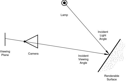
The rendered image you create with Blender is a projection of the scene onto an imaginary surface called the viewing plane. The viewing plane is analogous to the film in a traditional camera, or the rods and cones in the human eye, except that it receives simulated light, not real light.
To render an image of a scene we must first determine what light from the scene is arriving at each point on the viewing plane. The best way to answer this question is to follow a straight line (the simulated light ray) backwards through that point on the viewing plane and the focal point (the location of the camera) until it hits a renderable surface in the scene, at which point we can determine what light would strike that point. The surface properties and incident light angle tell us how much of that light would be reflected back along the incident viewing angle (Figure 10.1, “Rendering engine basic principle.”).
Two basic types of phenomena take place at any point on a surface when a light ray strikes it: diffusion and specular reflection. Diffusion and specular reflection are distinguished from each other mainly by the relationship between the incident light angle and the reflected light angle.
Relevant to Blender v2.31
Light striking a surface and then re-irradiated via a Diffusion phenomenon will be scattered, i.e., re-irradiated in all directions isotropically. This means that the camera will see the same amount of light from that surface point no matter what the incident viewing angle is.
It is this quality that makes diffuse light viewpoint independent. Of course the amount of light that strikes the surface depends on the incident light angle. If most of the light striking a surface is reflected diffusely, the surface will have a matte appearance (Figure 10.2, “Light re-irradiated in the diffusion phenomenon.”).

Since version 2.28, Blender has implemented three different mathematical formulae to compute diffusion. And, even more notably, the diffusion and specular phenomena, which are usually bound in a single type of material, have been separated so that it is possible to select diffusion and specular reflection implementation separately.
The three Diffusion implementations, or shaders, use two or
more
parameters each. The first two parameters are shared by all Diffuse Shaders
and are the Diffuse color,
or simply color, of the material, and the amount
of incident light energy that is actually diffused. This latter quantity, given
in a [0,1] range, is actually called Refl in the interface.
The implemented shaders are:
Lambert - This was Blender's default diffuse shader up to version 2.27. As such, all old tutorials refer to this, and all pre-2.28 images were created with this. This shader has only the default parameters.
Oren-Nayar - This shader was first introduced in Blender 2.28. It takes a somewhat more 'physical' approach to the diffusion phenomena because, besides the two default parameters, it has a third one which is used to determine the amount of microscopical roughness of the surface.
Toon - This shader was first introduced in Blender 2.28. It is a very 'un-physical' shader in that it is not meant to fake reality but to produce 'toonish' rendering, with clear light-shadow boundaries and uniformly lit/shadowed regions. Even though it is relatively simple, it still requires two more parameters which define the size of the lit area and the sharpness of the shadow boundaries.
A subsequent section, devoted to the actual implementation of the material, will analyze all these and their relative settings.