Table of Contents
Modeling simplifies database design and maintenance by enabling you, the data architect, to visualize requirements and resolve design issues. Model-driven database design is an efficient methodology for creating valid and well-performing databases, while providing the flexibility to respond to evolving data requirements. Models are used to build ER diagrams and physical MySQL databases.
MySQL Workbench provides extensive capabilities for creating and manipulating database models, including these:
Create and manipulate a model graphically
Reverse engineer a live database to a model
Forward engineer a model to a script or live database
Create and edit tables and insert data
This is not an exhaustive list. The following sections discuss these and additional data-modeling capabilities.
Modeling concepts and interface elements are described below.
- 9.1.1.1 Modeling Menus
- 9.1.1.2 The Toolbar
- 9.1.1.3 EER Diagrams
- 9.1.1.4 The Physical Schemata Panel
- 9.1.1.5 The Schema Privileges Panel
- 9.1.1.6 The SQL Scripts Panel
- 9.1.1.7 The Model Notes Panel
- 9.1.1.8 The History Palette
- 9.1.1.9 The Model Navigator Panel
- 9.1.1.10 The Catalog Tree Palette
- 9.1.1.11 The Layers Palette
- 9.1.1.12 The Properties Palette
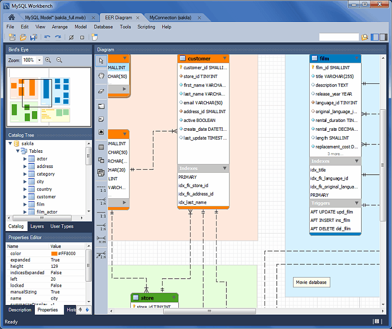
When the Model Editor is executed from the Home window, MySQL Workbench displays the MySQL Model page. The MySQL Model page has three main panels, as shown in the following screenshot: Description Editor, User Types List/History panel, and Model Overview.
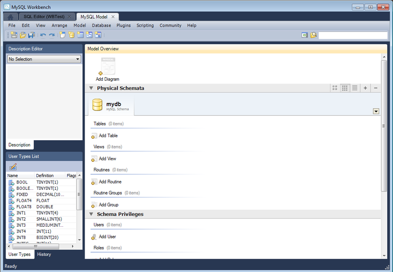
The Description Editor and User Types List/History panel are contained within the Sidebar. The Sidebar is located on the left by default, but can be relocated to the right using a setting in the Workbench Preferences dialog.
The Model Overview panel includes the following sections:
EER Diagrams
Physical Schemata
Schema Privileges
SQL Scripts
Model Notes
For each of these sections, add objects to a project by clicking the appropriate add-object icon. You may also rename, edit, cut, copy, or delete objects on this page by right-clicking to open a pop-up menu.
The following sections further discuss the MySQL Model page.
Some menu items are not available in the MySQL Workbench Community edition of this application, and are available only in MySQL Workbench Commercial. This is indicated where applicable.
Use the menu to open a project, begin a
new project, or save a project. Choosing opens the default schema,
mydb. Choosing opens a file dialog box with the default file
type set to MySQL Workbench Models (mwb
extension). To display a list of recently opened MWB files, choose
the menu item. The keyboard
shortcut to create a new project is Control+N and
the command to open an existing project is
Control+O.
To close the currently active MySQL Model or
EER Diagram tab, use the menu item. You can also do this from the
keyboard by pressing Control+W. To reopen the
MySQL Model tab, see
Section 9.1.1.1.3, “The View Menu”. To reopen an EER
Diagram tab, double-click the EER
Diagram icon in the EER Diagrams
section of the MySQL Model page.
Use the or menu items to save a model. When you save a
model, its name appears in the title bar of the application. If
you have made changes to a project and have not saved those
changes, an asterisk appears in the title bar following the model
name. When you save a model, it is saved as a MySQL Workbench file
with the extension mwb.
Use the menu item to import a
MySQL data definition (DDL) script file. For example, this might
be a file created by issuing the command mysqldump
--no-data. MySQL Workbench handles the
script as follows:
If the script does not contain a
CREATE DATABASEstatement, the schema objects are copied to the default schema,db_name;mydb.If the script creates a database, a new tab bearing the database name is added to the
Physical
          Schemata
section of theMySQL Modelpage.If the script contains data, the data is ignored.
For details about importing a DDL script, see Section 9.4.2.1, “Reverse Engineering Using a Create Script”.
Under the submenu, you can also
import DBDesigner4 files.
There are variety of items under the submenu. You may generate the SQL statements necessary to create a new database or alter an existing one. For more information about these menu items, see Section 9.4.1.1, “Forward Engineering Using an SQL Script”.
Using the submenu, you can also export an EER diagram as a PNG, SVG, PDF, or Postscript file. For an example of a PNG file, see Figure 9.29, “The sakila Database EER Diagram”.
The menu item enables you to set the paper size, orientation, and margins for printing purposes.
The printing options are enabled only if the EER Diagrams tab is selected. You have the choice of printing your model directly to your printer, printing it as a PDF file, or creating a PostScript file. For more information, see Section 9.2.1, “Printing Diagrams”.
The printing options are available only in commercial versions of MySQL Workbench.
Use the menu item to set the following properties of your project:
Name: The model name (default isMySQL Model)Version: The project version numberAuthor: The project authorProject: The project nameCreated: Not editable; determined by the MWB file attributesLast Changed: Not editable; determined by the MWB file attributesDescription: A description of your project
Use the menu to make changes to objects. The menu item text descriptions change to reflect the name of the selected object.
This menu has items for cutting, copying, and pasting. These actions can also be performed using the Control+X, Control+C, and Control+V key combinations. Undo a deletion using the item. The Control+Z key combination can also be used to undo an operation. It is also possible to carry out a operation using either the menu item, or the key combination Control+Y.
Also find a menu item for removing the currently selected object. The keyboard command for this action is Control+Delete. You can also right-click an object and choose the delete option from the pop-up menu.
The menu item behaves differently depending upon circumstances. For example, if an EER Diagram is active and a table on the canvas is the currently selected object, a dialog box may open asking whether you want to remove the table from the canvas only or from the database as well. For information about setting the default behavior when deleting from an EER Diagram, see Section 3.2.4, “Modeling Preferences”.
If the MySQL Model page is active, the
selected object is deleted from the catalog and there will be
no confirmation dialog box.
Choose to edit the currently selected object. You can also perform edits in a new window by selecting . The keyboard shortcuts for and are Control+E and Control+Shift+E, respectively.
The item has the following submenus:
(Keyboard shortcut, Control+A): Selects all the objects on the active EER diagram.
(Objects of the same type): Finds objects similar to the currently selected object.
: Finds all the objects connected to the currently selected object.
These menu items are active only when an EER Diagram tab is selected. The and the menu items are disabled if no object is currently selected on an EER diagram.
When multiple objects have been selected using one of these menu items, you can navigate between selected items by choosing the or menu item.
Selecting objects changes some of the menu items. If only one object is selected, that object's name appears after the , and menu items. If more than one object is selected, these menu items show the number of objects selected.
Each MySQL Workbench window includes search functionality. The panel with enabled is shown below:
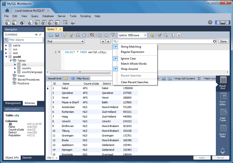
The Find dialogue options are described below:
(default) or : Search by matching a string, or a PCRE regular expression.
: A case-insensitive search. Works with both the and search methods. Enabled by default.
: If enabled, only whole strings are matched. For example, a search for "home" would not match "home_id". Disabled by default.
: The search will wrap around to the beginning of the document, as otherwise it will only search from the cursor position to the end of the document. Enabled by default.
And the arrows jump to the discovered search terms, and behave according to the option.
The MySQL Workbench Commercial edition includes an advanced Find facility for models:
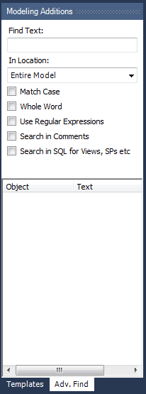
You can search the following locations:
Entire Model: Searches the entire model.
Current View: Searches the current view only. This may be the
MySQL Modelpage.All Views: Searches the
MySQL Model Pageand all EER diagrams.Database Objects: Searches database objects only.
Selected Figures: Searches the currently selected objects. This feature works only for EER diagrams.
Enter the text you wish to search for in the Find Text list. You may also select any or all of the following check boxes:
Match Case
Whole Word
Use Regular Expression
Search in Comments
Search in SQL for Views, SPs etc.
Any text you enter into the Find Text list is retained for the duration of your session. Use the or buttons to find occurrences of your search criterion.
Clicking the button opens a Find Results window anchored at the bottom of the application. If you wish, you may undock this window as you would any other.
Use this window to navigate to objects. For example,
double-clicking the Description of an object
located on an EER diagram navigates to the specific diagram and
selects the object. Notice that the properties of the object are
displayed in the Properties palette.
The Find dialog window can also be opened
using the Control+F key combination. Use
Control+G to find the next occurrence and
Control+Shift+G to find a previous occurrence.
Close the Find dialog window by clicking the
in the top right corner or by pressing
the Esc key.
This menu item enables you to set global preferences for the MySQL Workbench application.
For further information, see Section 3.2, “Workbench Preferences”.
This context-aware menu features general options for changing the view in MySQL Workbench. These options change depending on the current tab, and here are the available menu items:
General options:
: Selects the Home window
: Configure which of the three available panels are open. You may also manage this from the GUI using the panel toggle buttons on the top-right side of MySQL Workbench.
: Displays the console output.
: Selects the next (moves to the right, and wraps around) MySQL Workbench tab.
: Selects the previous (moves to the left, and wraps around) MySQL Workbench tab.
Model/EER options:
: A submenu with items that activate (slide open) specific panels. Designated panels include the "Model Navigator", "Catalog", "Layers", "User Datatypes", "Object Descriptions", "Object Properties", and "Undo History".
: The default level of detail of an EER diagram
: Zooms in on an EER diagram.
: Zooms out from an EER diagram.
The ability to zoom in on an EER diagram is also available using the slider tool in the
Model
          Navigator
palette. See Section 9.1.1.9, “The Model Navigator Panel”.: Bookmarks an object. From the keyboard, select the object you wish to bookmark, then use the key combination Control+Shift and the number of the marker (1 through 9). You may create up to nine markers.
: Returns to a marker. From the keyboard, use the Control key and the number of the marker.
: Displays grid lines on an EER diagram.
: Toggles Page Guides to help design the EER diagram on a per-page basis.
The menu items apply only to objects on an EER diagram canvas and are enabled only if an EER diagram view is active. The menu has these items:
: Aligns items on the canvas to the grid lines
: Brings objects to the foreground
: Sends objects to the background
: Centers objects on the canvas
: Automatically arranges objects on the canvas
: Expands an object on an EER diagram. For example, if a table has a long column name that is not fully displayed, this menu item expands the table to make the column visible. This menu item is not enabled unless an object is selected.
: Use this item to expand all objects on an EER diagram. This item will display a table's columns if the object notation supports expansion. Some object notations, such as
Classic, do not permit expansion or contraction. Indexes will not automatically be expanded unless they were previously expanded and have been collapsed using the menu item.: Undo the operation performed by .
When a model is opened, this menu features actions to perform against your model, and the menu has these items:
: Creates a new EER Diagram. The keyboard shortcut is Control+T.
: Creates an EER diagram from all the objects in the catalog.
: Presents a dialog box that enables you to add and delete user defined data types.
: For information about this menu item, see Section 9.1.1.1.5.1, “The DBDoc Model Reporting Dialog Window (Commercial Version)”. Commercial version only.
: Checks the validity of the model using ANSI standards. For information about this menu item, see Section 9.1.1.1.5.2, “The Validation Submenus (Commercial Version)”. Commercial version only.
: Checks the validity of the model using MySQL standards. For information about this menu item, see Section 9.1.1.1.5.2, “The Validation Submenus (Commercial Version)”. Commercial version only.
: For information about this menu item, see Section 9.1.1.1.5.3, “The Object Notation Submenu”.
: For information about this menu item, see Section 9.1.1.1.5.4, “The Relationship Notation Submenu”.
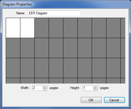
: Opens a diagram size dialog box that enables you to adjust the width or height of the canvas. The unit of measure is pages; the default value is two.
When you have tables with numerous columns, use this menu item to increase the size of the EER.
: Sets options at the model level. These options should not be confused with the options that are set globally for the Workbench application, and which are referred to as Workbench Preferences. The available model options are a subset of the Workbench Preferences options.
For more information about Workbench Preferences, see Section 3.2.4, “Modeling Preferences”.
This dialog window is found by navigating to the menu and choosing the item.
The item is not available in the MySQL Workbench Community version.
Use this dialog window to set the options for creating documentation of your database models. For more information, see Section 9.2.2, “DBDoc Model Reporting”.
The menu has two validation submenus, and . Use these submenus for general validation and MySQL-specific validation of the objects and relationships defined in your model.
These items are not available in the MySQL Workbench Community version.
The submenu has these items:
: Performs all available validation checks
: Checks for objects with no content, such as a table with no columns
: Checks the efficiency of tables, such as a table with no primary key defined
: Checks for duplicate identifiers, such as two tables with the same name
: Checks for consistent naming conventions
: Checks, for example, that a foreign key does not reference a nonprimary key column in the source table
The submenu has these items:
: Performs all available validation checks
: Checks for invalid references, such as a table name longer than the maximum permitted
: Checks for correct SQL syntax
: Checks for objects with the same name
For detailed information about validation, see Section 9.2.3, “Schema Validation Plugins”.
The items under the , submenu apply exclusively to an EER diagram. They are not enabled unless an EER diagram tab is selected.
The submenu has these items:
: Displays table columns, indexes, and triggers
: Shows only a table's columns
: Similar to the
Workbench (Simplified)style showing only the table's columns: The ICAM DEFinition language information modeling style
The object notation style that you choose persists for the duration of your MySQL Workbench session and is saved along with your model. When MySQL Workbench is restarted, the object notation reverts to the default.
If you plan to export or print an EER diagram be sure to decide on a notation style first. Changing notation styles after objects have been placed on a diagram can significantly change the appearance of the diagram.
The items under the submenu apply exclusively to an EER diagram. They are not enabled unless an EER diagram tab is selected.
The submenu has these items:
: The default modeling style. For an example, see Figure 9.24, “Adding Tables to the Canvas”.
: Uses a diamond shape to indicate cardinality.
: Universal Modeling Language style.
: The ICAM DEFinition language information modeling method
To view the different styles, set up a relationship between two or more tables and choose the different menu items.
The relationship notation style that you choose persists for the
duration of your MySQL Workbench session and is saved along with
your model. When MySQL Workbench is restarted, the relationship
notation reverts to the default, the Crow's
Foot style.
If you plan to export or print an EER diagram, be sure to decide on a notation style first. Changing notation styles after objects have been placed on a diagram can significantly change the appearance of the diagram.
This menu features actions against the connected MySQL server. The menu has these items:
: Launches the SQL Editor, which enables you to create SQL code and execute it on a live server. For more information, see Section 8.1, “Visual SQL Editor”.
: Launches the Manage Server Connections dialog, which enables you to create and manage multiple connections. For more information, see Section 5.3, “Manage Server Connections”
: Creates a model from an existing database. For more information, see Section 9.4.2.2, “Reverse Engineering a Live Database”.
: Creates a database from a model. For more information, see Section 9.4.1.2, “Forward Engineering to a Live Server”.
: Executes the database migration wizard for MySQL databases. It is useful for moving from an older MySQL server to the latest MySQL version, and is meant for local development purposes. You should not use this tool on production MySQL instances as they often require more complex data migration techniques.
For additional information about this wizard, see MySQL Schema Transfer Wizard.
: Executes the database migration wizard for most any database, and is meant to migrate tables and data from supported database systems to your MySQL server. For additional information, see Chapter 10, Database Migration Wizard.
: From here you can define custom type mappings, such as migrating the source data type
int8to the target MySQL data typeBIGINT.: Synchronizes your database model with an existing database. For more information, see Section 9.5.1, “Database Synchronization”.
: Allows you to compare a target database or script with the open model, external script, or a second database, and apply these changes back to the target. For more information, see Section 9.5.1, “Database Synchronization”.
: Compares your schema model with a live database or a script file. Section 9.5.2, “Compare and Report Differences in Catalogs”.
The menu lists tools and utilities that related to MySQL Workbench usage.
: Launches a file browser to open a specific audit log file. MySQL Workbench prompts for sudo access if the MySQL Workbench user is unable to read the audit log file. For additional information about the Audit Inspector, see Section 6.6, “MySQL Audit Inspector Interface”. Commercial only.
: Backup (or restore) your MySQL Connections, as defined in MySQL Workbench. Connection data is stored in a
connections.xmlfile, for additional information about this file, see Section 3.3, “MySQL Workbench Settings and Log Files”.: These utilities generate PHP code to either "Connect to the MySQL server" or "Iterate SELECT results", if applicable. For additional information about PHP code generation, see Section 8.1.12.2, “Generating PHP Code”.
: Opens the mysqluc MySQL Utility. For additional information about MySQL Utilities, see Appendix F, MySQL Utilities.
This menu features GRT scripting and plugin options. The menu has these items:
: Launches the MySQL Workbench Scripting Shell. For additional information, see Section C.5, “The Workbench Scripting Shell”.
: Opens a New Script File dialogue, with options to create a , , or .
: Opens a Open GRT Script dialogue, which defaults to the Workbench scripts directory. Files are opened into the Workbench Scripting Shell window.
: Executes the script that is currently open.
: Executes the specified script file.
: Loads and installs a plugin or module file
: Displays information about the plugins that are installed, and allows disabling and uninstalling the plugins.
Use the menu when you require support, or when you want to help improve MySQL Workbench. This menu has the following items:
: Opens a window showing a local copy of the MySQL Workbench documentation. Read, search, or print the documentation from this window.
: Opens your default browser on the MySQL Web site home page.
: Opens your default browser on the MySQL Workbench product page.
: Displays information about your system, which is useful when reporting a bug. For more information, see Section 9.1.1.1.9.1, “System Info”.
: Opens your default browser to bugs.mysql.com, and automatically fills in several fields such as the Operating System and MySQL Workbench version by passing in additional data via the GET request. The default "Description" requests you to also attach the Workbench log file. For additional information about reporting useful bug reports, see Appendix D, How To Report Bugs or Problems.
: Opens your default browser to see a list of current bugs.
: Opens up the directory that contains the MySQL Workbench log files.
: Opens up the main MySQL Workbench log file in your default text editor. This file is typically named
wb.log.: Checks if you are using the current MySQL Workbench version. If you are, then a popup informs you of this. If not, then a prompt asks you to open the MySQL Workbench download page.
: Displays the MySQL Workbench
Aboutwindow. This also displays the MySQL Workbench version.
Use the , menu item to display information about your system. This item is especially useful for determining your rendering mode. Sample output follows.
MySQL Workbench Community (GPL) for Windows version 6.1.4  revision 11773 build 1454
Configuration Directory: C:\Users\philip\AppData\Roaming\MySQL\Workbench
Data Directory: C:\Users\philip\Desktop\MySQL\MySQL Workbench 6.1.4 CE
Cairo Version: 1.8.8
OS: Microsoft Windows 7  Service Pack 1 (build 7601), 64-bit
CPU: 4x Intel(R) Core(TM) i5-2400 CPU @ 3.10GHz, 8.0 GiB RAM
Active video adapter NVIDIA GeForce GT 610
Installed video RAM: 1024 MB
Current video mode: 1920 x 1080 x 4294967296 colors
Used bit depth: 32
Driver version: 9.18.13.2049
Installed display drivers: nvd3dumx.dll,nvwgf2umx.dll,nvwgf2umx.dll,nvd3dum,nvwgf2um,nvwgf2um
Current user language: English (United States)
The MySQL Workbench toolbar is located immediately below the menu bar. Click the tools in the toolbar to perform the following actions:
The new document icon: Creates a new document
The folder icon: Opens a MySQL Workbench file (
mwbextension)The save icon: Saves the current MySQL Workbench project
The right and left arrows: The left arrow performs an “Undo” operation. The right arrow performs a “Redo” operation.
Other tools appear on the toolbar depending upon the context.
When an EER diagram canvas is selected, the following icons appear to the right of the arrow icons:
The toggle grid icon: Turns the grid on and off
The grid icon: Aligns objects on the canvas with the grid
The new EER diagram icon: Creates a new EER diagram tab.
The toolbar also changes depending upon which tool from the vertical toolbar is active. For discussion of these tools, see Section 9.1.2.1, “The Vertical Toolbar”.
If the Table tool is active, schemata lists,
engine types, and collations appear on the toolbar. The table
properties can be modified using the Properties Editor.
When an object is selected, the object's properties, such as color, can be changed in the Properties Editor.
Use the Add new Diagram icon in the
MySQL Model area to create EER diagrams. When
you add an EER diagram, a new tab appears below the toolbar. Use
this tab to navigate to the newly created EER diagram. For further
discussion of EER Diagrams, see
Section 9.1.2, “EER Diagram Editor”.
The Physical Schemata panel of the
MySQL Model page shows the active schemata and
the objects that they contain.
Expand and contract the Physical Schemata
section by double-clicking the arrow on the left of the
Physical Schemata title bar. When the
Physical Schemata section is expanded, it
displays all currently loaded schemata.
Each schema shows as a tab. To select a specific schema, click its
tab. When MySQL Workbench is first opened, a default schema,
mydb, is selected. You can start working with
this schema or you can load a new MySQL Workbench Model file (models
use the .mwb extension.)
There are a variety of ways to add schema to the Physical
Schemata panel. You can open an MWB file, reverse
engineer a MySQL create script, or, if you are using a commercial
version of MySQL Workbench, you can reverse engineer a database by
connecting to a MySQL server.
You can also add a new schema by clicking the
button on the top right of the
Physical Schemata panel. To remove a schema,
click its tab and use the button found to
the immediate left of the button. To the
left of these buttons are three buttons that control how database
object icons are displayed:
The left button displays database objects as large icons.
The middle button displays small icons in multiple rows.
The right button displays small icons in a single list.
The Physical Schemata panel has the following
sections:
Tables
Views
Routines
Routine Groups
Each section contains the specified database objects and an icon used for creating additional objects.
Any database objects added to an EER diagram canvas also show up
in the Physical Schemata section. For
information about adding objects to an EER diagram canvas, see
Section 9.1.2, “EER Diagram Editor”.
The Schema Privileges panel has the following
sections, used to create users for your schemata and to define
roles —:
Users
Roles
The following image displays the Schema
Privileges section of the MySQL Model
tab.
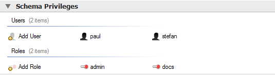
To add a role, double-click the Add Role
icon. This creates a role with the default name
role1. Right-clicking a role opens a pop-up
menu with the following items:
: Cuts the role
: Copies the role
: Opens the role editor
: Opens the role editor in a new editor window
: Removes the role
: Currently not implemented
To rename a role, click the role name. Then you will be able to edit the text.
All defined roles are listed under Roles on the left side of the role editor. Double-clicking a role object opens the role editor docked at the bottom of the page.
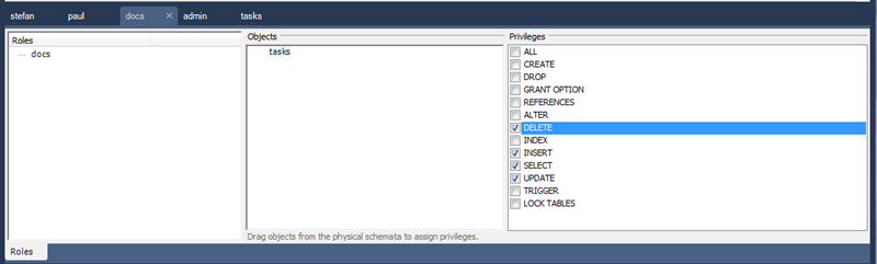
Select the role to which you wish to add objects. You may drag
and drop objects from the Physical Schemata
to the Objects section of the role editor. To
assign privileges to a role, select it from the
Roles section, then select an object in the
Objects section. In the
Privileges section, check the rights you wish
to assign to this role. For example, a
web_user role might have only
SELECT privileges and only for database
objects exposed through a web interface. Creating roles can make
the process of assigning rights to new users much easier.
To add a user, double-click the Add User
icon. This creates a user with the default name
user1. Double-clicking this user opens the
user editor docked at the bottom of the application.
In the User Editor, set the user's name and
password using the Name and
Password fields. Assign one role or a
number of roles to the user by selecting the desired roles from
the field on the right and then clicking the
button. Roles may be revoked by
moving them in the opposite direction.
Right-clicking a user opens a pop-up menu. The items in the menu function as described in Section 9.1.1.5.1, “Adding Roles”.
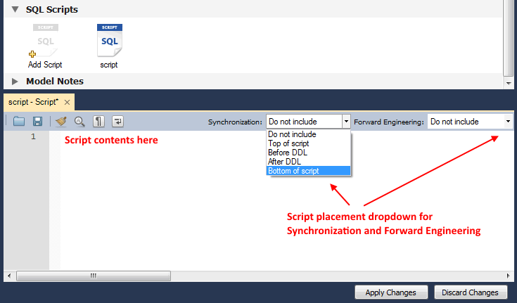
Use the SQL Scripts panel to attach SQL scripts
to the model for documentation and organizational purposes, and
optionally these attachments can be included in the output script
when performing forward engineering or model/schema
synchronization.
If you created your project from an SQL script and plan to create
an ALTER script, you may want to add the
original script here, since it will be needed to create an
ALTER script. For more information, see
Section 9.4.1.1.2, “Altering a Schema”.
The ability to use the attachments when performing forward engineering and synchronization was added in MySQL Workbench 6.2.0.
Use the Model Notes panel to write project
notes. Any scripts or notes added will be saved with your project.
Use the History palette to review the actions
that you have taken. Left-clicking an entry opens a pop-up menu
with the item, . Choose this item to select a single
entry. You can select multiple contiguous entries by pressing the
Shift key and clicking the entries you wish to
copy. Select noncontiguous entries by using the
Control key.
Only actions that alter the MySQL model or change an EER diagram
are captured by the History palette.
Docked at the top left of the application is the Model Navigator, or Bird's Eye panel. This panel provides an overview of the objects placed on an EER diagram canvas and for this reason it is most useful when an EER diagram is active. Any objects that you have placed on the canvas should be visible in the navigator.
The Model Navigator shows the total area of an EER diagram. A black rectangular outline indicates the view port onto the visible area of the canvas. To change the view port of an EER diagram, left-click this black outline and drag it to the desired location. You can zoom in on selected areas of an EER diagram by using the slider tool at the bottom of this window. The dimensions of the view port change as you zoom in and out. If the slider tool has the focus, you can also zoom using the arrow keys.
The default size of the Model Navigator is two
pages. Use the , page to change the size and
diagram name.
The Catalog Tree palette shows all the schemata
that are present in the Physical Schemata
section of the MySQL Model page. Expand the
view of the objects contained in a specific schema by clicking the
button to the left of the schema name.
This displays the following folder icons:
Tables
Views
Routine Groups
Expand each of these in turn by clicking the button to the left of the folder icon.
The Catalog Tree palette is primarily used to drag and drop objects onto an EER diagram canvas.
You can toggle the sidebar on and off using the Toggle Sidebar button, which is located in the top right of the application.
This palette shows all of the layers and figures on an EER
diagram. If a layer or figure is currently selected, an
X appears beside the name of the object and its
properties are displayed in the Properties
palette. This is useful when determining the selected objects
multiple objects were selected using the options under the
menu item. For more information
on this topic, see Section 9.1.1.1.2, “The Edit Menu”.
Selecting an object in the Layers palette also
adjusts the view port to the area of the canvas where the object
is located.
In some circumstances, you may want to make an object on an EER
diagram invisible. Select the object and, in the
Properties palette, set the
visible property to False.
The Layer palette provides an easy way to
locate an object, such as a relationship, that has been set to
hidden. Open the Layers
palette and select the object by double-clicking it. You can
then edit the object and change its visibility setting to
Fully Visible.
The Properties palette is used to display and
edit the properties of objects on an EER diagram. It is especially
useful for editing display objects such as layers and notes.
Selecting an object in the EER diagram displays its properties in
the Properties palette.
All objects except connections have the following properties except as noted:
color: The color accent of the object, displayed as a hexadecimal value. Change the color of the object by changing this value. Only characters that are legal for hexadecimal values may be entered. You can also change the color by clicking the button to open a color changing dialog box.description: Applicable to layers only. A means of documenting the purpose of a layer.expanded: This attribute applies to objects such as tables that can be expanded to show columns, indexes, and triggers.height: The height of the object. Depending upon the object, this property may be read only or read/write.left: The number of pixels from the object to the left side of the canvas.locked: Whether the object is locked. The value for this attribute is eithertrueorfalse.manualSizing: Whether the object was manually sized. The value for this attribute is eithertrueorfalse.name: The name of the object.top: The number of pixels from the object to the top of the canvas.visible: Whether the object shows up on the canvas. Use‘1’for true and‘0’for false. It is currently used only for relationships.width: The width of the object. Depending upon the object, this property may be read only or read/write.
Tables have the following additional properties:
indexesExpanded: Whether indexes are displayed when a table is placed on the canvas. Use‘1’for true and‘0’for false.triggersExpanded: Whether triggers are displayed when a table is placed on the canvas. Use‘1’for true and‘0’for false.
For a discussion of connection properties, see Section 9.1.4.3, “Connection Properties”.
EER diagrams are created by double-clicking the Add
Diagram icon. You may create any number of EER diagrams
just as you may create any number of physical schemata (databases).
Each EER diagram shows as a tab below the toolbar; a specific EER
diagram is selected by clicking its tab.
Clicking an EER diagram tab navigates to the canvas used for
graphically manipulating database objects. The Vertical
Toolbar is on the left side of this page.
This tool is for creating and editing EER diagrams for a model. To edit an existing database, either reverse engineer the database to create a model, or syncronize your model to a database. For additional information, see Section 9.4.2.2, “Reverse Engineering a Live Database” and Section 9.5, “Schema Synchronization and Comparison”.
The vertical toolbar shows on the left sidebar when an EER diagram tab is selected. The tools on this toolbar assist in creating EER diagrams.
Clicking a tool changes the mouse pointer to a pointer that resembles the tool icon, indicating which tool is active. These tools can also be activated from the keyboard by pressing the key associated with the tool. Hover the mouse pointer over a toolbar icon to display a description of the tool and its shortcut key.
A more detailed description of each of these tools follows.
The standard mouse pointer, located at the top of the vertical toolbar, is the default mouse pointer for your operating system. Use this tool to revert to the standard mouse pointer after using other tools.
To revert to the default pointer from the keyboard, use the Esc key.
The hand tool is used to move the entire EER diagram. Left-click on this tool and then left-click anywhere on the EER diagram canvas. Moving the mouse while holding down the mouse button changes the view port of the canvas.
To determine your position on the canvas, look at the
Model Navigator panel on the upper right. If
the Model Navigator panel is not open, use
, ,
to open it.
To activate the hand tool from the keyboard, use the H key.
You can also change the view port of an EER diagram using the
Model Navigator panel. See
Section 9.1.1.9, “The Model Navigator Panel”.
Use the eraser tool to delete objects from the EER Diagram canvas. Change the mouse pointer to the eraser tool, then click the object you wish to delete. Depending upon your settings, the delete dialog box should open, asking you to confirm the type of deletion.
The delete action of the eraser tool is
controlled by the general option setting for deletion. Before
using the eraser tool, be sure that you understand the
available options described in
Section 3.2.4, “Modeling Preferences”.
To activate the eraser tool from the keyboard, use the D key.
You can also delete an object by selecting it and pressing Control+Delete or by right-clicking it and choosing from the pop up menu.
The layer tool is the rectangular icon with a capital
L in the lower left corner. Use the layer
tool to organize the objects on an EER Diagram canvas. It is
useful for grouping similar objects. For example, you may use it
to group all your views.
Click the layer tool and use it to draw a rectangle on the canvas. Change to the standard mouse pointer tool and pick up any objects you would like to place on the newly created layer.
To change the size of a layer, first select it by clicking it. When a layer is selected, small rectangles appear at each corner and in the middle of each side. Adjust the size by dragging any of these rectangles.
You can also make changes to a layer by selecting the layer and
changing properties in the Properties panel.
Using the Properties panel is the only way to
change the name of a layer.
To activate the layer tool from the keyboard, use the L key. For more information about layers, see Section 9.1.7, “Creating Layers”.
The text tool is the square icon with a capital
N in the top left corner. Use this tool to
place text objects on the EER diagram canvas. Click the tool,
then click the desired location on the canvas. After a text
object has been dropped on the canvas, the mouse pointer reverts
to its default.
To add text to a text object, right-click the text object and choose or from the pop-up menu.
You can manipulate the properties of a text object by selecting
it and then changing its properties in the
Properties panel.
To activate the text tool from the keyboard, use the N key. For more information about text objects, see Section 9.1.9, “Creating Text Objects”.
Use the image tool to place an image on the canvas. When this tool is selected and you click the canvas, a dialog box opens enabling you to select the desired graphic file.
To activate the image tool from the keyboard, use the I key. For more information about images, see Section 9.1.10, “Creating Images”.
Use this tool to create a table on the EER Diagram canvas.
Clicking the canvas creates a table. To edit the table with MySQL Table Editor, right-click it and choose or from the pop-up menu. You can also double-click the table to load it into the table editor.
To activate the table tool from the keyboard, use the T key.
For more information about creating and editing tables, see Section 8.1.11, “The MySQL Table Editor”.
Use this tool to create a view on an EER Diagram canvas. When the table tool is activated, a schema list appears on the toolbar below the main menu, enabling you to associate the new view with a specific schema. You can also select a color for the object by choosing from the color list to the right of the schema list.
After selecting this tool, clicking the canvas creates a new view. To edit this view, right-click it and choose or from the pop-up menu.
To activate the view tool from the keyboard, use the V key.
For more information about creating and editing views, see Section 9.1.5, “Creating Views”.
Use this tool to create a routine group on the EER Diagram canvas. When this tool is activated, a schema list appears on the toolbar below the main menu, enabling you to associate the routine group with a specific schema. You can also select a color for the routine group by choosing from the color list to the right of the schema list.
After selecting this tool, clicking the canvas creates a new group. To edit this view, right-click it and choose or from the pop-up menu.
To activate the routine group tool from the keyboard, use the G key.
For more information about creating and editing routine groups, see Section 9.1.6.2, “Routine Groups”.
The five relationship tools are used to represent the following relationships:
One-to-many nonidentifying relationships
One-to-one nonidentifying relationships
One-to-many identifying relationships
One-to-one identifying relationships
Many-to-many identifying relationships
These tools appear at the bottom of the vertical tool bar. Hover the mouse pointer over each tool to see a text hint that describes its function.
For more information about relationships, see Section 9.1.4, “Creating Foreign Key Relationships”.
Double-clicking the Add table icon in the
Physical Schemata section of the MySQL
Model page adds a table with the default name of
table1. If a table with this name already
exists, the new table is named table2.
Adding a new table automatically opens the table editor docked at the bottom of the application. For information about using the table editor, see Section 8.1.11, “The MySQL Table Editor”.
Right-clicking a table opens a context menu with the following items:
: Cut a table to optionally paste it into another schema.
: Copy a table to optionally paste it into another schema.
: Paste a cut or copied table. The Paste option is also accessable from the main menu.
: Changes the docked table editor to the selected table.
: Opens the table in a new table editor tab.
: Copies a
CREATE TABLEstatement for the table.: Copies a comma-separated list of column names.
: Copies
INSERTstatements based on the model's inserts. Nothing is copied to the clipboard if the table has no inserts defined.: Copies a generic
INSERTstatement that is based on the model.: Remove a table from the database.
WarningThis immediately deletes the table without a confirmation dialog box.
If the table editor is not open, the item opens it. If it is already open, the selected table replaces the previous one. opens an additional table editor tab.
Any tables added to the Physical Schemata
section also show up in the Catalog palette on
the right side of the application. They may be added to an EER
Diagram by dragging and dropping them from this palette.
Tables can also be added to an EER Diagram using the
table tool on the vertical toolbar. Make sure
that the EER Diagram tab is selected, then
right-click the table icon on the vertical toolbar. The table icon
is the rectangular tabular icon.
Clicking the mouse on this icon changes the mouse pointer to a table pointer. You can also change the mouse pointer to a table pointer by pressing the T key.
Choosing the table tool changes the contents of
the toolbar that appears immediately below the menu bar. When the
Tables pointer is active, this toolbar contains
a schemata list, an engines list, a collations list, and a color
chart list. Use these lists to select the appropriate schema,
engine, collation, and color accent for the new table. Make sure
that you associate the new table with a database. The engine and
collation of a table can be changed using the table editor. The
color of your table can be changed using the
Properties palette. The Default
Engine and Default Collation values
refer to the database defaults.
Create a table by clicking anywhere on the EER Diagram canvas.
This creates a new table with the default name
table1. To revert to the default mouse pointer,
click the arrow icon at the top of the vertical toolbar.
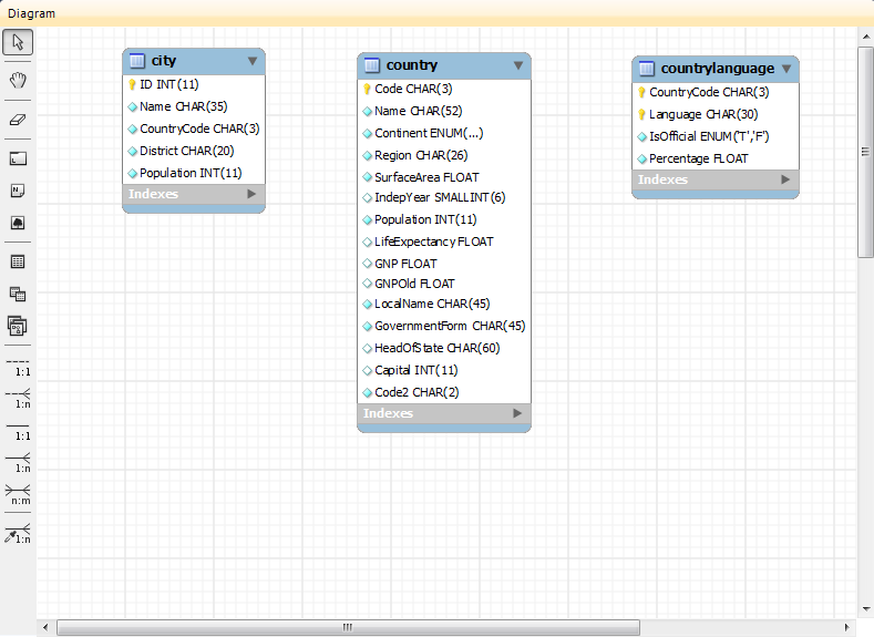
As shown in the preceding diagram, the primary key is indicated by a key icon and indexed fields are indicated by a different colored diamond icon. Click the arrow to the right of the table name to toggle the display of the fields. Toggle the display of indexes and triggers in the same way.
Right-clicking a table opens a pop-up menu with the following items:
With the exception of the deletion item, these menu items function as described in Section 9.1.3.1, “Adding Tables to the Physical Schemata”. The behavior of the delete option is determined by your MySQL Workbench options settings. For more information, see Section 3.2.4, “Modeling Preferences”.
Foreign key constraints are supported for the
InnoDB storage engine only. For other storage
engines, the foreign key syntax is correctly parsed but not
implemented. For more information, see
Foreign Key Differences.
Using MySQL Workbench you may add a foreign key from within the table editor or by using the relationship tools on the vertical toolbar of an EER Diagram. This section deals with adding a foreign key using the foreign key tools. To add a foreign key using the table editor, see Section 8.1.11.4, “The Foreign Keys Tab”.
The graphical tools for adding foreign keys are most effective when you are building tables from the ground up. If you have imported a database using an SQL script and need not add columns to your tables, you may find it more effective to define foreign keys using the table editor.
The vertical toolbar on the left side of an EER Diagram has six foreign key tools:
one-to-one non-identifying relationshipone-to-many non-identifying relationshipone-to-one identifying relationshipone-to-many identifying relationshipmany-to-many identifying relationshipPlace a Relationship Using Existing Columns
Differences include:
An identifying relationship: identified by a solid line between tables
An identifying relationship is one where the child table cannot be uniquely identified without its parent. Typically this occurs where an intermediary table is created to resolve a many-to-many relationship. In such cases, the primary key is usually a composite key made up of the primary keys from the two original tables.
A non-identifying relationship: identified by a broken (dashed) line between tables
Create or drag and drop the tables that you wish to connect.
Ensure that there is a primary key in the table that will be on
the “one” side of the relationship. Click on the
appropriate tool for the type of relationship you wish to create.
If you are creating a one-to-many relationship, first click the
table that is on the “many” side of the relationship,
then on the table containing the referenced key. This creates a
column in the table on the many side of the relationship. The
default name of this column is
table_name_key_name where the table
name and the key name both refer to the table containing the
referenced key.
When the many-to-many tool is active, double-clicking a table creates an associative table with a many-to-many relationship. For this tool to function there must be a primary key defined in the initial table.
Use the menu, menu item to set a project-specific default name for the foreign key column (see Section 9.1.1.1.5.4, “The Relationship Notation Submenu”). To change the global default, see Section 3.2.4, “Modeling Preferences”.
To edit the properties of a foreign key, double-click anywhere on the connection line that joins the two tables. This opens the relationship editor.
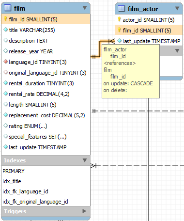
Mousing over a relationship connector highlights the connector and
the related keys as shown in the following figure. The
film and the film_actor
tables are related on the film_id field and
these fields are highlighted in both tables. Since the
film_id field is part of the primary key in the
film_actor table, a solid line is used for the
connector between the two tables. After mousing over a
relationship for a second, a yellow box is displayed that provides
additional information.
If the placement of a connection's caption is not suitable, you
can change its position by dragging it to a different location. If
you have set a secondary caption, its position can also be
changed. For more information about secondary captions, see
Section 9.1.4.3, “Connection Properties”. Where the notation
style permits, Classic for example, the
cardinality indicators can also be repositioned.
The relationship notation style in Figure 9.11, “The Relationship Connector” is the default, crow's foot. You can change this if you are using a commercial version of MySQL Workbench. For more information, see Section 9.1.1.1.5.4, “The Relationship Notation Submenu”.
You can select multiple connections by holding down the Control key as you click a connection. This can be useful for highlighting specific relationships on an EER diagram.
Double-clicking a relationship on the EER diagram canvas opens the relationship editor. This has two tabs: Relationship, and Foreign Key.
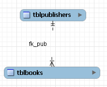
The Relationship Tab
In the Relationship tab, you can set the
caption of a relationship using the Caption
field. This name displays on the canvas and is also the name used
for the constraint itself. The default value for this name is
fk_.
Use the menu, menu item to set a project-specific default
name for foreign keys. To change the global default, see
Section 3.2.4, “Modeling Preferences”.
source_table_destination_table
You can also add a secondary caption and a caption to a relationship.
The Visibility Settings section is used to
determine how the relationship is displayed on the EER Diagram
canvas. Fully Visible is the default but you
can also choose to hide relationship lines or to use split lines.
The split line style is pictured in the following figure.
A broken line connector indicates a nonidentifying relationship. The split line style can be used with either an identifying relationship or a nonidentifying relationship. It is used for display purposes only and does not indicate anything about the nature of a relationship.
To set the notation of a relationship use the menu, menu item. For more information, see Section 9.1.1.1.5.4, “The Relationship Notation Submenu”.
The Foreign Key Tab
The Foreign Key tab contains several sections: Referencing Table, Cardinality and Referenced Table.
The Mandatory check boxes are used to select
whether the referencing table and the referenced table are
mandatory. By default, both of these constraints are
true (indicated by the check boxes being
checked).
The Cardinality section has a set of radio buttons that enable you to choose whether the relationship is one-to-one or one-to-many. There is also a check box that enables you to specify whether the relationship is an identifying relationship.
Right-click a connection to select it. When a connection is selected, it is highlighted and its properties are displayed in the properties palette. Connection properties are different from the properties of other objects. The following list describes them:
caption: The name of the connection. By default, the name is the name of the foreign key and the property is centered above the connection line.captionXOffs: The X offset of the caption.captionYOffs: The Y offset of the caption.comment: The comment associated with the relationship.drawSplit: Whether to show the relationship as a continuous line.endCaptionXOffs: The X termination point of the caption offset.endCaptionYOffs: The Y termination point of the caption offset.extraCaption: A secondary caption. By default, this extra caption is centered beneath the connection line.extraCaptionXOffs: The X offset of the secondary caption.extraCaptionYOffs: The Y offset of the secondary caption.mandatory: Whether the entities are mandatory. For more information, see Section 9.1.4.2, “The Relationship Editor”.many: False if the relationship is a one-to-one relationship.middleSegmentOffset: The offset of the middle section of the connector.modelOnly: Set when the connection will not be propagated to the DDL. It is just a logical connection drawn on a diagram. This is used, for example, when drawingMyISAMtables with a visual relationship, but with no foreign keys.name: The name used to identify the connection on the EER Diagram canvas. Note that this is not the name of the foreign key.referredMandatory: Whether the referred entity is mandatory.startCaptionXOffs: The start of the X offset of the caption.startCaptionYOffs: The start of the Y offset of the caption.
In most cases, you can change the properties of a relationship
using the relationship editor rather than the
Properties palette.
If you make a relationship invisible by hiding it using the relationship editor's Visibility Settings, and then close the relationship editor, you will no longer be able to select the relationship to bring up its relationship editor. To make the relationship visible again, you must expand the table object relating to the relationship in the Layers palette and select the relationship object. To edit the selected object, right-click it, then select . You can then set the Visibility Settings to Fully Visible. The relationship will then be visible in the EER Diagram window.
You can add views to a database either from the Physical
Schemata section of the MySQL Model
page or from the EER Diagram.
To add a view, double-clicking the Add View
icon in the Physical Schemata section of the
MySQL Model page. The default name of the view
is view1. If a view with this name already
exists, the new view is named view2.
Adding a new view automatically opens the view editor docked at the bottom of the application. For information about using the view editor, see Section 9.1.5.3, “The View Editor”.
Right-clicking a view opens a pop-up menu with the following items:
The '
view_name' is only cut from the EER canvas, and not removed from the schema.: deletes from both the EER canvas and schema.
: deletes from the EER canvas, but not the schema.
If the table editor is not open, the item opens it. If it is already open, the selected table replaces the previous one. opens a new view editor tab.
The cut and copy items are useful for copying views between
different schemata. copies the CREATE VIEW
statement to the clipboard.
Use the item to remove a view from the database. There will be no confirmation dialog box.
Any views added to the Physical Schemata
section also show up in the Catalog palette on
the left side of the application. They may be added to an EER
Diagram, when in the EER Diagram tab, by dragging and dropping
them from this palette.
Views can also be added to an EER Diagram using the
View tool on the vertical toolbar. Make sure
that the EER Diagram tab is selected, then
left-click the view icon on the vertical toolbar. The view icon is
the two overlapping rectangles found below the table icon.
Clicking this icon changes the mouse pointer to a view pointer. To change the mouse pointer to a view pointer from the keyboard, use the V key.
Choosing the View tool changes the contents of
the toolbar that appears immediately below the main menu bar. When
the Views pointer is active, this toolbar
contains a schemata list and a color chart list. Use these lists
to select the appropriate schema and color accent for the new
view. Make sure that you associate the new view with a database.
The color of your view can be changed using the
Properties palette.
Create a view by clicking anywhere on the EER Diagram canvas. This
creates a new view with the default name view1.
To revert to the default mouse pointer, click the arrow icon at
the top of the vertical toolbar.
Right-clicking a view opens a pop-up menu. With the exception of the delete item, these menu items function as described in Section 9.1.5.1, “Adding Views to the Physical Schemata”. The behavior of the delete option is determined by your MySQL Workbench options settings. For more information, see Section 3.2.4, “Modeling Preferences”.
To invoke the view editor, double-click a view object on the EER
Diagram canvas or double-click a view in the Physical
Schemata section on the MySQL Model
page. This opens the view editor docked at the bottom of the
application. Double-clicking the title bar undocks the editor. Do
the same to redock it. Any number of views may be open at the same
time. Each additional view appears as a tab at the top of the view
editor.
There are three tabs at the bottom of the view editor: View, Comments, and Privileges. Navigate between different tabs using the mouse or from the keyboard by pressing Control+Alt+Tab.
The View Tab
Use the View tab to perform the following tasks:
Rename the view using the Name text box.
Enter the SQL to create a view using the SQL field.
Comment a view using the Comments text area.
The Comments Tab
This tab enables you to enter comments for a particular view.
The Privileges Tab
The Privileges tab of the view editor functions in exactly the same way as the Privileges tab of the routine editor. For more information, see Section 9.1.6.1.2.2, “The Privileges Tab”.
When you select a view on the EER Diagram canvas, its properties
are displayed in the Properties palette. Most
of the properties accessible from the
Properties palette apply to the appearance of a
view on the EER Diagram canvas.
For a list of properties accessible through the
Properties palette, see
Section 9.1.1.12, “The Properties Palette”.
You can add Routine Groups to a database either from the Physical Schemata section of the MySQL Model page or from an EER Diagram. Routines may be added only from the Physical Schemata section of the MySQL Model page.
To view an existing schema, along with its Routines and Routine Groups, choose , from the main menu. After the schema has been added to the current model, you can see the schema objects on the Physical Schemata panel on the MySQL Model page. The Routines and Routine Groups are listed there.
MySQL Workbench unifies both stored procedures and stored functions into one logical object called a Routine. Routine Groups are used to group related routines. Define Routine with the Routine Group Editor to assign specific routines to a group, using a drag and drop interface.
When designing an EER Diagram, you can place the Routine Groups on the canvas by dragging them from the Catalog Palette. Placing individual routines on the diagram is not permitted, as it would clutter the canvas.
To add a routine, double-click the Add
Routine icon in the Physical
Schemata section of the MySQL Model
page. The default name of the routine is
routine1. If a routine with this name already
exists, the new routine is named routine2.
Adding a new routine automatically opens the routine editor docked at the bottom of the application. For information about using the routine editor, see Section 9.1.6.1.2, “The Routine Editor”.
Right-clicking a routine opens a pop-up menu with the following items:
The item opens the routine editor.
The cut and paste items are useful for copying routines between different schemata.
Deleting the code for a routine from the Routines tab of the Routine Group Editor results in removal of the routine object from the model.
To remove a routine from a routine group, use the controls on the Routine Group tab of the Routine Group Editor.
The action of the delete option varies depending upon how you have configured MySQL Workbench. For more information, see Section 3.2.4, “Modeling Preferences”.
To invoke the routine editor, double-click a routine in the
Physical Schemata section on the
MySQL Model page. This opens the routine
editor docked at the bottom of the application. Any number of
routines may be open at the same time. Each additional routine
appears as a tab at the top of the routine editor.
Routine and Privileges tabs appear at the bottom of the routine editor. Navigate between different tabs using the mouse or from the keyboard by pressing Control+Alt+Tab.
Use the Routine tab of the routine editor to perform the following tasks:
Rename the routine using the Name field.
Enter the SQL to create a routine using the SQL field.
The Privileges tab of the routine editor allows you to assign specific roles and privileges. You may also assign privileges to a role using the role editor. For a discussion of this topic, see Section 9.1.1.5.1, “Adding Roles”.
When this tab is first opened, all roles that have been created are displayed in the list on the right. Move the roles you wish to associate with this table to the Roles list on the left. Do this by selecting a role and then clicking the button. Use the Shift key to select multiple contiguous roles and the Control key to select noncontiguous roles.
To assign privileges to a role, click the role in the Roles list. This displays all available privileges in the Assigned Privileges list. The privileges that display are:
ALLCREATEDROPGRANT OPTIONREFERENCESALTERDELETEINDEXINSERTSELECTUPDATETRIGGER
You can choose to assign all privileges to a specific role or
any other privilege as listed previously. Privileges
irrelevant to a specific table, such as the
FILE privilege, are not shown.
If a role has already been granted privileges on a specific table, those privileges show as already checked in the Assigned Privileges list.
Double-clicking the Add Routine Group icon in
the Physical Schemata section of the
MySQL Model page adds a routine group with
the default name of routines1. If a routine
group with this name already exists, the new routine group is
named routines2.
Adding a new routine group automatically opens the routine groups editor docked at the bottom of the application. For information about using the routine groups editor, see Section 9.1.6.2.3, “The Routine Group Editor”.
Right-clicking a routine group opens a pop-up menu with the following items:
The item opens the routine group editor, which is described in Section 9.1.6.2.3, “The Routine Group Editor”.
The cut and paste items are useful for copying routine groups between different schemata.
Deleting a routine group from the MySQL Model
page removes the group but does not remove any routines
contained in that group.
Any routine groups added to the Physical
Schemata also show up in the
Catalog palette on the right side of the
application. They may be added to an EER diagram by dragging and
dropping them from this palette.
To add routine groups to an EER Diagram, use the
Routine Groups tool on the vertical toolbar.
Make sure that the EER Diagram tab is
selected, then right-click the routine groups icon on the
vertical toolbar. The routine groups icon is immediately above
the lowest toolbar separator.
Clicking the mouse on this icon changes the mouse pointer to a routine group pointer. You can also change the mouse pointer to a routine pointer by pressing the G key.
Choosing the Routine Group tool changes the
contents of the toolbar that appears immediately below the menu
bar. When the Routine Groups pointer is
active, this toolbar contains a schemata list and a color chart
list. Use these lists to select the appropriate schema and color
accent for the new routine group. Make sure that you associate
the new routine group with a database. The color of your routine
group can be changed later using the
Properties palette.
Create a routine group by clicking anywhere on the EER Diagram
canvas. This creates a new routine group with the default name
routines1. To revert to the default mouse
pointer, click the arrow icon at the top of the vertical
toolbar.
Right-clicking a routine group opens a pop-up menu. With the exception of the delete option and rename options, these menu options function as described in Section 9.1.6.2.1, “Adding Routine Groups to the Physical Schemata”. There is no rename option, and the behavior of the delete option is determined by your MySQL Workbench options settings. For more information, see Section 3.2.4, “Modeling Preferences”.
To invoke the routine group editor, double-click a routine group
object on the EER Diagram canvas or double-click a routine group
in the Physical Schemata section on the
MySQL Model page. This opens the routine
group editor docked at the bottom of the application.
Double-clicking the title bar undocks the editor. Do the same to
redock it. Any number of routine groups may be open at the same
time. Each additional routine group appears as a tab at the top
of the routine editor,
Routine group and Privileges tabs appear at the bottom of the routine editor. Navigate between different tabs using the mouse or from the keyboard by pressing Control+Alt+Tab.
Use the Routine Groups tab of the routine groups editor to perform the following tasks:
Rename the routine group using the Name field.
Add routines to the group by dragging and dropping them.
Add comments to the routine group.
The Privileges tab of the routine group editor functions in exactly the same way as the Privileges tab of the table editor. For more information, see Section 9.1.6.1.2.2, “The Privileges Tab”.
When you select a routine group on the EER Diagram canvas, its
properties are displayed in the Properties
palette. All of the properties accessible from the
Properties palette apply to the appearance
of a routine group on the EER Diagram canvas.
For a list of properties accessible through the
Properties palette, see
Section 9.1.1.12, “The Properties Palette”.
You can add layers to a database only from an EER Diagram. Layers are used to help organize objects on the canvas. Typically, related objects are added to the same layer; for example, you may choose to add all your views to one layer.
To add layers to an EER Diagram, use the Layer
tool on the vertical toolbar. Select an EER
Diagram tab and left-click the layer icon on the
vertical toolbar. The layer icon is the rectangle with an
‘L’ in the lower left corner and it
is found below the eraser icon.
Clicking the mouse on this icon changes the mouse pointer to a layer pointer. You can also change the mouse pointer to a layer pointer by pressing the L key.
Choosing the Layer tool changes the contents of
the toolbar that appears immediately below the menu bar. When the
Layers pointer is active, this toolbar contains
a color chart list. Use this list to select the color accent for
the new layer. The color of your layer can be changed later using
the Properties palette.
Create a layer by clicking anywhere on the EER Diagram canvas and,
while holding the left mouse button down, draw a rectangle of a
suitable size. This creates a new layer with the default name
layer1. To revert to the default mouse pointer,
click the arrow icon at the top of the vertical toolbar.
The following image shows a layer named "My Sakila Views" with several views:

To open the layer editor, either double-click the layer or right-click the layer and choose the edit option. The available context-menu options are:
A layer may also be edited via Properties Editor on the left panel, and it offers additional edit options.
The cut and copy items are useful for copying layers between different schemata.
Since layers are not schema objects, no confirmation dialog box opens when you delete a layer regardless of how you have configured MySQL Workbench. Deleting a layer does not delete schema objects from the catalog.
To add an object to a layer, drag and drop it directly from the
Catalog palette onto a layer. If you pick up
an object from an EER diagram, you must press
Control as you drag it onto the layer,
otherwise it will not be “locked” inside the layer.
Locking objects to a layer prevents their accidental removal. You cannot remove them by clicking and dragging; to remove an object, you also must press the Control key while dragging it.
As a visual cue that the object is being “locked”, the outline of the layer is highlighted as the object is dragged over it.
If you drag a layer over a table object, the table object will automatically be added to the layer. This also works for multiple table objects.
Layers cannot be nested. That is, a layer cannot contain another layer object.
Choosing "Edit" allows you to edit the layer name and layer background color, and the "Properties Editor" offers additional edit options.
When you select a layer on the EER Diagram canvas, its properties
are displayed in the Properties palette. The
properties accessible from the Properties
palette apply to the appearance of a layer on the EER Diagram
canvas.
In some circumstances, you may want to make a layer invisible.
Select the layer and, in the Properties
palette, set the visible property to
False. To locate an invisible object, open the
Layers palette and select the object by
double-clicking it. After an object is selected, you can reset the
visible property from the
Properties palette.
For a list of properties accessible through the
Properties palette, see
Section 9.1.1.12, “The Properties Palette”. In addition to the
properties listed there, a layer also has a
description property. Use this property to
document the purpose of the layer.
You can add notes to a database only from the Model
Notes section of the MySQL Model page.
Notes are typically used to help document the design process.
Double-clicking the Add Note icon in the
Model Notes section of the MySQL
Model page adds a note with the default name of
note1. If a note with this name already exists,
the new note is named note2.
Adding a new note automatically opens the note editor docked at the bottom of the application. For information about using the note editor, see Section 9.1.8.2, “The Note Editor”.
Right-clicking a note opens a pop-up menu with the following items:
The item opens the note editor. For information about using the note editor, see Section 9.1.8.2, “The Note Editor”.
The cut and copy items are useful for copying notes between different schemata.
Notes can be added only on the MySQL Model
page.
To invoke the note editor, double-click a note object in the
Model Note section on the MySQL
Model page. This opens the note editor docked at the
bottom of the application. Double-clicking the note tab undocks
the editor. Double-click the title bar to redock it. Any number of
notes may be open at the same time. Each additional note appears
as a tab at the top of the note editor.
Use the editor to change the name of a note or its contents.
Text objects are applicable only to an EER diagram. They can be used for documentation purposes; for example, to explain a grouping of schema objects. They are also useful for creating titles for an EER diagram should you decide to export a diagram as a PDF or PNG file.
To add text objects to an EER Diagram, use the Text
Object tool on the vertical toolbar. Make sure that the
EER Diagram tab is selected, then right-click
the text object icon on the vertical toolbar. The text object icon
is the rectangular icon found below the label icon.
Clicking the mouse on this icon changes the mouse pointer to a text object pointer. You can also change the mouse pointer to a text object pointer by pressing the N key.
Choosing the Text Object tool changes the
contents of the toolbar that appears immediately below the menu
bar. When the Text Object pointer is active,
this toolbar contains a color chart list. Use this list to select
the color accent for the new text object. The color of your text
object can be changed later using the
Properties palette.
Create a text object by clicking anywhere on the EER Diagram
canvas. This creates a new text object with the default name
text1. To revert to the default mouse pointer,
click the arrow icon at the top of the vertical toolbar.
Right-clicking a text object opens a pop-up menu. These menu options are identical to the options for other objects. However, since a text object is not a database object, there is no confirmation dialog box when you delete a text object.
To invoke the text object editor, double-click a text object on the EER Diagram canvas. This opens the editor docked at the bottom of the application. Double-clicking the text object table undocks the editor. Double-click the title bar to redock it. Any number of text objects may be open at the same time. Each additional text objects appears as a tab at the top of the text editor.
Use the editor to change the name of a text object or its contents.
When you select a text object on the EER Diagram canvas, its
properties are displayed in the Properties
palette. Most of the properties accessible from the
Properties palette apply to the appearance of
a view on the EER Diagram canvas.
For a list of properties accessible through the
Properties palette, see
Section 9.1.1.12, “The Properties Palette”.
There is no property in the Properties
palette for changing the font used by a text object. To do so,
choose the Appearance tab of the Workbench
Preferences dialog. For more information, see
Preferences: Modeling: Appearance.
Images exist only on the EER Diagram canvas; you can add them only from the EER Diagram window.
To add images to an EER Diagram, use the Image
tool on the vertical toolbar. Make sure that the EER
Diagram tab is selected, then right-click the image
icon on the vertical toolbar. The image icon is the icon just
above the table icon.
Clicking the mouse on this icon changes the mouse pointer to an image pointer. You can also change the mouse pointer to an image pointer by pressing the I key.
Create an image by clicking anywhere on the EER Diagram canvas. This opens a file open dialog box. Select the desired image, then close the dialog box to create an image on the canvas. To revert to the default mouse pointer, click the arrow icon at the top of the vertical toolbar.
Right-clicking this object opens a pop-up menu with the following items:
These menu items function in exactly the same way as they do for other objects on an EER diagram. However, images are not database objects so there is no confirmation dialog box when they are deleted.
To invoke the image editor, double-click an image object on an EER Diagram canvas. This opens the image editor docked at the bottom of the application. Double-clicking the image editor tab undocks the editor. Double-click the title bar to redock it. Any number of images may be open at the same time. Each additional image appears as a tab at the top of the image editor.
Additional modeling design tools and features.
The printing options used to create printouts of your EER Diagrams are found under the menu. To create documentation of your models, see Section 9.1.1.1.5.1, “The DBDoc Model Reporting Dialog Window (Commercial Version)”.
The printing menu items not enabled unless an EER Diagram is active. These items are available:
Enables you to choose the paper size, orientation, and margins.
Sends your EER Diagram directly to the printer. This option generates a preview before printing. From the preview you can adjust the scale of the view and also choose a multi-page view. Clicking the printer icon at the top left of this window, prints the currently selected EER Diagram. Close the print preview window if you need to adjust the placement of objects on the EER Diagram canvas.
Creates a PDF file of your EER Diagram.
Creates a PostScript file of your EER Diagram.
This dialog window is found by navigating to the menu and choosing the item.
This functionality is only available in the MySQL Workbench Commercial version.
Use this dialog window to set the options for creating documentation of your database models.
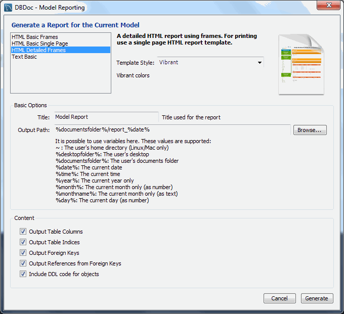
You can choose from four available templates:
HTML Basic Frames: Model documentation in HTML format that makes use of framesHTML Basic Single Page: Single Page HTML documentation, not using framesHTML Detailed Frames: Detailed HTML documentation, using framesText Basic: Text file documentation
When you click a template, a preview image displays on the right
side of the page. For the HTML Basic Frames
template, you can select either the Colorful or
the Restrained Colors option from the
Style list. The HTML Basic Single
Page template offers only the Colorful
style. The HTML Detailed Frames template offers
the Vibrant style, and also the more subdued
Coated style. The Text Basic
template offers only the Fixed Size Font style.
From the Base Options frame choose the report title and the output directory for the report files.
The following variables may be used to configure the output path:
~: The user's home directory. Available on Linux and OS X versions only.
%desktopfolder%: The user's desktop.
%documentsfolder%: The user's Documents folders. The following table shows typical values for common platforms:
Platform Typical Default Documents Folder Windows C:\Documents and Settings\user_name\My DocumentsLinux ~/DocumentsOS X Users/user_name/Documents%date%: The date in the format YYYY-MM-DD.
%time%: The time in the format HHMM.
%year%: The year in the format YYYY.
%month%: The month in the format MM. January is 01 and December is 12.
%monthname%: The name of the month, rather than the number.
%day%: The day number in the format DD. For example, the 12th would be 12.
Content options can also be set:
Render Table Columns: Display all the columns.Render Table Indices: Display all the indexes.Render Foreign Keys: Display all the foreign keys.List Foreign Keys that refer to that table: Display the tables that foreign keys reference.Include DDL code for objects: Generates DDL code.
Clicking the button creates the
directory defined in the Output directory text
box. If you chose to create HTML Basic Frames,
you will find the following files in this directory:
basic.css: The style sheet for theoverview.htmlpage.index.html: The main page.overview.html: The model overview, the navigation links shown in the sidebar.restrained.css: The CSS file used if theRestrained Colorsstyle option was chosen.table_details.html: The main frame of the model report.
Choosing the HTML Basic Single Page option
creates a style sheet and an index.html file.
Choosing the HTML Detailed Frames option creates
the following files:
basic.css: The style sheet for theoverview.htmlpage. This is used if thevibrantstyle is chosen.coated.css: The CSS file used if theCoatedstyle option was chosen.index.html: The main page.overview.html: Overview information for the report such as report title, project name and author.overview_list.html: A summary of schema in the model along with a list of tables contained in each schema.routine_details.html: List of all routines for the schema.table_details.html: The main report details.table_details_list.html: A Schema overview along with details of columns, indexes and foreign keys for each schema.table_element_details.html: The details for every element of the table.top.html: The top frame of the report.view_details.html: List of all columns and indexes for the schema.
Choosing the Text Basic option creates a
directory containing one text file.
You can click index.html to view a report. The
following screenshot shows the HTML Detailed
Frames report being displayed:
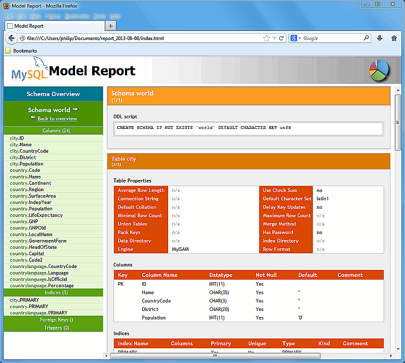
If you wish to create custom templates please refer to Section 9.7, “Customizing DBDoc Model Reporting Templates”.
MySQL Workbench provides validation modules so that you can test your models before implementing them.
This functionality is only available in the MySQL Workbench Commercial version.
The validation plugins are accessed from the menu. One plugin performs general validation for any Relational Database Management System (RDMS) and the other is MySQL specific. Beneath these menu items are a number of specific validation tests. Running any one of these tests opens an output window docked at the bottom of the application. Warning messages are displayed on the left side of this window and the tests performed are displayed on the right.
The following sections outline the tasks performed by the validation modules.
The following list names the general validation types and gives examples of specific violations:
Empty Content Validation
A table with no columns
A routine or view with no SQL code defined
A routine group containing no routines
A table, view, or routine not referenced by at least one role
A user with no privileges
Objects such as tables that do not appear on at least one EER Diagram
Table Efficiency Validation
A table with no primary key
A primary key that does not use an integer-based data type
A foreign key that refers to a column with a different data type
Duplicated Identifiers Validation
Duplicate object names
Duplicate role or user names
Duplicate index or routine names
Consistency Validation
Use of the same column with columns of differing data types
Logic Validation
A foreign key that refers to a column other than the primary key in the source table
Any object that is object is either read only or write only by role definition
Placeholder objects left over from reverse engineering
The following list names the MySQL-specific validation types and gives examples of specific violations:
Integrity Violation
An object name longer than the maximum permitted
A foreign key defined for an engine type that does not support foreign keys (not yet implemented)
A view or routine that references a nonexistent table (not yet implemented)
A default value that does not match a column's data type
An invalid partitioning scheme
Syntax Violation
A routine, trigger, or view with incorrect SQL syntax
A reserved keyword used as an identifier
Use of an invalid character
This chapter contains three short tutorials intended to familiarize you with the basics of MySQL Workbench. These tutorials show how MySQL Workbench can be used both to design and to document databases.
Creating a database from scratch is the focus of Section 9.3.4, “Using the Default Schema” and exploring the graphic design capabilities of MySQL Workbench is touched upon in Section 9.3.2, “Basic Modeling”. Both these tutorials show the database design capabilities of MySQL Workbench.
Importing an SQL data definition script is probably the quickest way
to familiarize yourself with MySQL Workbench—this tutorial makes
use of the sakila database and emphasizes the use
of MySQL Workbench as a documentation tool. Examples taken from the
sakila database are used throughout the
documentation, so this installation procedure is recommended.
This section provides a tutorial introduction to MySQL models by showing you how to create a new database model, and how to forward engineer a model to a live MySQL server.
Alternatively, you can create a model from a database by using the reverse engineering wizard. For additional information, see Section 9.4.2.2, “Reverse Engineering a Live Database”.
Start MySQL Workbench. On the Home window, click the [+] icon next to the Models section on the bottom of the page, or select , . A model can contain multiple schemata. Note that when you create a new model, it contains the
mydbschema by default. You can change the name of this schema to serve your own purposes, or delete it.Click the button on the right side of the Physical Schemata toolbar to add a new schema. The default schema name is "new_schema1", now change it to “dvd_collection” by modifying its Name field. Confirm this change in the Physical Schemata panel. Now you are ready to add a table.
Double-click Add Table in the Physical Schemata section.
This automatically loads the table editor with the default table name table1. Edit its Table Name field and change the table name from “table1” to “movies”.
Next, add columns to your table. Double-click a Column Name cell, and the first field defaults to “moviesid” because (by default) MySQL Workbench appends “id” to the table name for the initial field. Change “moviesid” to “movie_id” and keep the Datatype as
INT, and also select the PK (PRIMARY KEY), NN (NOT NULL), and AI (AUTO_INCREMENT) check boxes.Add two additional columns using the same method as described above:
Column Name Data Type Column Properties movie_title VARCHAR(45) NN release_date DATE (YYYY-MM-DD) None For a visual representation (EER diagram) of this schema, select , to create the EER Diagram for the model.
In the table editor, change the name of the column “movie_title” to “title”. Note that the EER Diagram is automatically updated to reflect this change.
NoteTo open the table editor, either change back to the MySQL Model tab and right-click on the
moviestable, or right-click onmoviesin the EER diagram and select an option.Save the model by choosing , from the main menu, or click on the toolbar. Enter a model name at the file prompt. For this tutorial, enter “Home_Media” and then the model.
Before synchronizing your new model with the live MySQL server, confirm that you already created a MySQL connection. This tutorial assumes you followed the previous Section 5.2, “Creating A New MySQL Connection (Tutorial)” tutorial to create a MySQL connection named MyFirstConnection, although an alternative connection can also work.
Now forward engineer your model to the live MySQL server. Select , from the main menu to open the Forward Engineer to Database wizard.
The Connection Options page selects the MySQL connection and optionally sets additional options for the selected MySQL connection. We do not require connection changes so click .
NoteYou may decided to choose a different MySQL connection here, but this tutorial uses MyFirstConnection.
The Options page lists optional advanced options. For this tutorial, you can ignore these and click Next.
Select an object to export to the live MySQL server. In this case, we only have one table (dvd_collection), so select
dvd_collectionand click .The Review SQL Script page displays the SQL script that will be executed on the live server to create your schema. Review the script to make sure that you understand the operations that will be carried out.
Click to execute the Forward Engineering process.
The Commit Progress page confirms that each step was executed. Click to view the logs. If no errors are present, click to close the wizard.
The new
dvd_collectiondatabase is now present on the MySQL server. Confirm this by opening the MySQL connection and viewing the schema list, or by executingSHOW DATABASESfrom the MySQL Command Line Client (mysql).Ensure that your model is saved. Click Save Model to Current File on the main toolbar.
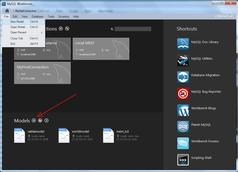
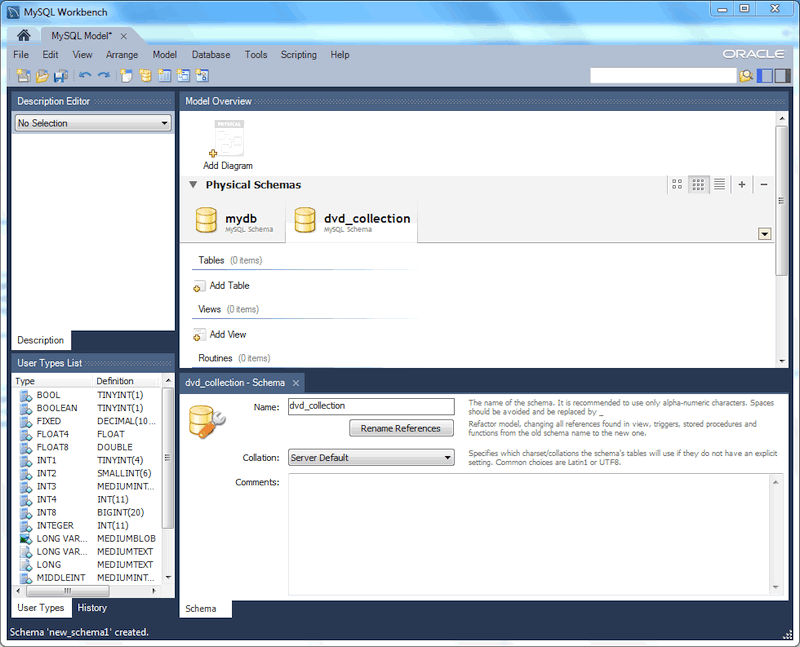
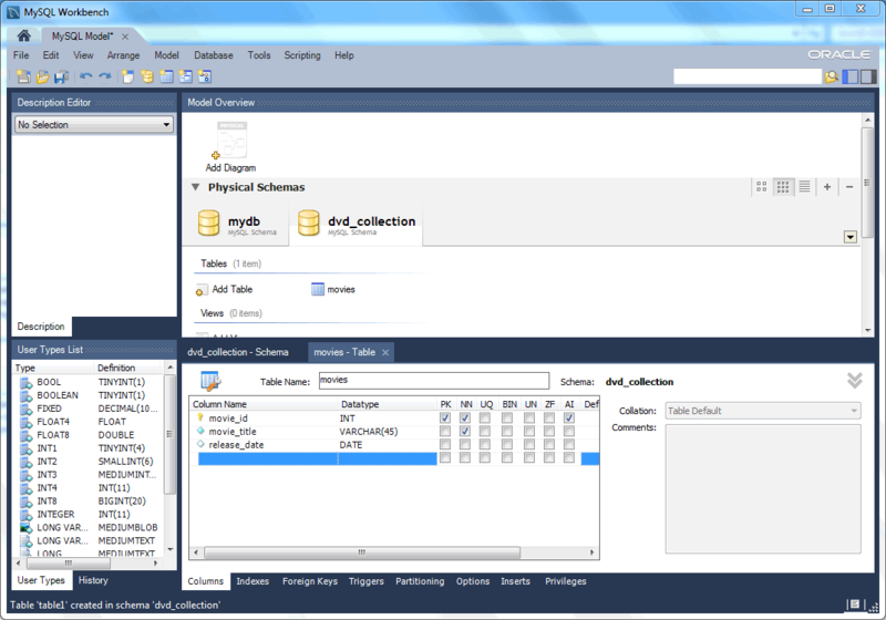
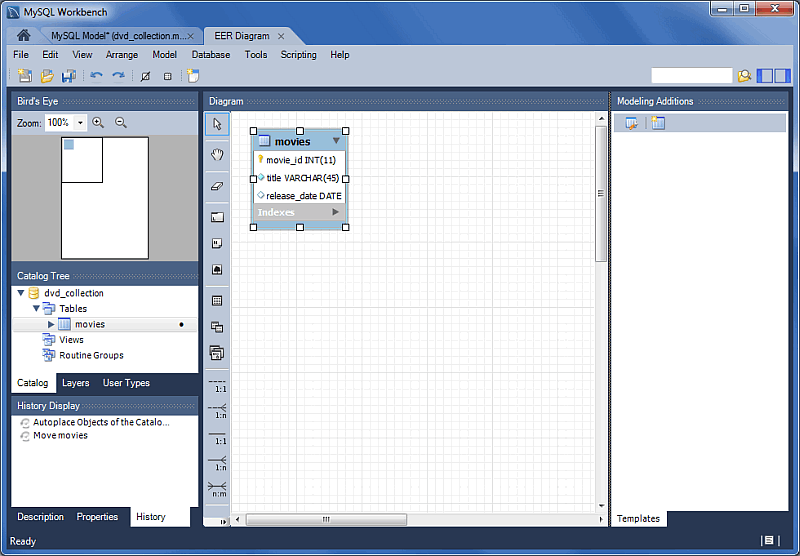
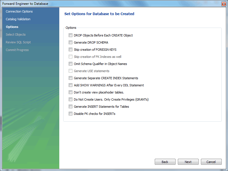
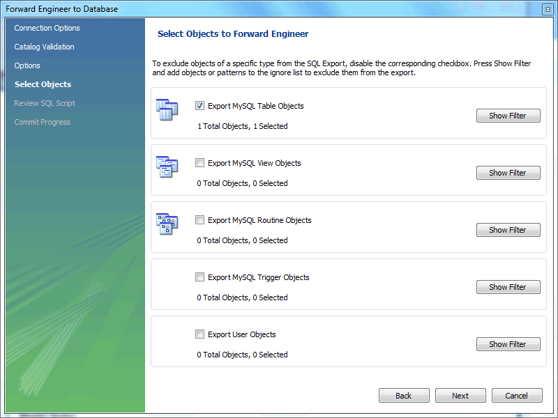
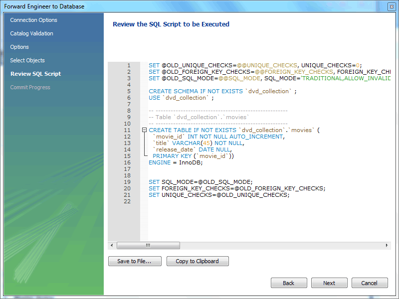
For additional information about data modeling, see Chapter 9, Database Design / Modeling.
On the MySQL Model page, double-click the
Add
    Diagram
icon. This creates and opens a
new EER Diagram canvas.
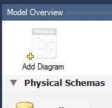
From an EER diagram page you can graphically design a database.
The tools in the vertical toolbar on the left of the
EER Diagram tab are used for designing an
EER diagram. Start by creating a table using the table tool. The
table tool is the rectangular grid in the middle of the vertical
toolbar. Mousing over it shows the message, Place a New
Table (T).
Clicking this tool changes the mouse pointer to a hand with a
rectangular grid. Create a table on the canvas by clicking
anywhere on the EER Diagram grid.
Right-click the table and choose from the pop-up menu. This opens the table editor, docked at the bottom of the application.
The table name defaults to table1. Change the
name by entering invoice into the
Name: field. Changes here affect the name
of the tab in the table editor and the name of the table on the
canvas.
Pressing Tab or Enter while
the cursor is in the table name field selects the
Columns tab of the table editor and creates
a default column named idinvoice.
Pressing Tab or Enter again
sets the focus on the Datatype list with
INT selected. Notice that a field has been
added to the table on the EER canvas.
Pressing Tab yet again and the focus shifts to
adding a second column. Add a Description and
a Customer_id column. When you are finished,
close the table editor, by clicking the
button on the top left of the table editor.
Select the table tool again and place another table on the
canvas. Name this table invoice_item. Next
click the 1:n Non-Identifying Relationship
tool.
First, click the invoice_item table; notice
that a red border indicates that this table is selected. Next,
click the invoice table. This creates a
foreign key in the invoice_item table, the
table on the “many” side of the relationship. This
relationship between the two tables is shown graphically in
crow's foot notation.
Revert to the default mouse pointer by clicking the arrow at the
top of the vertical toolbar. Click on the
invoice_item table and select the
Foreign keys tab.
Click the Foreign key Name field. The referenced table should show in the Referenced Table column and the appropriate column in the Referenced Column column.
To delete the relationship between two tables, click the line joining the tables and then press Control+Delete.
Experiment with the other tools on the vertical toolbar. Delete a relationship by selecting the eraser tool and clicking the line joining two tables. Create a view, add a text object, or add a layer.
Save your changes to a MySQL Workbench Models
file (mwb extension) by choosing
from the
menu or by using the keyboard command
Control+S.
For this tutorial, use the sakila database
script, which you can find by visiting the
http://dev.mysql.com/doc/ page, selecting the Other
Docs tab, and looking in the Example
Databases section
After downloading the file, extract it to a convenient location.
Open MySQL Workbench and find the menu item by first choosing
and then .
Find and import the sakila-schema.sql file.
This is the script that contains the data definition statements
for the sakila database. The file filter for
the file open dialog window defaults to *.sql
so you should be able to view only files with the
sql extension.
If the file was successfully imported, the application's status
bar reads, Import MySQL Create Script done. To
view the newly imported script, expand the Physical
Schemata section by double-clicking the arrow on the
left of the Physical Schemata title bar. Select
the tab labeled sakila.
You may also wish to remove the default schema tab,
mydb. Select this tab, then click the
button on the upper right in the
Physical Schemata panel.
To view all the objects in the sakila schema,
you may need to expand the Physical Schemata
window. Move the mouse pointer anywhere over the gray area that
defines the lower edge of the Physical
Schemata window. Hold down the right mouse button and
move the mouse to adjust the size of the window.
After you have expanded the window, all the objects in the
sakila database should be visible. Tables
appear at the top followed by views and then routines. There are
no routine groups in this schema, but you should see the
Routine Groups section and an Add
Group icon.
For a complete description of importing a MySQL create script, see Section 9.4.2.1, “Reverse Engineering Using a Create Script”.
To create an EER diagram for the sakila
database, first add an EER diagram by double-clicking the
Add Diagram icon in the EER
Diagrams panel to create and open a new EER
Diagram editor.
The EER Diagram canvas is where object
modeling takes place. To add a table to the canvas, select the
Catalog tab in the middle panel on the
right side of the application to display any schemata that
appear in the MySQL Model tab. Find the
sakila schema and expand the view of its
objects by clicking the button to the
left of the schema name. Expand the tables list in the same way.
You can add tables to the EER canvas by dragging them from the
Catalog panel dropping them onto the
canvas. Drop the address table and the
city table onto the canvas.
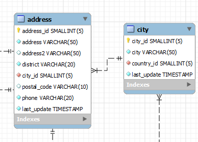
MySQL Workbench automatically discovers that
address.city_id has been defined as a foreign
key referencing the city.city_id field. Drop
the country table onto the canvas and
immediately you should see the relationship between the
country table and the city
table. (To view all the relationships in the
sakila database, see
Figure 9.29, “The sakila Database EER Diagram”.)
Click the Properties tab of the panel on
the lower left, then click one of the tables on the canvas. This
displays the properties of the table in the
Properties window. While a table is selected,
you can use the Properties window to change a
table's properties. For example, entering
#FF0000 for the color value will change the
color accent to red.
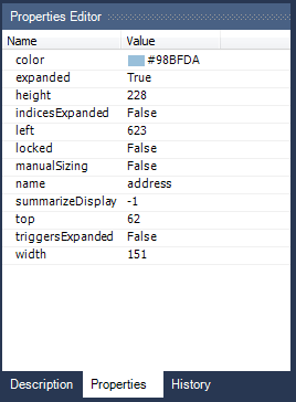
Changing the color of a table is a good way to identify a table
quickly—something that becomes more important as the
number of tables increases. Changing the color of a table is
also an easy way to identify a table in the Model
Navigator panel. This panel, the uppermost panel on
the left side of the page, gives a bird's eye view of the entire
EER canvas.
Save your changes to a MySQL Workbench Models
file (mwb extension) by choosing
from the
menu or by using the keyboard command Control +
S.
When you first open MySQL Workbench a default schema,
mydb appears as the leftmost tab of the
Physical Schemata section of MySQL Workbench. You
can begin designing a database by using this default schema.
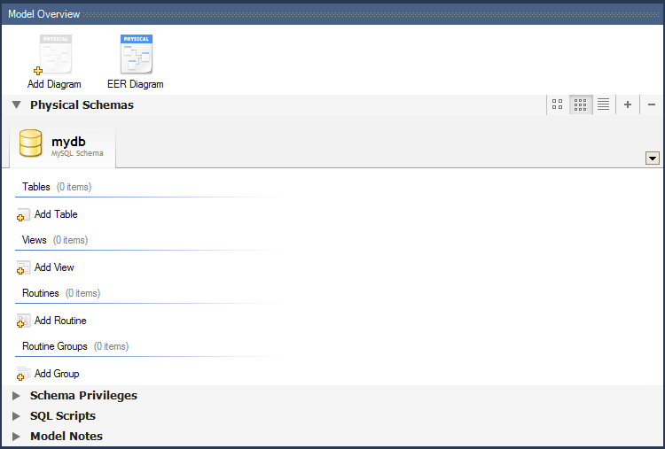
To change the name of the default schema, double-click the schema tab. This opens a schema editor window docked at the bottom of the application. To undock or redock this window, double-click anywhere in the editor title bar.
To rename the schema, use the field labeled Name. After you have renamed the schema, a lightning bolt icon appears right aligned in the Name field, indicating that other changes are pending. Click the Comments field and a dialog box opens asking if you wish to rename all schema occurrences. Clicking ensures that your changes are propagated throughout the application. Add comments to the database and change the collation if you wish. Close the schema editor by clicking the button.
Create a new table by double-clicking the Add
Table icon in the Physical
Schemata panel. This opens the table editor docked at
the bottom of the application. If you wish, you can undock or
dock this editor in exactly the same way as the schema editor
window.

Initially, the table name defaults to 'table1' in the table editor. The following screenshot describes the available actions:
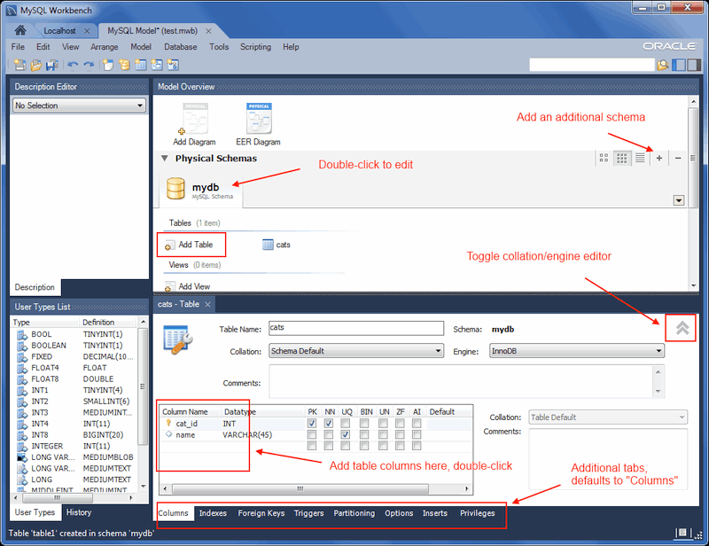
In our example above, columns were added using the Columns tab. Clicking an empty row will add a new column, and clicking an existing column starts edit mode. Click the Tab key to move to the next column and set the column's data type.
Altering the table by adding indexes or other features is also possible using the table editor by clicking each tab within the table editor.
Additional objects such as views or routines can be added in the same way as tables.
Objects are listed under the Catalog palette on the right. To view these schema objects, select the Catalog tab in the middle palette on the right. View all the objects by clicking the button to the left of the schema name.
Save your changes to a MySQL Workbench Models
file (mwb extension) by choosing
from the
menu or by using the keyboard command
Control+S.
This chapter highlights the capabilities of MySQL Workbench as a
documentation tool using the sakila database as
an example. This is a sample database provided by MySQL that you can
find by visiting the http://dev.mysql.com/doc/ page, selecting
the Other Docs tab, and looking in the
Example Databases section
An EER diagram provides a quick overview and understanding of a database. Rather than reading through table definition statements, a quick glance at an EER diagram indicates how tables are related.
You can also see how tables are related; what the foreign keys are and what the nature of the relationship is.
Find following an EER diagram showing all the tables in the
sakila database. This image was created using
the , ,
menu item.

The object notation style used in
Figure 9.29, “The sakila Database EER Diagram” is Workbench (PKs
only). This notation shows only primary keys and no
other columns, which is especially useful where space is at a
premium. The relationship notation is the default, Crow's Foot.
As the connection lines show, each table is related to at least
one other table in the database (with the exception of the
film_text table). Some tables have two foreign
keys that relate to the same table. For example the
film table has two foreign keys that relate to
the language table, namely
fk_film_language_original and
fk_film_language. Where more than one
relationship exists between two tables, the connection lines run
concurrently.
Identifying and nonidentifying relationships are indicated by
solid and broken lines respectively. For example, the foreign key
category_id is part of the primary key in the
film_category table so its relationship to the
category table is drawn with a solid line. On
the other hand, in the city table, the foreign
key, country_id, is not part of the primary key
so the connection uses a broken line.
MySQL Workbench provides capabilities to forward engineering physical database designs. A visual data model can be transformed into a physical database on a target MySQL Server by executing the forward engineering wizard. All SQL code is automatically generated to help eliminate the normal error-prone process of manually writing complex SQL code. MySQL Workbench also enables you to reverse engineer an existing database or packaged application to get better insight into its database design. In addition to forward and reverse engineering existing databases, it can also import SQL scripts to build models, and export models to DDL scripts to execute at a later time.
It is possible to forward engineer a database using an SQL script or by connecting to a live database.
To create a script of your database model, choose the
item from the
menu. You may export a script to alter an
existing database or create a new database. The script to create a
database is similar to the one created using the
mysqldump db_name
command.
Choosing to create a database yields additional options.
Select the , , menu item to start the Forward Engineer SQL Script wizard. The following figure shows the first page of the wizard.
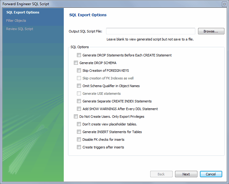
The SQL Export Options displays the following facilities:
Output SQL Script FileTo specify the output file name, enter it into the Output SQL Script File field, or use the button to select a file. Leave this field blank to view, but not save, the generated output.
Generate DROP Statements Before Each CREATE StatementSelect this option to generate a statement to drop each object before the statement that creates it. This ensures that any existing instance of each object is removed when the output is executed.
Generate DROP SCHEMASkip creation of FOREIGN KEYSSkip creation of FK Indexes as wellOmit Schema Qualifier in Object NamesSelect this option to generate unqualified object names in SQL statements.
Generate USE statementsGenerate Separate CREATE INDEX StatementsSelect this option to create separate statements for index creation instead of including index definitions in
CREATE TABLEstatements.Add SHOW WARNINGS after every DDL statementSelect this option to add
SHOW WARNINGSstatements to the output. This causes display of any warnings generated when the output is executed, which can be useful for debugging.Do Not Create Users. Only Export PrivilegesSelect this option to update the privileges of existing users, as opposed to creating new users. Exporting privileges for nonexistent users will result in errors when you execute the
CREATEscript. Exporting users that already exist will also result in an error.Don't create view placeholder tablesGenerate INSERT Statements for TablesSelect this option if you have added any rows to a table. For more information about inserting rows, see Section 8.1.1, “SQL Query Window”.
Disable FK checks for insertsCreate triggers after inserts
Clicking takes you to the SQL Object Export Filter page where you select the objects you wish to export.
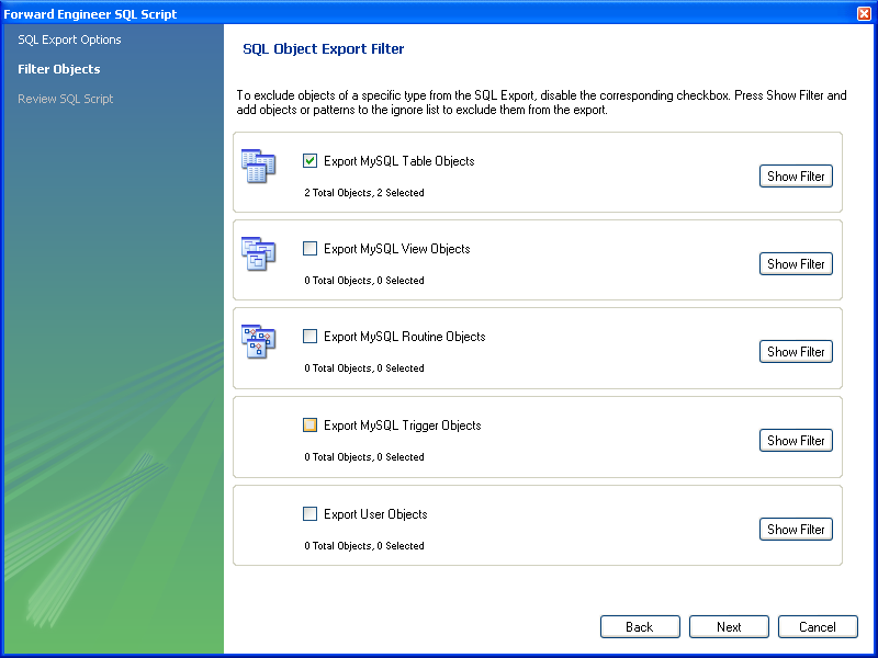
Use to fine tune (filter) the objects for export. After selecting the objects to export, click to hide the filter panel.
After selecting the objects to export, click to review the generated script.
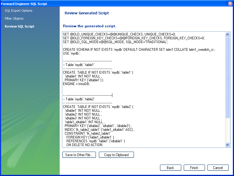
You may return to the previous page using the button.
The button saves the script file and exits. You can then use the saved script to create a database.
The menu item for creating an ALTER Script File is , . Typically, this option is used when the SQL script of a database has been imported into MySQL Workbench and changed, and then you want to create a script that can be executed against the database to alter it to reflect the adjusted model. For instructions on importing a DDL script, see Section 9.4.2.1, “Reverse Engineering Using a Create Script”.
Select the , menu item to start the wizard. You will be presented with the first page showing the introduction, and then the available options:
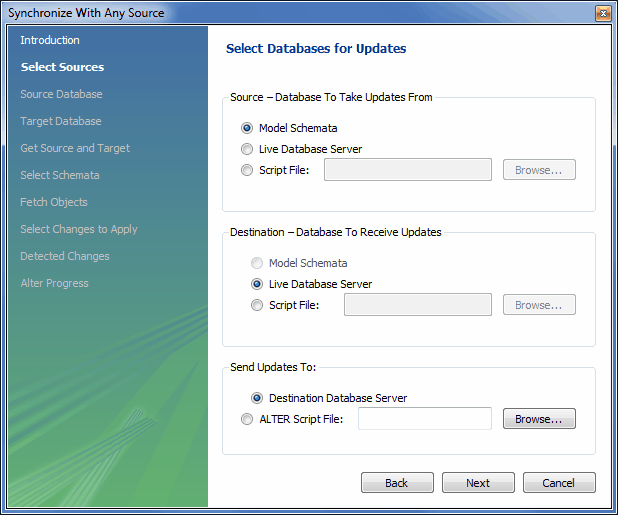
For additional information, see Section 9.5.1, “Database Synchronization”.
Use forward engineering to export your schema design to a MySQL server.
Select the model that you wish to forward engineer and then choose the , menu item from the main menu.
The first step of the process is to connect to a MySQL server to create the new database schema. This page enables you to use a previously stored connection, or enter the connection parameters.
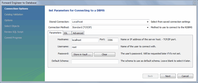
Click after setting the connection parameters. The next page of the wizard displays is Catalog Validation (validation is available only in the Commercial Edition).
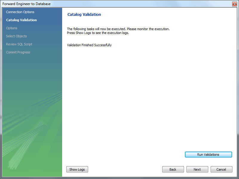
Click to validate the catalog.
Click to continue.
The next page enables you to set options for the database to be created. These options are as described in Section 9.4.1.1.1, “Creating a Schema”.
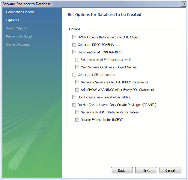
Select the required options and then click .
The next page enables you to select the objects to forward engineer.
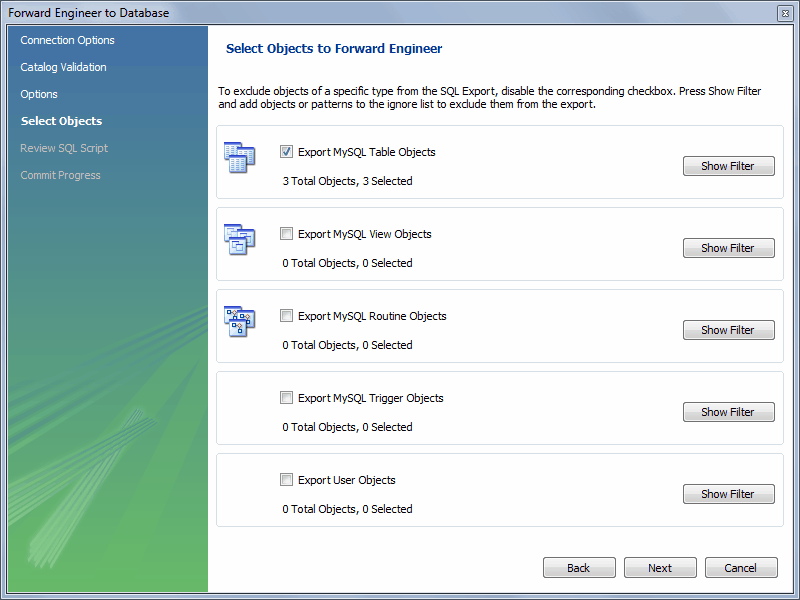
To select a subset of objects to forward engineer, use the / button, then select specific objects. After you have selected your objects, click to continue
On the Review Script page you may review and edit the SQL script that will be executed.

Click to continue if you are satisfied with the generated script.
The next page of the wizard displays the results of the forward engineering process.
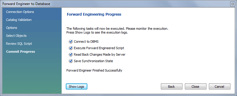
You can confirm that the script created the schema by connecting
to the target MySQL server and issuing a SHOW
DATABASES statement.
With MySQL Workbench, you can reverse engineer a database using a MySQL create script or you can connect to a live MySQL server and import a single database or a number of databases. All versions of MySQL Workbench can reverse engineer using a MySQL DDL script. Only commercial versions of MySQL Workbench can reverse engineer a database directly from a MySQL server.
To reverse engineer using a create script, choose the , , menu item for a model.
Tables, views, routines, routine groups, indexes, keys, and constraints can be imported from an SQL script file. Objects imported using an SQL script can be manipulated within MySQL Workbench the same as other objects.
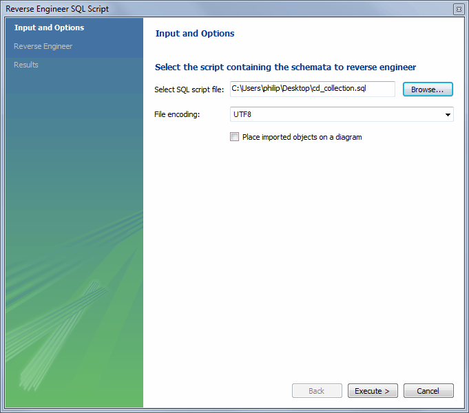
Select SQL script file: Open a file open dialog box with the default file type set to an SQL script file, a file with the extension
sql.File encoding: Defaults to UTF8.
Place imported objects on a diagram: Also create an EER diagram in MySQL Workbench.
NoteImporting a large number (about 300+) objects could fail to create an EER diagram and instead emit a resource warning with the text "Too many objects are selected for auto placement. Select fewer elements to create the EER diagram." In this case, execute the reverse engineering wizard with this option disabled, manually create the EER diagram, and then import the 300+ objects using the EER diagram catalog viewer.
If your script creates a database, MySQL Workbench creates a new
physical schemata tab on the MySQL Model page.
Click to reverse engineer the SQL script, verify its results, and optionally place the objects in a new EER diagram.
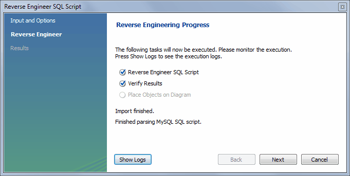
Click to view a summary of the results, and then to close the wizard.
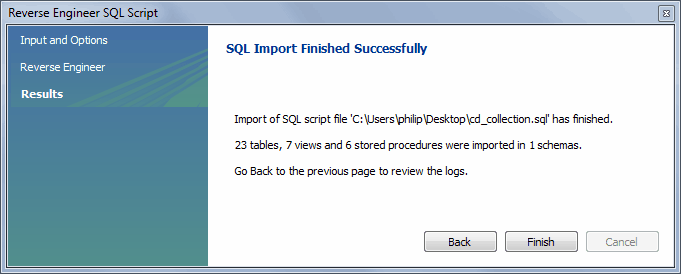
Before exiting MySQL Workbench, be sure to save the schema. Choose the
, menu item
and the reverse-engineered database will be saved as a MySQL
Workbench file with the extension mwb.
See Section 9.3.3, “Importing a Data Definition SQL Script”, for a tutorial on
reverse engineering the sakila database.
Creating a DDL script
You can create a data definition (DDL) script by executing the
mysqldump command.
Using the db_name
--no-data >
script_file.sql--no-data option ensures that the
script contains only DDL statements. However, if you are working
with a script that also contains DML statements you need not
remove them; they will be ignored.
If you plan to redesign a database within MySQL Workbench and then
export the changes, be sure to retain a copy of the original DDL
script. You will need the original script to create an
ALTER script. For more information, see
Section 9.4.1.1.2, “Altering a Schema”.
Use the --databases option with
mysqldump if you wish to create the database as
well as all its objects. If there is no CREATE DATABASE
statement in your
script file, you must import the database objects into an existing
schema or, if there is no schema, a new unnamed schema is created.
db_name
To reverse engineer a live database, choose the , menu item from the main menu. This opens the Reverse Engineer Database wizard.
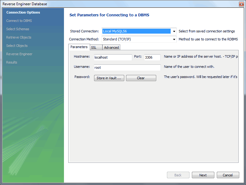
The first page of the wizard enables you to set up a connection to the live database you wish to reverse engineer. You can set up a new connection or select a previously created stored connection. Typical information required for the connection includes host name, user name and password.
After this information has been entered, or you have selected a stored connection, click the button to proceed to the next page.
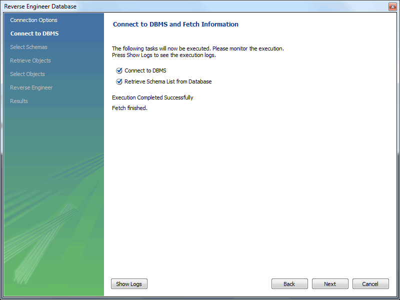
Review the displayed information to make sure that the connection did not generate errors, then click .
The next page displays the schemata available on the server. Click the check box or check boxes for any schemata you wish to process.
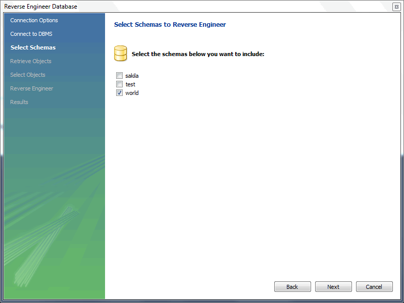
After you have selected the desired schemas, click the button to continue.
The wizard then displays the tasks it carried out and summarizes the results of the operation.
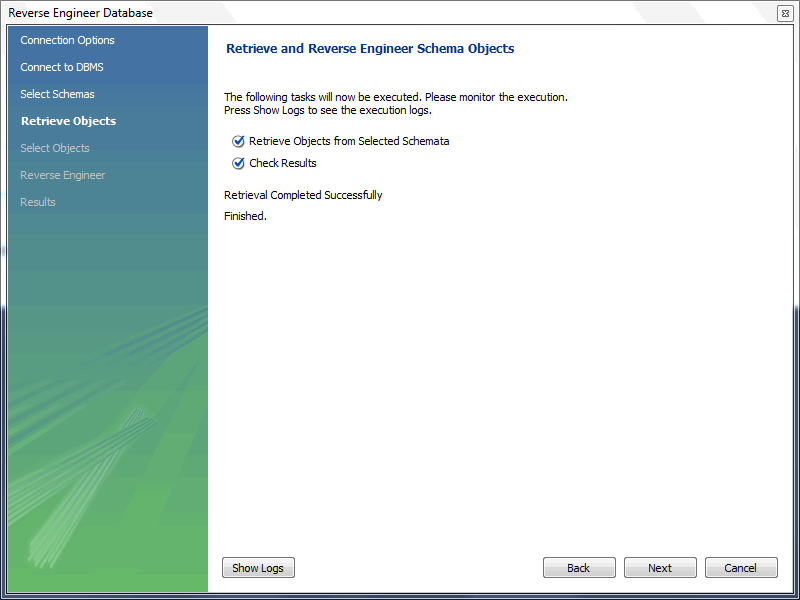
Review the results before clicking to continue.
The next page is the Select Objects page. It
has a section for each object type present in the schema (tables,
views, routines, and so forth). This page is of special interest
if you do not wish to import all the objects from the existing
database. It gives you the option of filtering which objects are
imported. Each section has a
button. Click this button if you do not want to import all the
objects of a specific type. Here is this page with the filter
open:
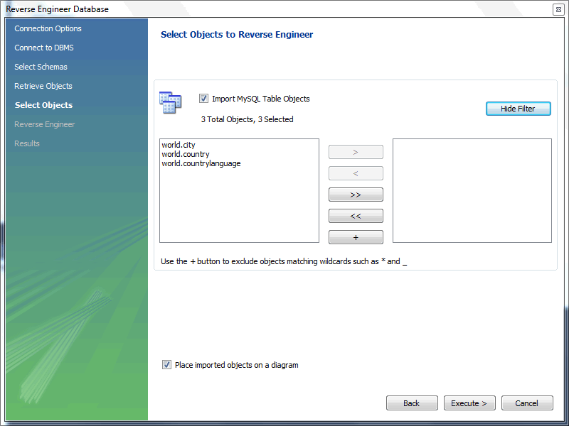
This page enables you to select specific tables for import. Having selected the desired tables, you can optionally hide the filter by clicking the button.
The other sections, such as MySQL Routine Objects, have similar filters available.
Click to continue to the next page.
The wizard then imports objects, displaying the tasks that have been carried out and whether the operation was successful. If errors were generated, you can click the button to see the nature of the errors.
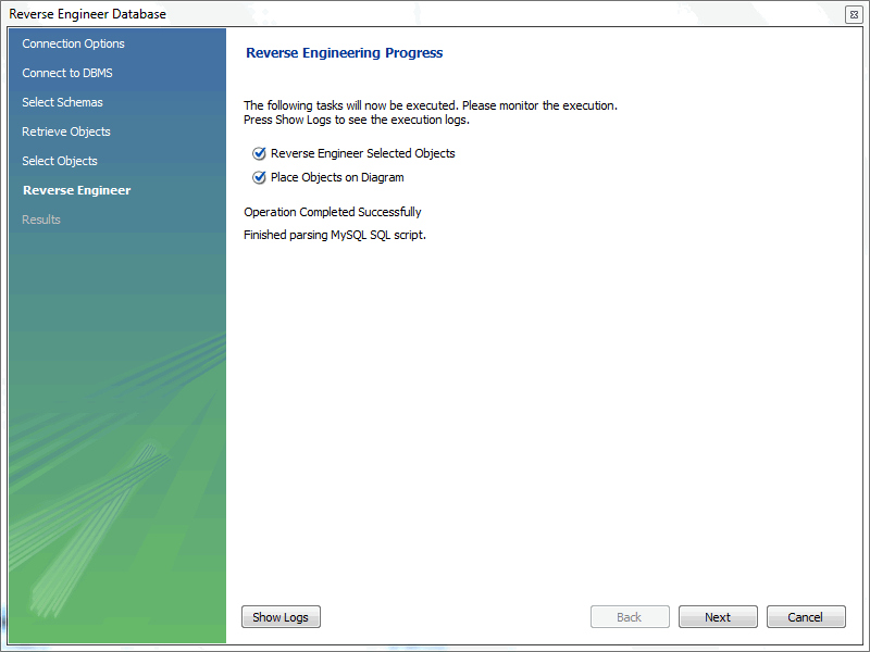
Click to continue to the next page.
The final page of the wizard provides a summary of the reverse engineered objects.
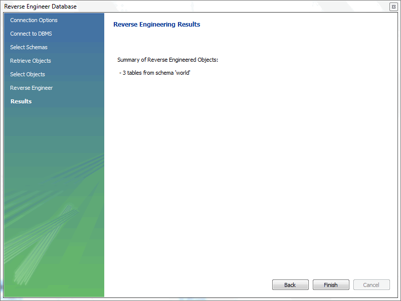
Click to exit the wizard.
Before exiting MySQL Workbench be sure to save the schema. Choose the
, menu item
to save the reverse-engineered database as a MySQL Workbench file with
the extension mwb.
During reverse engineering, the application checks for tables and views that duplicate existing names and disallows duplicate names if necessary. If you attempt to import an object that duplicates the name of an existing object you will be notified with an error message. To see any errors that have occurred during reverse engineering, you can click the button . This will create a panel containing a list of messages, including any error messages than may have been generated. Click the button to close the panel.
If you wish to import an object with the same name as an existing object, rename the existing object before reverse engineering.
If you import objects from more than one schema, there will be a
tab in the Physical Schemata section of the
MySQL
      Model
page for each schema imported.
You cannot reverse engineer a live database that has the same name as an existing schema. If you wish to do this, first rename the existing schema.
Database change management is a complex process that involves maintaining different versions of database schemas and manually modifying existing databases. To help with this administration task, MySQL Workbench includes schema synchronization and comparison utilities. You can compare two live databases, two models, or models with live databases, to visually see the differences and optionally perform a synchronization routine.
Synchronize data between models, databases, and SQL files. These three types can be the target (destination), source, or both. You can also select/deselect individual objects and modify their direction during the synchronization. For example, synchronize tables from a model to your database, other tables from your database to your model, and skip a few tables, all during the same synchronization process.
Be aware that backward incompatible MySQL syntax changes are introduced over time, so for this reason it is important to set the Default Target MySQL Version modeling preference according to your needs. For example, exporting results from a MySQL 5.7 target might yield invalid syntax when executed against MySQL 5.1. See also Section 3.2.4, “Modeling Preferences”.
To start, select from the navigation menu. Alternatively, select Synchronize Model to open the same wizard that defaults to a model. A Model or EER diagram must be selected for these synchronization options to be present under the navigation menu.
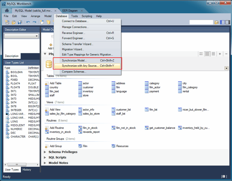
Because MySQL databases correspond to directories within the data
directory, you must consider case sensitivity for database, table,
and trigger names, which follow the case sensitivity rules of the
underlying file system for your operating system. Synchronizing
models with objects that differ in case may lead to MySQL Workbench
producing a DROP statement for that object,
before recreating it as lowercase. For more information, see
Identifier Case Sensitivity
Workarounds include using a consistent convention, where the most
portable code uses lower case database and table names. Or a
temporary workaround is to delete the DROP SCHEMA IF
EXISTS line from the generated query.
MySQL Workbench enables control over objects to synchronize, and the direction of synchronization for each object. Synchronization options include:
Specify all or specific tables and objects to synchronize
Synchronize both the model and live database, or only update one or the other (unidirectional or bidirectional)
Optionally update from or to an SQL script file
Instead of executing the synchronization, you may generate an ALTER Script File to later perform the appropriate updates
Fine-tune how the synchronization will be performed by choosing the direction of each individual object, or configuring particular objects to be ignored
There are two similar database synchronization wizards available from the menu. The simpler Synchronize Model wizard, and the more flexible Synchronize with Any Source wizard. The descriptions below apply to both, unless explicitly told otherwise.
Synchronize Model (with database)
To start the wizard, open a model and select , from the main menu. Follow the steps until you reach the Select Changes to Apply step:
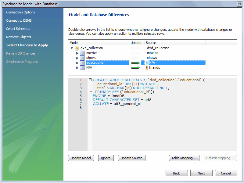
In the preceding example, the live database and model both have
movies shows tables. In the
MySQL Workbench, an additional table, educational,
has been created in the model, but it lacks an equivalent in the
live database. Further, friends exists in the
live database, but it is not in the model. By default, the actions
will synchronize the database with the model, so in this example the
educational table will be added to the source,
and the friends table will be removed from the
source.
As described in the GUI, double-clicking the arrows will alternate between the , , and actions. You may also select a row and click one of the three action buttons. Also note that clicking on a row will reveal the associated SQL statement, as shown in the screenshot above.
The next example shows how the direction of synchronization can be changed.
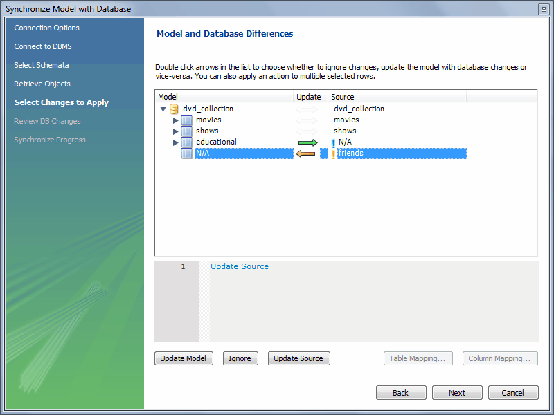
In this case, the synchronization direction has been changed so that
rather than the default action of friends being
dropped from the live database, it will be incorporated into the
MySQL Workbench model. As before, educational table
will be added to the live (source) database.
The three actions available actions are:
: Causes the selected changes to be applied to the model, from the live database.
: Causes the changes to be ignored. No synchronization will take place for those changes. This is designated with a double arrow that is crossed out.
: Causes the changes to be applied only to the live database.
Clicking offers additional mapping options:
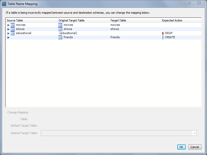
Pressing will reveal the SQL statement to perform the configured model and live database (source) synchronization:
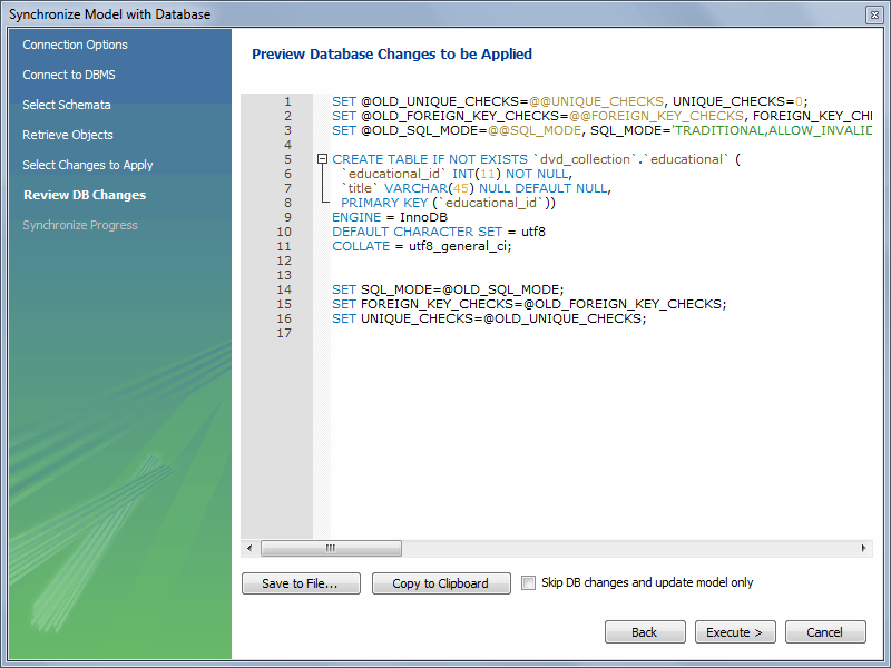
You may now save the SQL statement to a file or the clipboard, or execute the SQL statement. If you choose to execute the change in MySQL Workbench, then you may optionally choose to skip "DB changes" so that only your model is altered.
Synchronize With Any Source
To start the wizard, open a model and select , from the main menu. The steps are similar to the Synchronize Model wizard, but with additional options to create and/or use SQL script files. See the Select Sources page:
Notice how the source and destination types can be altered. The steps that follow depend on these source and destination types, and the Synchronize Model describes the basic functionality of this wizard.
This facility enables you to create a report detailing the differences between your MySQL Workbench model, and a live database or script. Choose , from the main menu to run the Compare and Report Differences in Catalogs wizard.
The first step in the wizard is to specify which catalogs to compare. For example, you may wish to compare your live database against your current MySQL Workbench model.
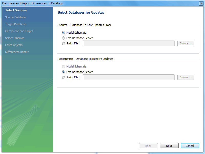
You then proceed through the wizard, providing connection information if accessing a live database. The wizard then produces a catalog diff report showing the differences between the compared catalogs.
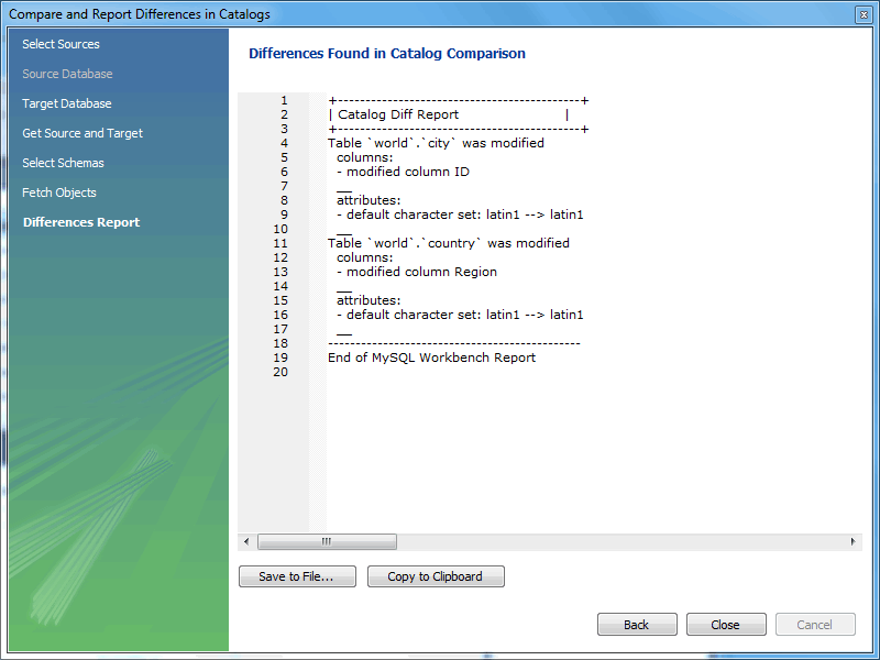
Define table templates with commonly used columns and settings to create new tables from either a live connection or while creating an EER model.
From the SQL editor, select from the Tables context menu.
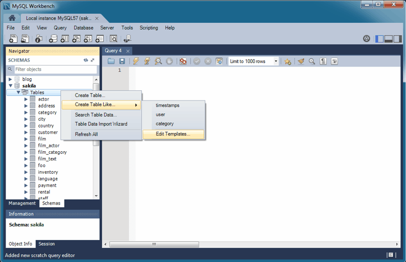
Or while modeling, click the "Open the table template editor" icon on the right sidebar under Modeling Additions.
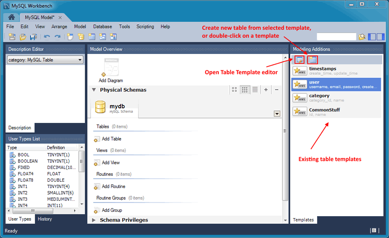
After opening the Table Templates manager, make the desired adjustments and click to commit the changes.
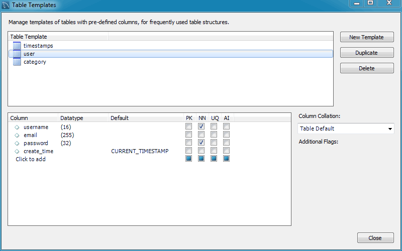
To open an existing template from the SQL editor, hover over the context menu and select the desired table template. For modeling, double-click on a template in the right modeling sidebar.
This section provides an overview of creating and modifying DBDoc Model Reporting templates, as used by MySQL Workbench.
The MySQL Workbench DBDoc Model Reporting system is based on the Google Template System. This discussion does not attempt to explain the Google Template System in detail. For a useful overview of how the Google Template System works, see the Google document, How To Use the Google Template System.
The templates employed by the DBDoc Model Reporting system are text files that contain Markers. These text files are processed by the template system built into MySQL Workbench, and the markers replaced by actual data. The output files are then generated. It is these output files, typically HTML or text, that are then viewed by the user.
Markers can be of six types:
Template Include
Comment
Set delimiter
Pragma
Variable
Section start and Section end
The last two are the most commonly used in MySQL Workbench templates and these important markers are briefly described in the following sections.
Variables
Variable usage in the templates is straightforward. Variables denoted by markers in the template file are replaced by their corresponding data prior to the generated output file. The mapping between variables and their corresponding data is stored by MySQL Workbench in a data dictionary. In the data dictionary, the variable name is the key and the variable's corresponding data is the value. MySQL Workbench builds the data dictionaries and fills it with the data contained in the processed model.
By way of example, the following code snippet shows part of a template file:
Total number of Schemata: {{SCHEMA_COUNT}}In the generated output file, the variable
{{SCHEMA_COUNT}}is replaced by the number of schemata in the model:Total number of Schemata: 2
A variable can appear multiple times in the template file.
Sections
Sections are used to perform iteration in the templates. When MySQL Workbench exchanges the variables in a section for data, it does so iteratively, using all data in the data dictionary in which the variable is defined. MySQL Workbench builds the data dictionaries according to the model currently being processed.
Consider the following code snippet:
{{#SCHEMATA}}
Schema: {{SCHEMA_NAME}}
{{/SCHEMATA}}
In the preceding snippet, the section start and end are indicated by the
{{#SCHEMATA}}and{{/SCHEMATA}}markers. When MySQL Workbench processes the template, it notes the section and iterates it until the variable data for{{SCHEMA_NAME}}in the corresponding data dictionary is exhausted. For example, if the model being processed contains two schemata, the output for the section might resemble the following:Schema: Airlines Schema: Airports
Data Dictionaries
It is important to understand the relationship between sections and data dictionaries in more detail. In a data dictionary the key for a variable is the variable name, a marker. The variable value is the variable's data. The entry for a section in a data dictionary is different. For a section entry in a data dictionary, the key is the section name, the marker. However, the value associated with the key is a list of data dictionaries. In MySQL Workbench each section is usually associated with a data dictionary. You can think of a section as activating its associated dictionary (or dictionaries).
When a template is processed, data dictionaries are loaded in a hierarchical pattern, forming a tree of data dictionaries. This is illustrated by the following table.
Table 9.1 Data Dictionaries Tree
| Data Dictionary | Loads Data Dictionary |
|---|---|
| MAIN | SCHEMATA |
| SCHEMATA | TABLES, COLUMNS (Detailed is true), FOREIGN_KEYS (Detailed is true), INDICES (Detailed is true) |
| TABLES | REL_LISTING, INDICES_LISTING, COLUMNS_LISTING, TABLE_COMMENT_LISTING, DDL_LISTING |
| COLUMNS_LISTING | COLUMNS (Detailed is false) |
| REL_LISTING | REL (Detailed is false) |
| INDICES_LISTING | INDICES (Detailed is false) |
The root of the tree is the main dictionary. Additional dictionaries are loaded from the root to form the dictionary tree.
If a template has no sections, any variables used in the template are looked up in the main dictionary. If a variable is not found in the main dictionary (which can be thought of as associated with the default, or main, section), no data is generated in the output file for that marker.
Evaluation of variables
The tree structure of the data dictionaries is important with respect to variable evaluation. As variables are defined in data dictionaries, their associated values have meaning only when that particular data dictionary is active, and that means when the section associated with that data dictionary is active. When a variable lookup occurs, the system checks the data dictionary associated with the current section. If the variable value can be found there, the replacement is made. However, if the variable's value is not found in the current data dictionary, the parent data dictionary is checked for the variable's value, and so on up the tree until the main data dictionary, or root, is reached.
Suppose that we want to display the names of all columns in a model. Consider the following template as an attempt to achieve this:
Report
------
Column Name: {{COLUMN_NAME}}
This template produces no output, even for a model that contains one
or more columns. In this example, the only data dictionary active is
the main dictionary. However, COLUMN_NAME is
stored in the COLUMNS data dictionary, which is
associated with the COLUMNS section.
With this knowledge, the template can be improved as follows:
Report
------
{{#COLUMNS}}
Column Name: {{COLUMN_NAME}}
{{/COLUMNS}}
This still does not produce output. To see why, see
Table 9.1, “Data Dictionaries Tree”. The
COLUMNS data dictionary has the parent dictionary
COLUMNS_LISTING.
COLUMNS_LISTING has the parent
TABLES, which has the parent
SCHEMATA, whose parent is the main dictionary.
Remember that for a dictionary to be involved in variable lookup,
its associated section must currently be active.
To achieve the desired output, the template must be something like the following:
Report
------

{{#SCHEMATA}}
{{#TABLES}}
{{#COLUMNS_LISTING}}
{{#COLUMNS}}
Column Name: {{COLUMN_NAME}}
{{/COLUMNS}}
{{/COLUMNS_LISTING}}
{{/TABLES}}
{{/SCHEMATA}}
The following template is the same, but with explanatory comments added:
Report
------

{{! Main dictionary active}}
{{#SCHEMATA}}  {{! SCHEMATA dictionary active}}
{{#TABLES}}  {{! TABLES dictionary active}}
{{#COLUMNS_LISTING}} {{! COLUMNS_LISTING dictionary active}}
{{#COLUMNS}}  {{! COLUMNS dictionary active}}
Column Name: {{COLUMN_NAME}} {{! COLUMN_NAME variable is looked-up,
and found, in COLUMNS data dictionary}}
{{/COLUMNS}}
{{/COLUMNS_LISTING}}
{{/TABLES}}
{{/SCHEMATA}}
Imagine now that for each column name displayed you also wanted to display its corresponding schema name, the template would look like this:
Report
------

{{#SCHEMATA}}
{{#TABLES}}
{{#COLUMNS_LISTING}}
{{#COLUMNS}}
Schema Name: {{SCHEMA_NAME}} Column Name: {{COLUMN_NAME}}
{{/COLUMNS}}
{{/COLUMNS_LISTING}}
{{/TABLES}}
{{/SCHEMATA}}
When variable lookup is performed for
SCHEMA_NAME, the COLUMNS
dictionary is checked. As the variable is not found there the parent
dictionary will be checked, COLUMNS_LISTING, and
so on, until the variable is eventually found where it is held, in
the SCHEMATA dictionary.
If there are multiple schemata in the model, the outer section is
iterated over a matching number of times, and
SCHEMA_NAME accordingly has the correct value on
each iteration.
It's important to always consider which dictionary must be active (and which parents) for a variable to be evaluated correctly. The following section has a table that helps you identify section requirements.
The following table shows the supported markers. These markers can be used in any template, including custom templates.
Using the table
The table shows which variables are defined in which sections. The
variable should be used in its correct section or its value will
not be displayed. If a variable type is a
variable, then the table describes its data dictionary, and a
parent dictionary if type is a section. Also
remember that the data dictionaries used to perform variable
lookups form a hierarchical tree, so it is possible to use a
variable in a child section that is defined in a parent section.
Table 9.2 Supported Template Markers
| Marker text | Type | Data Dictionary or Parent Dictionary | Corresponding data |
|---|---|---|---|
| TITLE | Variable | MAIN | Title of the report |
| GENERATED | Variable | MAIN | Date and time when the report was generated |
| STYLE_NAME | Variable | MAIN | The name of the style selected in MySQL Workbench, this is typically used to load the corresponding CSS file, depending on the name of the style selected in MySQL Workbench |
| SCHEMA_COUNT | Variable | MAIN | The number of schemata in the model |
| PROJECT_TITLE | Variable | MAIN | Project title as set for the model in |
| PROJECT_NAME | Variable | MAIN | Project name as set for the model in |
| PROJECT_AUTHOR | Variable | MAIN | Project author as set for the model in |
| PROJECT_VERSION | Variable | MAIN | Project version as set for the model in |
| PROJECT_DESCRIPTION | Variable | MAIN | Project description as set for the model in |
| PROJECT_CREATED | Variable | MAIN | Automatically set for the model project, but as displayed in |
| PROJECT_CHANGED | Variable | MAIN | Automatically set for the model project, but as displayed in |
| TOTAL_TABLE_COUNT | Variable | MAIN | The number of tables in all schemata in the model |
| TOTAL_COLUMN_COUNT | Variable | MAIN | The number of columns in all tables in all schemata in the model |
| TOTAL_INDEX_COUNT | Variable | MAIN | The number of indexes in the model |
| TOTAL_FK_COUNT | Variable | MAIN | The number of foreign keys in the model |
| SCHEMATA | Section | MAIN | Used to mark the start and end of a SCHEMATA section; the SCHEMATA data dictionary becomes active in this section |
| SCHEMA_NAME | Variable | SCHEMATA | The schema name |
| SCHEMA_ID | Variable | SCHEMATA | The schema ID |
| TABLE_COUNT | Variable | SCHEMATA | The number of tables in the current schema |
| COLUMN_COUNT | Variable | SCHEMATA | The number of columns in the current schema |
| INDICES_COUNT | Variable | SCHEMATA | The number of indexes in the current schema |
| FOREIGN_KEYS_COUNT | Variable | SCHEMATA | The number of foreign keys in the current schema |
| TABLES | Section | SCHEMATA | Marks the start and end of a TABLES section; the TABLES data dictionary becomes active in this section |
| TABLE_NAME | Variable | TABLES | The table name |
| TABLE_ID | Variable | TABLES | The table ID |
| COLUMNS_LISTING | Section | TABLES | Marks the start and end of a COLUMNS_LISTING section; the COLUMNS_LISTING data dictionary becomes active in this section |
| COLUMNS | Section | COLUMNS_LISTING | Marks the start and end of a COLUMNS section; the COLUMNS data dictionary becomes active in this section |
| COLUMN_KEY | Variable | COLUMNS | Whether the column is a primary key |
| COLUMN_NAME | Variable | COLUMNS | The column name |
| COLUMN_DATATYPE | Variable | COLUMNS | The column data type |
| COLUMN_NOTNULL | Variable | COLUMNS | Whether the column permits NULL values |
| COLUMN_DEFAULTVALUE | Variable | COLUMNS | The column default value |
| COLUMN_COMMENT | Variable | COLUMNS | The column comment |
| COLUMN_ID | Variable | COLUMNS | The column ID |
| COLUMN_KEY_PART | Variable | COLUMNS (if detailed) | The column key type |
| COLUMN_NULLABLE | Variable | COLUMNS (if detailed) | Can the column contain NULL values |
| COLUMN_AUTO_INC | Variable | COLUMNS (if detailed) | Does the column auto-increment |
| COLUMN_CHARSET | Variable | COLUMNS (if detailed) | The column character set |
| COLUMN_COLLATION | Variable | COLUMNS (if detailed) | The column collation |
| COLUMN_IS_USERTYPE | Variable | COLUMNS (if detailed) | Whether the column is a user type |
| INDICES_LISTING | Section | TABLES | Marks the start and end of an INDICES_LISTING section; the INDICES_LISTING data dictionary becomes active in this section |
| INDICES | Section | INDICES_LISTING | Marks the start and end of an INDICES section; the INDICES data dictionary becomes active in this section |
| INDEX_NAME | Variable | INDICES | The index name |
| INDEX_PRIMARY | Variable | INDICES | Whether this is a primary key |
| INDEX_UNIQUE | Variable | INDICES | Whether this is a unique index |
| INDEX_TYPE | Variable | INDICES | The index type; for example, PRIMARY |
| INDEX_KIND | Variable | INDICES | The index kind |
| INDEX_COMMENT | Variable | INDICES | The index comment |
| INDEX_ID | Variable | INDICES | The index ID |
| INDEX_COLUMNS | Section | INDICES | Marks the start and end of an INDEX_COLUMNS section; the INDEX_COLUMNS data dictionary becomes active in this section |
| INDEX_COLUMN_NAME | Variable | INDEX_COLUMNS | The index column name |
| INDEX_COLUMN_ORDER | Variable | INDEX_COLUMNS | The index column order; for example, ascending, descending |
| INDEX_COLUMN_COMMENT | Variable | INDEX_COLUMNS | The index comment |
| INDEX_KEY_BLOCK_SIZE | Variable | INDEX_COLUMNS (if detailed) | The index key-block size |
| REL_LISTING | Section | TABLES | Marks the start and end of a REL_LISTING section; the REL_LISTING data dictionary becomes active in this section |
| REL | Section | REL_LISTING | Marks the start and end of a REL section; the REL data dictionary becomes active in this section |
| REL_NAME | Variable | REL, FOREIGN_KEYS | The relationship name |
| REL_TYPE | Variable | REL, FOREIGN_KEYS | The relationship type |
| REL_PARENTTABLE | Variable | REL, FOREIGN_KEYS | The relationship parent table |
| REL_CHILDTABLE | Variable | REL, FOREIGN_KEYS | The relationship child table |
| REL_CARD | Variable | REL, FOREIGN_KEYS | The relationship cardinality |
| FOREIGN_KEY_ID | Variable | REL | Foreign key ID |
| FOREIGN_KEYS | Section | SCHEMATA | Marks the start and end of a FOREIGN_KEYS section; the FOREIGN_KEYS data dictionary becomes active in this section |
| FK_DELETE_RULE | Variable | FOREIGN_KEYS | The foreign key delete rule |
| FK_UPDATE_RULE | Variable | FOREIGN_KEYS | The foreign key update rule |
| FK_MANDATORY | Variable | FOREIGN_KEYS | Whether the foreign key is mandatory |
| TABLE_COMMENT_LISTING | Section | TABLES | Marks the start and end of a TABLE_COMMENT_LISTING section; the TABLE_COMMENT_LISTING data dictionary becomes active in this section |
| TABLE_COMMENT | Variable | TABLE_COMMENT_LISTING | The table comment |
| DDL_LISTING | Section | TABLES | Marks the start and end of a DDL_LISTING section; the DDL_LISTING data dictionary becomes active in this section |
| DDL_SCRIPT | Variable | DDL_LISTING | Display the DDL script of the currently active entity; for example, SCHEMATA, TABLES |
In the simplest case, a template consists of two files: a template
file, which has a .tpl extension, and a
special file info.xml. The
info.xml file has important metadata about
the template. A third file is optional, which is the preview image
file. This preview file provides a thumbnail image illustrating
the appearance of the generated report.
One of the easiest ways to create a custom template is to make a copy of any existing template.
For example, the following procedure describes how to make a
custom template based on the Text Basic
template.
Navigate to the folder where the templates are stored. Assuming that MySQL Workbench has been installed into the default location on Windows, this would be
C:\Program Files\MySQL\MySQL Workbench 5.0 SE\modules\data\wb_model_reporting.Copy the
Text_Basic.tplfolder. The copy can be given any suitable name; for example,Custom_Basic.tpl.Edit the
info.xmlfile to reflect your custom template. The unedited file in this case is shown here:<?xml version="1.0"?> <data> <value type="object" struct-name="workbench.model.reporting.TemplateInfo" id="{BD6879ED-814C-4CA3-A869-9864F83B88DF}" struct-checksum="0xb46b524d"> <value type="string" key="description"> A basic TEXT report listing schemata and objects. </value> <value type="string" key="name">HTML Basic Frame Report</value> <value type="list" content-type="object" content-struct-name="workbench.model.reporting.TemplateStyleInfo" key="styles"> <value type="object" struct-name="workbench.model.reporting.TemplateStyleInfo" id="{7550655C-CD4B-4EB1-8FAB-AAEE49B2261E}" struct-checksum="0xab08451b"> <value type="string" key="description"> Designed to be viewed with a fixed sized font. </value> <value type="string" key="name">Fixed Size Font</value> <value type="string" key="previewImageFileName"> preview_basic.png </value> <value type="string" key="styleTagValue">fixed</value> </value> </value> <value type="string" key="mainFileName">report.txt</value> </value> </data>The file defines wwo objects: the
TemplateInfoobject and theTemplateStyleInfoobject. These objects contain information about the template that will be displayed in the DBDoc Model Reporting wizard main page.Change the object GUIDs that are used in the file. In this example, there are two that need replacing:
id="{BD6879ED-814C-4CA3-A869-9864F83B88DF}"
...
id="{7550655C-CD4B-4EB1-8FAB-AAEE49B2261E}"
Generate two new GUIDS. This is done using a suitable command-line tool, and there are also free online tools that generate GUIDs. MySQL's
UUID()function also generates GUIDs:mysql>
SELECT UUID();+--------------------------------------+ | UUID() | +--------------------------------------+ | 648f4240-7d7a-11e0-870b-89c43de3bd0a | +--------------------------------------+Once you have the new GUID values, edit the
info.xmlfile accordingly.Edit the textual information for the
TemplateInfoandTemplateStyleInfoobjects to reflect the purpose of the custom template.The modified file will now look something like the following:
<?xml version="1.0"?>
<data>
  <value type="object" struct-name="workbench.model.reporting.TemplateInfo"
  id="{cac9ba3f-ee2a-49f0-b5f6-32580fab1640}" struct-checksum="0xb46b524d">
    <value type="string"
    key="description">
      Custom basic TEXT report listing schemata and objects.
    </value>
    <value type="string" key="name">Custom Basic text report</value>
    <value type="list" content-type="object"
    content-struct-name="workbench.model.reporting.TemplateStyleInfo" key="styles">
      <value type="object"
      struct-name="workbench.model.reporting.TemplateStyleInfo"
      id="{39e3b767-a832-4016-8753-b4cb93aa2dd6}" struct-checksum="0xab08451b">
        <value type="string" key="description">
          Designed to be viewed with a fixed sized font.
        </value>
        <value type="string" key="name">Fixed Size Font</value>
        <value type="string" key="previewImageFileName">preview_basic.png</value>
        <value type="string" key="styleTagValue">fixed</value>
      </value>
    </value>
    <value type="string" key="mainFileName">custom_report.txt</value>
  </value>
</data>
Create the new template file. This too may best be achieved, depending on your requirements, by editing an existing template. In this example the template file
report.txt.tplis shown here:+--------------------------------------------+ | MySQL Workbench Report | +--------------------------------------------+ Total number of Schemata: {{SCHEMA_COUNT}} ============================================= {{#SCHEMATA}} {{SCHEMA_NR}}. Schema: {{SCHEMA_NAME}} ---------------------------------------------- ## Tables ({{TABLE_COUNT}}) ## {{#TABLES}}{{TABLE_NR_FMT}}. Table: {{TABLE_NAME}} {{#COLUMNS_LISTING}}## Columns ## Key Column Name Datatype Not Null Default Comment {{#COLUMNS}}{{COLUMN_KEY}}{{COLUMN_NAME}}{{COLUMN_DATATYPE}} » {{COLUMN_NOTNULL}}{{COLUMN_DEFAULTVALUE}}{{COLUMN_COMMENT}} {{/COLUMNS}}{{/COLUMNS_LISTING}} {{#INDICES_LISTING}}## Indices ## Index Name Columns Primary Unique Type Kind Comment {{#INDICES}}{{INDEX_NAME}}{{#INDICES_COLUMNS}}{{INDEX_COLUMN_NAME}} » {{INDEX_COLUMN_ORDER}}{{INDEX_COLUMN_COMMENT}}{{/INDICES_COLUMNS}} » {{INDEX_PRIMARY}}{{INDEX_UNIQUE}}{{INDEX_TYPE}}{{INDEX_KIND}}{{INDEX_COMMENT}} {{/INDICES}}{{/INDICES_LISTING}} {{#REL_LISTING}}## Relationships ## Relationship Name Relationship Type Parent Table Child Table Cardinality {{#REL}}{{REL_NAME}}{{REL_TYPE}}{{REL_PARENTTABLE}}{{REL_CHILDTABLE}}{{REL_CARD}} {{/REL}}{{/REL_LISTING}} --------------------------------------------- {{/TABLES}} {{/SCHEMATA}} ============================================= End of MySQL Workbench ReportThis template shows details for all schemata in the model.
The preceding template file can be edited in any way you like, with new markers being added, and existing markers being removed as required. For the custom template example, you might want to create a much simpler template, such as the one following:
+--------------------------------------------+
| MySQL Workbench Custom Report              |
+--------------------------------------------+

Total number of Schemata: {{SCHEMA_COUNT}}
=============================================
{{#SCHEMATA}}
Schema Name: {{SCHEMA_NAME}}
----------------------------------------------
## Tables ({{TABLE_COUNT}}) ##

{{#TABLES}}
Table Name: {{TABLE_NAME}}
{{/TABLES}}
{{/SCHEMATA}}

Report Generated On: {{GENERATED}}
=============================================
End of MySQL Workbench Custom Report
This simplified report just lists the schemata and the tables in a model. The date and time the report was generated is also displayed as a result of the use of the
{{GENERATED}}variable.The custom template can then be tested. Start MySQL Workbench, load the model to generate the report for, select the , menu item. Then select the new custom template from the list of available templates, select an output directory, and click to generate the report. Finally, navigate to the output directory to view the finished report.