
")

The main part of Fuse IDE's design time tooling is the route editor shown in Figure 2.1.
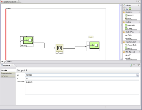
It consists of three main areas:
the canvas—the large area where routes are drawn
the pallet—the area on the right from which nodes are selected
the properties editor—the area on the bottom where you enter the configuration properties for the selected node
The canvas is the area of the editor where most of the work is done. It contains the visual representation of one or more routes. Routes are delineated by a red border and are made up of one or more connected nodes.
Nodes are placed on the canvas by dragging them from the pallet. Once a node is placed on the canvas, it's properties can be edited in the property editor. To edit a node's properties, you select it on the canvas and the property editor is configured for that node.
The nodes can be connected by selecting a node and dragging the cursor to the next node in the route's flow. If the target node is not valid, the editor will not let you drop the connector on it.
![[Tip]](imagesdb/tip.gif) | Tip |
|---|---|
The Source tab on the bottom of the canvas will allow you to see and edit the generated XML. |
The pallet contains all of the tools needed to draw a route on the canvas. It is divided into sections based on the tool's functions:
top row—the tools across the top of the pallet are drawing tools. The arrow is the most commonly used tool and is for selecting items on the canvas. The green square is the new route tool.
Endpoints—nodes that can be used as the starting and ending points of a route
Routing—nodes that direct the flow of messages based on specified criteria
Control Flow—nodes that function like control functions in a programming language. For example, they define loops or handle error conditions.
Transformation—nodes that change the contents of a message as it passed through a route
Miscellaneous—nodes that control the execution environment of the route. For example, one node specifies the number of threads available.
The properties editor is used to configure the nodes in a route. Its contents depend on the selected node. Each type of node has a set of properties that can be or must be set. The properties editor is populated with fields for the properties applicable to the selected node.
The properties editor makes it clear when required properties are not set. Any required property that is not set will have a red X placed next to it. The top row of the properties editor will also display a message informing you of how many required properties remain to be set.
| Tip |
|---|---|
The properties editor has a Documentation tab that displays a reference for the component configuration. |
 |  |  |
 |
