Developer Guide to the BPEL Designer: Using the Palette Elements
Contributed by Bob May, maintained by Irina Filippova
December 2007
Contents
Developer Guide to the BPEL Designer
Using the Invoke Element
The Invoke element enables the business process to invoke a one-way or request-response operation on a portType offered by a partner. It enables the business process to send messages to partners. The operation is defined in the partner's WSDL file.
Usage
- In the Design view, drag the Invoke element from the Palette to the diagram.
-
Perform one of the following procedures to associate the Invoke element with a Partner Link element:
-
Directly draw a message flow from the Invoke element to the target Partner Link.
-
Double-click the Invoke element. A dialog opens where you can examine or change the following:
-
The name of the Invoke element.
-
The partner link that is invoked.
-
The operation associated with the Invoke element.
-
The input variable associated with the Invoke element.
-
The output variable.
Both input and output variables can be created or browsed through this dialog.
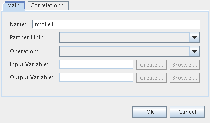
In the Property Editor dialog box, you can either create a variable or use an existing variable to hold input and output data. Click the Create button to create a variable for the Invoke element, and click Browse to choose an existing variable.
Note that when you click the Browse button, the Input Variable Chooser or the Output Variable Chooser dialog boxes opens. In these dialog boxes, a checkbox with the option to show variables with appropriate types appears. This checkbox restricts the list of available variables to those which are of the proper type for the activity you are configuring. In this way the Design view helps you develop valid BPEL code.
Correlations
Correlation sets on invoke activities, which deal with outbound operations, are used to validate that outgoing messages contain data which is consistent with the data contained within specified correlation set instances.
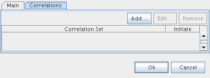
The Correlations tab in the Invoke Property Editor dialog box enables you to examine or specify a correlation set.
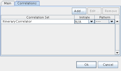
The tab shows:
-
Names of correlation sets
-
The initiation of a correlator
-
The pattern associated with the correlation
You can add a correlation set by clicking the Add button.
Defining a Correlation Set and Adding a Correlation Set to an Element
Correlation is the means by which the BPEL runtime tracks conversations between a particular process instance and corresponding instances of its partner services. You can think of correlation as a primary key that is used by the BPEL runtime to correlate incoming and outgoing messages and route them accordingly.
A correlation set is a collection of properties used by the BPEL runtime to identify the correct process to receive a message. Each property in the correlation set may be mapped to an element in one or more message types through property aliases.
To define a correlation set, messages from partner services must have properties and property aliases defined in the partner WSDL file. You can add properties and property aliases to a WSDL file using the WSDL Editor or the Navigator.
After properties and property aliases are added to the WSDL file associated with the process, you can define correlation sets for the Process element.
To define a correlation set:
-
In the Design view, right-click the Process element and choose Add > Correlation Set. The Add Correlation Set dialog box appears.
-
Change the name for the correlation set and click Add to add properties.
-
In the Property Chooser dialog box, expand the WSDL file node, select a property to add to the set, and click OK.
Note that by default, the Property Chooser dialog box only shows those files that have already been referenced in the process. However, the project may contain other .wsdl and .xsd files which have not yet been imported into the process. If you select a property that is defined in a non-imported file, the IDE will automatically add the required import to the BPEL process.
After defining the correlation set as outlined above, add the correlation set to Invoke, Receive, or Reply elements. You can also associate a correlation set with the On Message branch of a Pick activity and with an On Event element within an Event Handlers container.
The following shows a correlation set as seen in the Navigator.
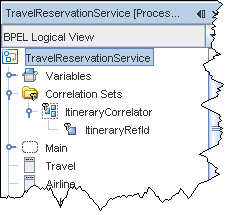
To add a correlation set to an element:
-
In the Design view, double-click an element (Invoke, Receive, Reply, the On Message branch of Pick or the On Event element within an Event Handlers container).
-
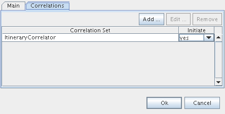
In the Property Editor dialog box, select the Correlations tab and click Add.
-
In the Choose a Correlation Set dialog box, select the correlation set and click OK.
- Choose the initiate attribute for this correlation set from the Initiate drop-down list. You can select one of the following options:
- Yes. The activity must attempt to initiate the correlation set.
- Join. The activity must attempt to initiate the correlation set if the correlation set is not yet initiated.
- No. The activity must not attempt to initiate the correlation set. This is the default option.
- Specify the message pattern, which can be request, response, or request-response operations.
- Click OK.
For more information about correlation sets, properties, and property aliases, see the
Using Correlation Sets, Properties, and Property Aliases in BPEL tutorial.
top
Using the Receive Element
The Receive element allows the business process to do a blocking wait for a particular message to arrive.
Usage
- In the Design view, drag the Receive element from the Palette to the diagram.
-
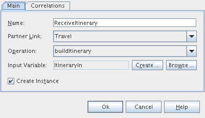
Double-click the Receive element (or right-click it and choose Edit) to configure its properties. Here the example is provided for the Travel Reservation Service sample:
-
The name of the Receive element (ReceiveItinerary).
-
The partner link (Travel).
-
The operation associated with the Receive element (buildItinerary).
-
The input variable to the Receive element (ItineraryIn).
Select Browse for the Input Variable to open the Input Variable chooser, where you can choose other variables associated with this process. Select Create to create a new variable.
-
Create Instance. If selected, an instance of the BPEL process starts when an associated message arrives. Note that if the Receive activity is the first activity in your business process, the Create Instance checkbox must be selected.
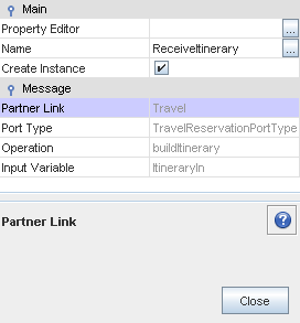
- Right-clicking the Receive element and choosing Properties opens a Properties window, which, in addition to the items listed in the Receive Property Editor, includes the following::
-
Port Type. The value of the Port Type field is filled in when you specify the partner link and operation.
Correlations
The Correlations tab in the Receive Property Editor dialog box enables you to examine or specify a correlation set.
The tab shows:
- Names of correlation sets
-
The initiation of a correlator
You can add a correlation set by clicking the Add button. For more information, refer to Defining a Correlation Set and Adding a Correlation Set to an Element.
top
Using the Reply Element
Use this activity to return a message from the process to the same partner that initiated the operation. The combination of Receive and Reply activities creates a request-response operation.
This activity is used in a synchronous (request/response) operation, and specifies the same partner, port type and operation as the Receive activity that invoked the process.
Usage
-
In the Design view, drag the Reply element from the Palette to the diagram.
-
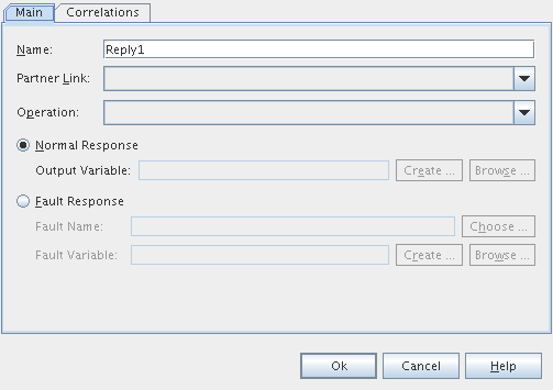
Double-click the Reply element (or right-click and choose Edit) to open a Property Editor dialog box for the Reply element. In this dialog box, you can specify the following:
-
The name of the element.
-
The Partner Link.
-
The operation.
-
Type of response: Normal Response or Fault Response.
-
Select Normal Response if the Reply element is to be used for the normal response message type. Optionally, specify the output variable: either create a new output variable or browse for an existing variable.
-
Select Fault Response if the Reply element is to be used to send a fault message. Choose a fault name and, optionally, specify the fault variable: either create a new fault variable or browse for an existing variable.
-
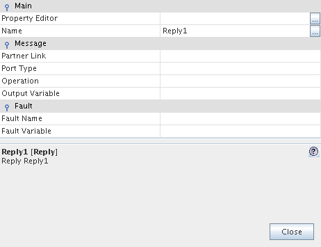
Right-clicking the Reply element and choosing Properties opens a Properties window, which, in addition to the items listed in the Property Editor dialog box, includes the following:
-
Port Type. The value of the Port Type field is filled in when you specify the Partner Link and operation.
Correlations
The Correlations tab in the Reply Property Editor dialog box enables you to examine or specify a correlation set.
The tab shows:
- Names of correlation sets
-
The initiation of a correlator
You can add a correlation set by clicking the Add button. For more information, refer to Defining a Correlation Set and Adding a Correlation Set to an Element.
top
Using the Partner Link Element
Partner Link elements identify the parties that interact with your business process. Each link is defined by a partner link type and a role name.
Partner Link Types and Roles
The type determines the relationship between a process and its partners by defining the roles played by each service in a conversation. The relationship is further determined by specifying the port type provided by each service to receive messages. Each role specifies one port type in the WSDL file.
Roles determine the conversational aspect of this process or its partner. You use a single role for a synchronous operation as the results are returned using the same operation. You use two roles in an asynchronous operation as the partner role switches during a callback.
It is easy to confuse partner links and partner link types, however:
-
Partner link types and roles are special WSDL extensions defined by the BPEL specification. As such, they are defined in WSDL files, not in the process BPEL file.
-
Partner Link is a BPEL 2.0 element. It is defined in the process BPEL file.
Partner link types are prerequisites to the Partner Link element definition. A Partner Link element can only be defined by referring to a particular partner link type and role which, as mentioned, must be defined in a WSDL file.
Usage
To add the Partner Link element to the BPEL process, do one of the following:
-
Drag the Partner Link element from the Palette to the diagram.
-
Drag a WSDL file node from the same project in the Projects window to the diagram.
-
Drag a WSDL file node from a different project in the Projects window to the diagram.
-
Drag a web service node from an EJB project or a Web Application project in the Projects window to the diagram.
Note: When you drag the web service node, the BPEL Designer retrieves the WSDL file from the Application Server. To successfully retrieve the WSDL file, the Application Server has to be running and the web service project must be deployed.
When you drag the Partner Link element, a WSDL file node, or a web service node to the diagram, the Partner Link Property Editor appears.
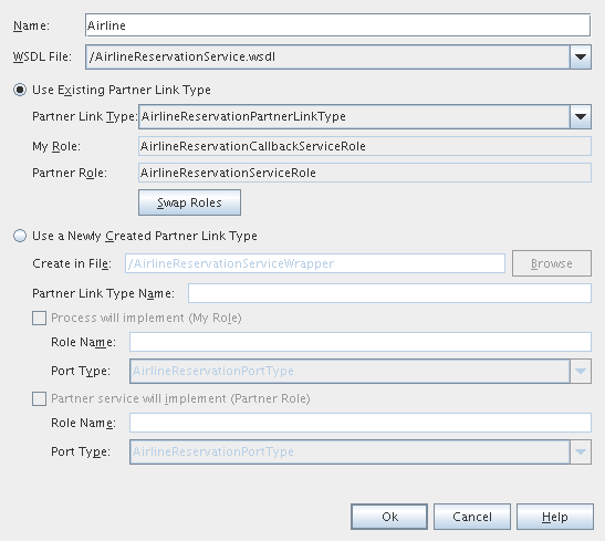
The Partner Link Property Editor
The Partner Link Property Editor dialog box enables you to establish partner links for your BPEL processes.
The Partner Link Property Editor is invoked by double-clicking a Partner Link element on the diagram, or right-clicking the Partner Link element and choosing Edit. The Partner Link Property Editor also appears when you drag the Partner Link element, a WSDL file node, or a web service node to the diagram.
With the Partner Link Property Editor, you can specify:
-
The Partner Link name
-
The WSDL file associated with the Partner Link
Further on you can choose whether to use the existing partner link type or create a new partner link type.
If the WSDL file you selected contains partner link types, the Use Existing Partner Link Type option is selected and the Partner Link Type drop-down list is populated with the partner link types found in the WSDL file. You can use one of the existing partner link types or select the Use a Newly Created Partner Link Type option to create a new partner link type.
If the WSDL file does not contain partner link types, the Use a Newly Created Partner Link Type option is selected.
-
Use Existing Partner Link Type
- Choose the partner link type from the drop-down list. The My Role and/or Partner Role fields are filled in automatically.
- To swap the roles of the business process itself (My Role) and the partner (Partner Role), click the Swap Roles button.
- Use a Newly Created Partner Link Type
- Specify the WSDL file in which to add a partner link type. You can do one of the following:
- Add the partner link type to the wrapper WSDL file, as suggested by the IDE in the Create in File field by default. If you choose this option, the IDE will automatically create the wrapper WSDL file in your project structure. You can use wrapper WSDL files when the original WSDL file is read-only or when you do not want to modify the original WSDL file. The original WSDL file will be imported to the newly created wrapper WSDL file.
- Add the partner link type to a WSDL file within your project. Click Browse and locate the WSDL file in which to add the partner link type.
- Specify the partner link type name.
- Specify the role of the business process itself (My Role) and/or the role of the partner (Partner Role) as follows:
-
Select the appropriate checkbox.
-
Specify the role name.
- Choose the port type from the drop-down list.
You can also review and modify the Partner Link's properties in the Properties window invoked by right-clicking the element and choosing Properties.
top
Using the Empty Element
The Empty element has no operation associated with it. It is usually used as a placeholder within a process, to catch and suppress faults, or to help synchronize actions within a flow activity that are executed concurrently.
The Empty element can be used when someone else will be implementing a business process, or when the activities within a flow activity need to be synchronized.
Usage
Drag the Empty element from the Palette to the diagram.
top
Using the Wait Element
Use a Wait element to specify a wait condition based on a unit of time or a duration.
Usage
Drag the Wait element from the Palette to the diagram. Like other elements, it must be placed in the correct position in the process flow; otherwise you will not see the element in the diagram.
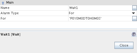
Right-click the element in the diagram and choose Properties to invoke a Properties window. Using the Properties window, you can specify:
-
The name of the element.
-
The alarm type. The available options are:
-
For – specifies a duration for the process to wait
-
Until – specifies the time until which the process is delayed.
-
For/Until. Clicking the ellipsis button (...) invokes a dialog box where you specify the time in accordance with the selected expiration type.
top
Using the Throw Element
Use this activity to signal an internal fault.
Usage
In defining the properties of this element, you can specify a fault name and a fault variable. These details can then be passed onto a fault handler that is configured to deal with this kind of exception.
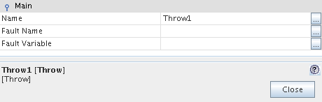
Throw Element Properties
The properties of the Throw element can be configured via the Properties window invoked by right-clicking the element and choosing Properties. The options are:
-
Name
-
Fault Name. Clicking the ellipsis button (...) invokes the Fault Name dialog box where you can choose the fault from the list that includes faults defined in WSDL files.
You can use the WSDL Editor to add fault definitions to the WSDL file. For more information, see the
Configuring Port Types Using the WSDL View section of the Developer Guide to the WSDL Editor.
-
Fault Variable. Click the ellipsis button (...) to specify the name of the variable, already declared in the BPEL file, that will contain the fault message.
top
Using the Assign Element
The Assign activity assigns values to variables. You use the Assign element to copy data from one variable to another, construct and calculate the values of expressions, and store new data in variables. Expressions are required to perform simple computation or operate message selections, properties, and literal constants to produce a new value for variables. The Assign activity can contain one or more elementary assignments.
Usage
Use the BPEL Mapper to define the copy rules for the Assign activity or add expressions. For more information, refer to the Assign Activity Scenario section of the guide.
The BPEL Mapper windows opens when you select the Assign activity on the diagram. If this window is not visible, you can invoke it manually, by choosing Window > Other > BPEL Mapper from the main menu.
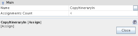
Assign Element Properties
The Properties window of the Assign element, invoked by right-clicking the element and choosing Properties, contains two properties:
-
Name. This is the name of the element
-
Assignments Count. This is the number of assignment rules specified for the element.
top
Using the Flow Element
Use the Flow element to define a set of activities that will execute concurrently (in parallel).
The Flow activity is a structured activity, containing other activities separated into individual control paths or branches. You can embed as many paths in the activity as you want, and they will all be executed simultaneously.
During execution, each path is executed concurrently, and the activities on each are executed in the order in which they appear, unless they are the source of a link. When the activities are the source of a link, the condition of the link and the join condition of the activity must be evaluated. If the link conditions that lead to an activity conflict with those of its join condition, then a fault is thrown on that activity.
Usage
In the Design view, drag the Flow Element from the Palette to the diagram.
Drag an element to the placeholder inside the Flow element. If you add another element into the same branch of the Flow element, the elements within a branch are automatically wrapped in the Sequence element.
Adding Branches to the Flow Element
You can add one or more branches to the Flow element. The Flow element has a special user interaction style. It always shows a placeholder for the next branch that you might wish to add. To add a new branch, drag an element from the Palette to the immediately available "next branch" placeholder.
Changing the Order of Elements inside Flow
To change the order of activities inside the Flow element:
- In the Design view, right-click the Flow element and select Change Order.
- Select an element and use the Move up or Move down buttons to change the position of the element inside the container.
top
Using the Sequence Element
Use the Sequence element to nest a series of activities into your process. The activities within a sequence will execute in strict sequential order. Process execution returns to the business process when the last activity within the nest has completed.
Usage
Drag the Sequence element from the Palette to the diagram.
Adding Child Activities to the Sequence
You can add one or more child activities to the Sequence. The Sequence element has a special user interaction style. It always shows one or more valid placeholders for the next activity that you might wish to add. To add a new child activity, drag and drop an element from the Palette onto the immediately available next or previous activity placeholder.
Changing the Order of Elements inside Sequence
To change the order of activities inside the Sequence element:
- In the Design view, right-click the Sequence element and select Change Order.
- Select an element and use the Move up or Move down buttons to change the position of the element inside the container.
top
Using the If Element
The If activity supports conditional behavior of a business process instance. The If activity consists of conditional branches defined by the If and Else If elements, followed by an optional Else branch. The conditions on If and Else If branches are evaluated in the order they appear. During execution, the first branch whose condition holds true is taken and provides the activity specified for the If activity. In other words, if there are several Else If branches whose conditions hold true, only the first of them will be executed.
If none of the branches evaluates to true, then the Else path is chosen. If the Else branch is not explicitly specified, this branch is considered to contain an Empty activity. The If activity is complete when the activity of the selected branch completes.
Usage
-
In the Design view, drag the If element from the Palette to the diagram.
-
Select the If element on the diagram. The BPEL Mapper window appears at the bottom of the IDE. If the BPEL Mapper window does not appear, right-click the If element and select Show BPEL Mapper.
-
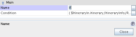
Specify the condition for the If element using the BPEL Mapper. For more information, refer to the If Activity Scenario section of the guide. You can also specify the condition manually in the Properties window, invoked by right-clicking the element and choosing Properties.
-
(Optional) In the Properties window, enter the name for the If element.
-
Add the element that will be executed if the condition is true into the If element. Configure the nested element. If you add another element into the If element, the nested elements are automatically wrapped in the Sequence element.
-
Add other branches (Else If and Else) as described below.
Adding an Else If Branch to the If Element
-
Right-click the If element and choose Add Else If.
-
Add an activity to the Else If that will be executed if the condition defined for this Else If element is true. To define a condition, use the BPEL Mapper.
-
(Optional) Add more Else If activities by choosing Add Else If and add activities to them.
Adding an Else Branch to the If Element
Drag the activity you want to be executed on the Else branch onto the connector path marked with a slash mark. Configure the nested activity.
Reordering Else If Branches
In the Design view, drag the Else If branch that you want reordered and drop it onto the placeholder that appears next to another Else If branch.
top
Using the Pick Element
The Pick element blocks the process and waits until one of the specified events occurs. After the specific event occurs, the activity associated with this event is performed. The possible events are the arrival of a message or a timer-based alarm. The occurrence of the events is mutually exclusive. If more than one of the events occurs, then the selection of the activity to perform depends on which event occurred first.
The Pick activity provides two branches, On Message and On Alarm. The branch whose condition is satisfied first (i.e. a message is received or the specified timer expires) is executed. When you add a Pick element to your diagram, it automatically includes one On Message statement in which you specify the properties of the message that the process awaits from a partner service. Each Pick element must include at least one On Message statement. The On Alarm branch contains a timer you can use to specify how long the process is to wait.
Usage
-
In the Design view, drag the Pick element from the Palette to the diagram.
-
For the On Message branch, configure the properties of the message for which the process is waiting. The configuration is similar to that of the Receive element.
-
From the Palette, drag the activity that will be executed and place it inside the On Message branch. Configure the activity's properties.
-
(Optional) Add more On Message branches by choosing Add > On Message from the pop-up menu and configure them as described above.
-
(Optional) Add one or more On Alarm branches following the procedure below.
Adding an On Alarm branch
-
Right-click the Pick element and choose Add > On Alarm from the pop-up menu.
-
Configure the timer via the Properties window, invoked by right-clicking the element and choosing Properties. The available options are:
-
Alarm Type – used to choose the type of alarm. The type can be one of the following:
-
For – specifies a duration for the process to wait.
-
Until – specifies a deadline for the process.
-
For/Until – used to configure the deadline or the duration for the chosen alarm type. Click the ellipsis button (...) to specify the time. You can also use the BPEL Mapper.
-
Find the activity you want executed after the time expires, and drag it from the Palette to the placeholder inside the On Alarm element.
-
(Optional) Add one or more On Alarm branches as described above.
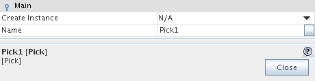
Pick Element Properties
The Properties window for the Pick element, invoked by right-clicking the element and choosing Properties, includes the following fields:
-
Create Instance. If set to yes, a new process instance will be created when the specified event occurs. If you do not plan to start a new process instance, keep the default N/A value.
-
Name. This is used to specify the name for the element.
top
Using the Scope Element
The Scope activity is essentially a collection of child activities that can have their own Variables, Fault and Event Handlers, and correlation sets. The Scope activity provides the behavior context for the child elements. The attributes defined for a parent Scope have local visibility inside this Scope. For example, the variables declared for a Scope are visible only inside that Scope and all nested Scopes. These variables can then be used for the child activities of this Scope.
Usage
-
In the Design view, drag the Scope element from the Palette to the diagram.
-
Right-click the element and choose Add from the pop-up menu to add the following:
- In the Design view, drag elements from the Palette and place them inside the Scope element.
-
Configure the elements.
-
(Optional) Specify the name of the Scope element in the Properties window, invoked by right-clicking the element and choosing Properties.
Variables
Variables in BPEL programming function just as they do in other programming languages: they hold temporary values, form parts of expressions, or are passed
as parameters to external partners. Normally, you need a variable for every message sent to or received from a partner service. The BPEL Designer supports the following types of variables:
- WSDL Message type. These variables correspond to web service message types that are defined in WSDL files imported by the process. In a BPEL file (.bpel), these variables must specify a value for the messageType attribute. Message type variables are used to hold data in interactions between the process and its partner services.
- XML Schema type. These variables correspond to simple or complex XML Schema data types. The XML schema types themselves are defined in XML Schema files (.xsd) or in WSDL files that are imported into the process. In a BPEL file, variables of this type must specify a value for the type attribute.
- XML Schema element. These variables correspond to XML Schema elements.The XML schema elements themselves are defined in XML Schema files (.xsd) or in WSDL files that are imported into the process. In a BPEL file, variables of this type must specify a value for the element attribute.
- Built-in type. Variables of this type are standard simple types defined in the XML Schema specification.
Global and Local Variables
The variables defined at the Process root are global variables, which have a global visibility throughout the entire process. The variables defined within a particular Scope are visible only inside that Scope and all nested Scopes. These variables are called local variables. A variable defined for an inner Scope element can hide an upper defined variable of the same name.
The name of a variable must be unique among the names of all variables defined within the same Scope.
To define a variable:
- Right-click the Process or Scope element and select Add > Variable.
- In the Create New Variable dialog box, name the variable. The name should be unique within this Scope element.
- Expand the node corresponding to the type of the new variable and select its type. You have the following options:
- Built-in Types. Expand the Built-in Types node, select the type's name, and click OK.
- Message Type. Expand a .wsdl file node, select a message type and click OK.
- XML Schema. Expand an .xsd file node or a .wsdl file that contains an embedded schema. Expand the Global Complex Type, Global Simple Type, or Global Elements Simple nodes, select the appropriate type, and click OK.
For your convenience, global types of variables are displayed in bold.
- (Optional) Clear the Show Imported Files Only checkbox to view the contents of non-imported WSDL and XML schema files.
- Click OK.
By default, the Create New Variable dialog box only shows those files that have already been referenced in the process. However, the project may contain other WSDL and XSD files which have not yet been imported into the process. If you select a type for the new variable that is defined in a non-imported file, the IDE will automatically add the required import to the BPEL process.
You can also add variables from the Navigator window. To add a variable, select BPEL Logical View in the Navigator, expand your BPEL Module project's node, right-click the Variables node and choose Add Variable.
To edit a variable:
- In the Navigator window, select BPEL Logical View.
- Expand BPEL Module project's node > Variables and double-click the variable you want to edit.
- In the Property Editor dialog box for the variable, change the variable type and name.
- Click OK.
top
Using the While Element
Use the While element to repeatedly execute one or more activities as long as specific conditions are in place at the beginning of each iteration. This element contains other elements that are repeated while success criteria you specify are met. If the condition you specify leads to false, none of the activities listed will be executed.
Note: the While element first checks the validity of the condition and then executes the iterative activity. Conversely, the Repeat Until element first executes the activity and then checks the validity of the condition.
Usage
- In the Design view, drag the While element from the Palette to the diagram.
- Drag an activity that will be repeatedly executed and place it inside the While element. If needed, configure the activity's properties.
-
Use the Properties window to specify the name and condition of the While element. You can enter the condition manually or use the BPEL Mapper to generate the condition for you. To open the BPEL Mapper window, choose Window > BPEL Mapper or right-click the While element on the diagram and choose Show BPEL Mapper.
top
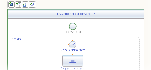
Using the Process Element
The Process element is already present in your diagram. The New Project wizards always create a skeletal BPEL file that contains at least a process element. Therefore, the Process element is not part of the Palette. The Process element is assumed to be present, as it is the minimum requirement for a BPEL file.
The following screenshot shows the representation of a process in the Travel Reservation Service sample.
Usage
-
Right-click the Process element and choose Add from the pop-up menu to add the following:
-
Specify the name and the target namespace of the Process element in the Properties window, invoked by right-clicking the element and choosing Properties.
Processes
A BPEL process can be synchronous or asynchronous. A synchronous BPEL process blocks the client (the one which is using the process) until the process finishes and returns a result to the client. An asynchronous process does not block the client. Rather it uses a callback to return the result (if any). Usually we use asynchronous processes for longer-lasting processes and synchronous for processes that return a result in a relatively short time. If a BPEL process uses asynchronous web services, the process itself is usually also asynchronous.
top
Using the Repeat Until Element
Use the Repeat Until element to repeatedly execute one or more activities as long as specific conditions are in place after the execution of each iteration. This element contains other elements that are repeated until the success criteria you specify are met. If the condition you specify leads to true, the activities listed will be executed once.
Note: the Repeat Until element first executes the iterative activity and then checks the validity of the condition. Conversely, the While element first checks the validity of the condition and then executes the activity.
Usage
- In the Design view, drag the Repeat Until element from the Palette to the diagram.
- Drag activities that will be repeatedly executed and place them inside the Repeat Until element. If needed, configure the activity's properties.
-
Use the Properties window to specify the name and condition of the Repeat Until element. You can enter the condition manually or use the BPEL Mapper to generate the condition for you. To open the BPEL Mapper window, choose Window > Other > BPEL Mapper or right-click the Repeat Until element on the diagram and choose Show BPEL Mapper.
top
Using the For Each Element
Use the For Each element to repeatedly execute its contained scope activity exactly N+1 times where N equals the Final Counter Value minus the Start Counter Value.
Usage
-
In the Design view, drag the For Each element from the Palette to the diagram.
-
Add elements that will be repeatedly executed from the Palette into the For Each element. The elements that you add are automatically wrapped into the Scope element.
-
Right-click the For Each element and choose Properties to open its Properties window.
The Properties window for the For Each element includes the properties listed below.
-
Name. Specifies the name of the For Each element.
-
Counter Variable Name. Declares the counter variable name.
-
Start Counter Value. Sets the start counter value. Use the BPEL Mapper to generate an integer value expression.
-
Final Counter Value. Sets the final counter value. Use the BPEL Mapper to generate an integer value expression.
When the For Each activity is started, the expressions in Start Counter Value and Final Counter Value are evaluated for the first and only time. That is, once the two values are returned they remain constant for the lifespan of the activity. If the Start Counter Value is greater than the Final Counter Value, then no iteration will be performed.
-
Completion Condition (Optional). Specifies an integer value expression. After execution of each directly enclosed activity, the number of completed activities is checked against this value. When the number of completed activities equals the value of the specified expression, no further activities are started. When the expression value is greater than the available number of iterations, then no iteration will be started.
-
Count Completed Branches Only (Optional). If this checkbox is selected, it tells the runtime to only count the branches that have completed successfully. If this checkbox is cleared, all branches, completed successfully or unsuccessfully, will be counted.
top
Using the Exit Element
Use this activity to halt the execution of an activity or a process: either within the process, within a structured activity, or within a handler.
Usage
In the Design view, drag the Exit element from the Palette to the diagram.
Note: The BPEL runtime does not support Exit within the Flow and On Alarm elements, or within the On Event child of the Event Handler element.
top