The Greenbone GSM appliance can be connected to other systems.
This chapter covers the possible options.
Some systems have been integrated already into the GSM by Greenbone Networks.
This includes the verinice ITSM system, the Sourcefire IPS Defense Center and the Nagios Monitoring System.
A couple of further integrations such as Palo Alto, are described in chapter Scanners.
The following sections will instruct in these possibilities and give instructions for the configuration.
22.1. Integration with third-party vendors
The GSM has numerous interfaces that allow for the communication with third-party vendors.
This section covers the options for an integration and connection with other systems.
Hereby the GSM offers the following interfaces:
- OpenVAS Management Protocol (OMP)
- The OpenVAS Management Protocol allows to completely remote control the GSM appliance.
The protocol supports the creating of users, creating and starting of scan tasks and downloading reports, and so on.
- Connecting additional scanners via OSP
- The OpenVAS Scanner Protocol (OSP) is a standardized interface for different vulnerability scanners.
Arbitrary scanners can be integrated seamless into the GSM vulnerability management.
Controlling the scanners and handling the results works in the same way for all scanners.
- Report Format
- The GSM can present the scan results in any format.
To do so the GSM already comes with a multitude of pre-installed report formats.
Additional report formats can be downloaded from Greenbone or developed in collaboration with Greenbone.
- Alert via Syslog, E-Mail, SNMP-Trap or HTTP.
- Automatic result forwarding through connectors.
- These connectors are being created by Greenbone, verified and integrated into the GSM.
- Monitoring via SNMP
- On the web site http://docs.greenbone.net/API/SNMP/snmp-gos-3.1.en.html provides the current MIB file (Management Information Base).
MIB files describe the files that can be queried by SNMP about the equipment.
22.1.1. OSP Scanner
The OpenVAS Scanner Protocol resembles the OpenVAS Management Protocol (OMP, see chapter OpenVAS Management Protocol).
It is XML based, stateless and does not require a permanent connection for communication.
The design allows for embedding of additional scanners seemlessly into GSM.
The GSM comes with a number of OSP scanners on board, see chapter Scanners.
The open format allows to develop arbitrary own OSP scanners.
Greenbone provides the protocol documentation and a base framework for programmers, see chapter OpenVAS Scanner Protocol.
22.2. Verinice
Verinice (see http://verinice.org/en/) is a free OpenSource Information Security Management System (ISMS), developed by the company SerNet (see http://sernet.de/en/).
Verinice is suitable for:
- vulnerability remediation workflow
- implementing the BSI IT-Baseline Protection Catalogues
- performing risk analysis based on ISO 27005
- operating an ISMS based on ISO 27001
- performing an IS assessment per VDA specifications
- proof of Compliance with standards such as ISO 27002, IDW PS 330
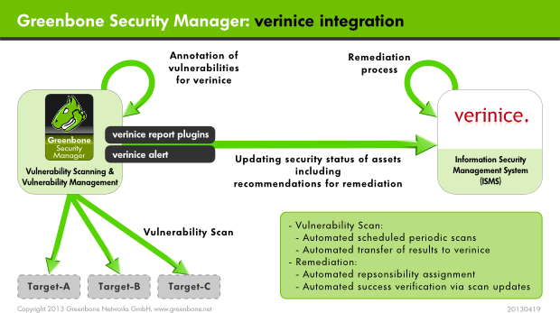
The Greenbone Security Manager can support the modelling and implementation of IT Baseline Protection as well as the operation of an ISMS.
For this Greenbone offers two report plugins for the export of data from the GSM into verinice:
Verinice-ISM containing all scan resultsVerinice-ITG containing the scan results of a BSI IT-Baseline Protection scan
The option exists to transfer data completely automated from the Greenbone Security Manager to verinicePRO, the server extension of verinice.
Following the manual import of reports from the GSM in the free verinice version is covered.
For support with the use of the connector please contact SerNET or Greenbone.
22.2.1. IT Security Management
The report plugin for verinice is pre-configured and is available as Verinice-ISM.
With this report plugin Greenbone supports the vulnerability remediation workflow in verinice.
Hereby the notes (notes objects, see section Notes) of the scan results play a central role for the Verinice-ISM plugin.
Verinice uses the notes to create objects for processing.
If there are no notes in a task only the assets will be imported as well as the complete vulnerability report.
Exclusively such vulnerabilities that have a note will be imported by verinice as vulnerabilities.
This allows controlling the import in fine detail.
Note
Why are only vulnerabilities transferred where a note is attached?
Within the entire security process for vulnerabilities, there must be a single point where the decision is made which vulnerability must be resolved and which are tolerable.
This decision is made in the vulnerability management, by tagging the vulnerabilities accordingly.
The remediation workflow targets at solving any of the managed issues.
Within the remediation workflow it is not allowed to decide about tolerating an issue.
Afterwards the report needs to be saved as Verinice ISM-Report.
A .vna file will be created.
This is a zip file containing the data of the GSM scan.
Start verinice to import.
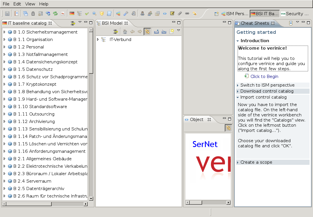
In verinice open the ISM perspective.
Import the catalogue Implementation Assistance for ISO27001.
Create an organization.
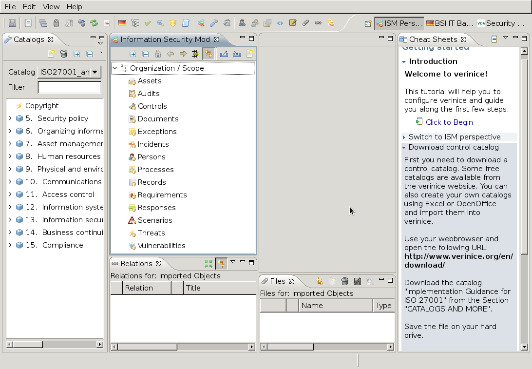
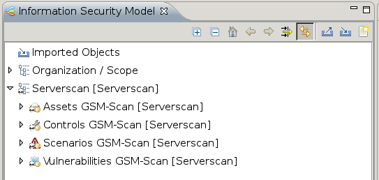
Afterwards the screen should look like figure Verinice offers an ISM perspective..
22.2.1.1. Importing of the ISM Scan
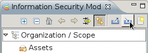
In the verinice interface chose the import option in the Information Security Model.
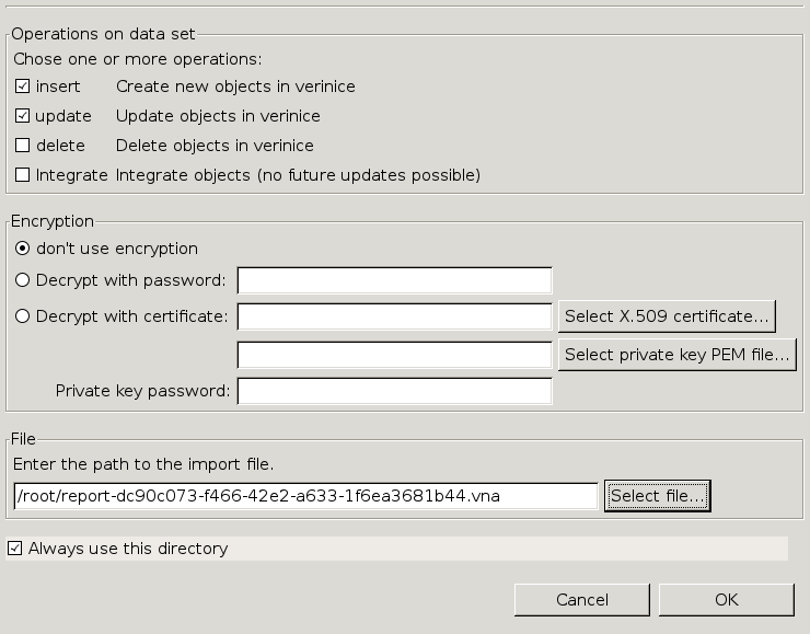
Now select your ISM report.
The remaining parameters can be kept with their default settings.
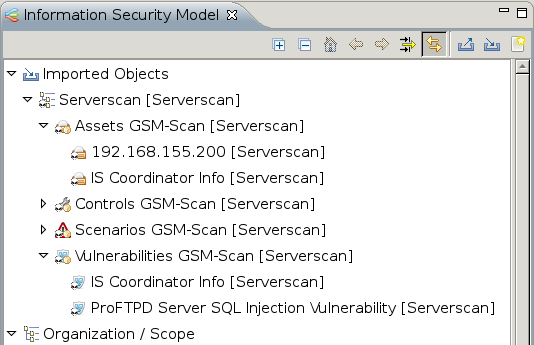
The results of the ISM report were imported and can be unfolded in Vernice.
Thereby only the results were imported that had notes included in the GSM report.
The process to track vulnerabilities for the imported organization can be separated into two sub processes:
- Creation of tasks
- Remediation of vulnerabilities
22.2.1.2. Creation of Tasks
Before creating tasks the data for the organization must be prepared with the following steps:
After the first import of an organization it must be moved to the top level from the group of imported objects.
Cut the organization and paste it back into the top level again.
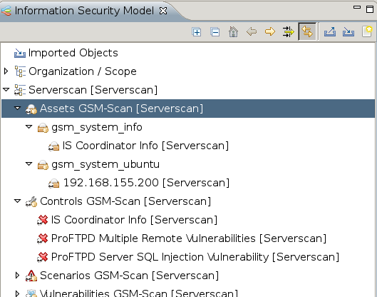
The assets and controls must be grouped.
In the context menu in the top most asset and control group select the option Group with Tags...
In figure The assets have already been grouped. this has already been done.
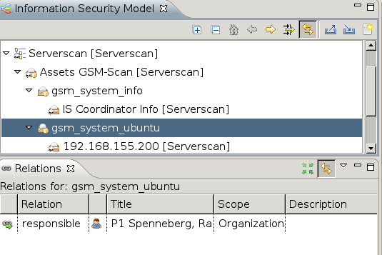
All assets groups must be assigned a person responsible.
Assign a person to one or more asset groups.
Hereby create the person and assign them with drag&drop.
The successful assignment is being displayed in the Relations window.
After all the asset groups have been assigned to a person responsible, the process to remediate the vulnerabilities can be started from the context menu of the organization.
Select from the context menu of an organization the task Greenbone: Start Vulnerability Tracking.
First it will be verified if all asset groups are assigned to a person and controls are grouped.
The result of the verification will be displayed in a dialog.
The user can continue and create tasks or cancel the creation.
22.2.2. IT Security Baseline
Greenbone provides a special configuration (IT Security Baseline scan including discovery for verinice) as well as an IT Security Baseline report plugin (Verinice ITG), which allows for the export of a report suited for verinice.
For optimum results the scan configuration needs to be imported. The report plugin is now shipped with the GSM. A manual import is not required anymore.
For optimum results in the scan it is helpful to perform an authenticated scan (see section Authenticated Scan).
As soon as the scan is completed export it in the verinice ITG format.
A file with the extension .vna is being created.
This is a ZIP archive in which the results of the scans are stored.
This file can be loaded by verinice directly.
Following for clarity purposes a scan is being used with only one host.
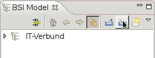
Open verinice and change into the IT Security Baseline start perspective (see figure Verinice opens the already modelled IT bond.).
If no IT bond has been created yet the middle view will still be empty.
22.2.2.1. Importing of the ITG Scan
In the verinice interface select the import function in the IT Security Baseline model.
Now select the ITG report.
The remaining parameters can be kept with their default settings.
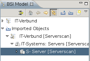
The results of the ISM report were imported and can be unfolded in Vernice.
The imported objects are named by the target in the GSM or their IP address.
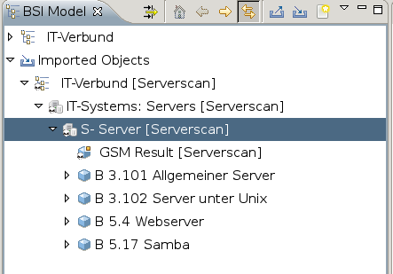
Every imported object has a sub-object GSM result with the activity results of the scan.
Now the IT Security Baseline modules can be added.
For this select a server by right clicking on it.
In the context menu select Greenbone: Automatically assign components.
Verinice now will be choosing the appropriate components to model the system based on the tags set by the GSM.
Now the results of the scans can be added into the control catalogue.
Hereby select the server object and select the option Greenbone: Automatic Base Security Check from the context menu.
22.3. Nagios
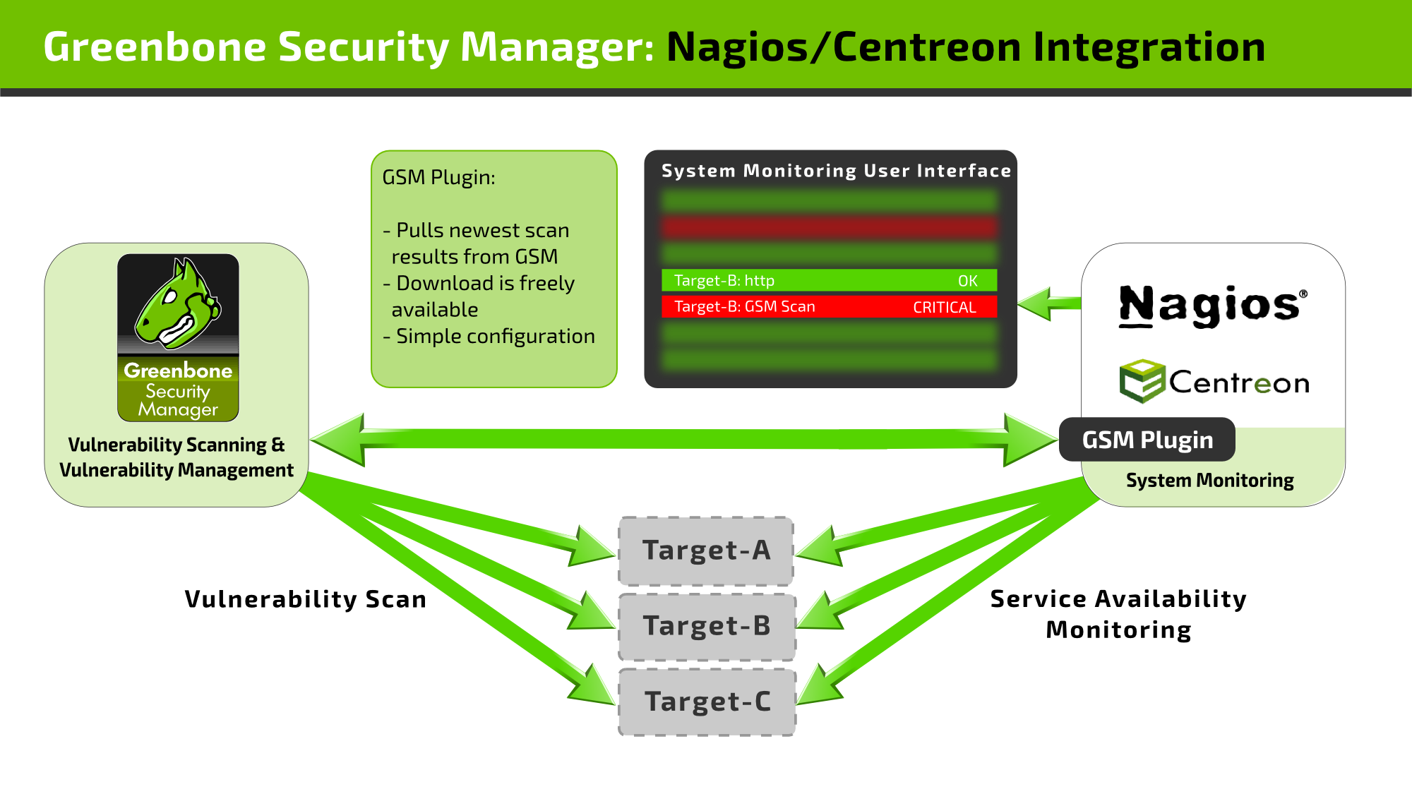
Nagios can integrate the scan results in its monitoring tasks as additional test.
In this case the scanned systems are automatically matched with the monitored systems. With this the scan results are eventually available for the alert rules and other processes of Nagios.
When linking Nagios with GSM, Nagios will assume the controlling role. Nagios regularly and automatically retrieves the newest scan results from Greenbone Security Manager. This is done via a Nagios plugin (“check_omp”).
Follow the step-by-step instructions to connect the GSM to Nagios as part of the Open Monitoring Distribution (OMD) are covered as an example. Other products like Icinga, Centreon etc. might require small adjustments to the described steps.
22.3.1. Configuration of the GSM User
- For access the plugin requires a user used to login to the appliance.
- On the GSM and for this user, a scan target (or multiple ones) must be set up with all hosts of which the security status is to be monitored. The sample configuration used here assumes that there is only one relevant target but technically it is possible to link complex setups with multiple targets and multiple GSMs.
The GSM user account provided for queries by the Nagios plugin must be owner of the relevant scan targets or at least have unrestricted reading access to them.
The tasks should be run as scheduled scans regularly.
In addition network access via OMP to the GSM appliance must be possible.
Therefore the OMP access must be activated in the GOS-Admin-Menu via the command line (see sections Activating the OMP Protocol and OpenVAS Management Protocol (OMP))
22.3.2. Installation of the Plugin
Greenbone provides the check_omp under http://greenbone.net/download/tools/check_omp,
For the analysis of the source code, it can be viewed at http://greenbone.net/download/sources/check_omp-src.r18825.tar.gz.
Download the plugin to your monitoring system and make it executable:
omd-host :~# wget -q http://greenbone.net/download/tools/check_omp
omd-host :~# chmod 755 check_omp
omd-host :~# ./check_omp --version
Check-OMP Nagios Command Plugin 1.3+ beta3
Copyright (C) 2013 Greenbone Networks GmbH
License GPLv2+: GNU GPL version 2 or later
This is free software : you are free to change and redistribute it.
There is NO WARRANTY, to the extent permitted by law.
Copy the plugin now to /opt/omd/sites/site/local/lib/nagios/plugins/.
22.3.3. Configuring the Plugin
First check if the plugin can reach the GSM through the network, OMP was activated and the user was created properly.
In the following command replace the IP address with the IP address of your GSM and provide the user name and password you created.
omd-host# /opt/omd/sites/<site>/local/lib/nagios/plugins/check_omp -H 192.168.255.12 \
-u omd -w password -ping
OMP OK: Alive and kicking!
Next check if you also have access to the data.
The easiest way is to do this via the command line.
omd-host# /opt/omd/sites/<site>/local/lib/nagios/plugins/check_omp -H 192.168.255.12 \
-u omd -w password --status -T KVM-Hosts --last-report -F 192.168.255.199
OMP CRITICAL: 4 vulnerabilities found - High : 1 Medium : 1 Low : 2
|High=1 Medium=1 Low=2
If the tests were successful the check can be integrated into the web administration frontend WATO.
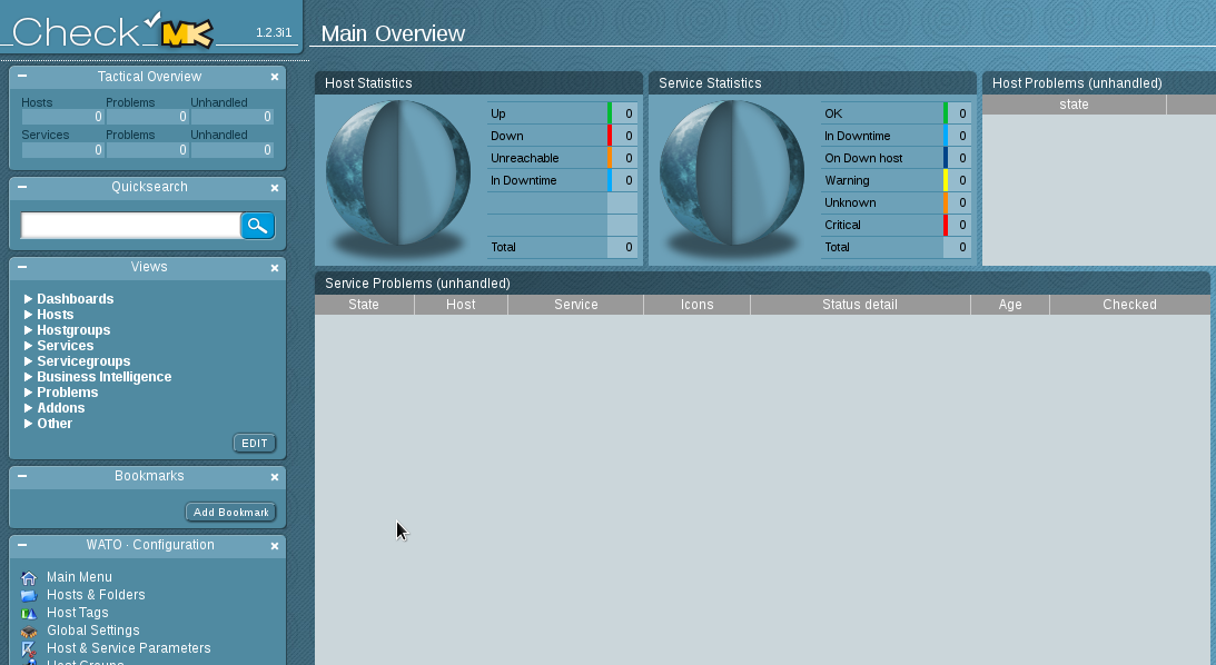
For this switch to the web interface Multisite for your OMD page (see figure The configuration is done by example on an empty sample site.).
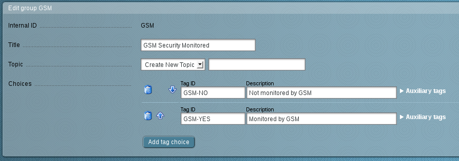
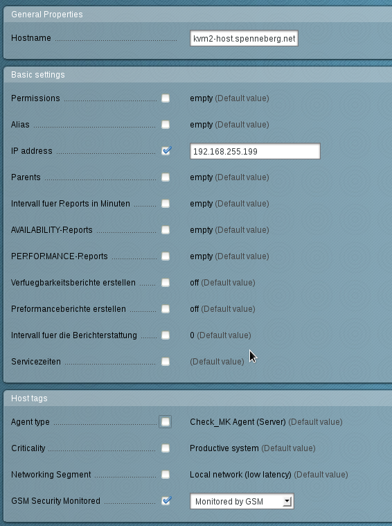
First create the host tag (figure The host tag labels the systems that are being monitored by the GSM.).
It labels the hosts that are also being scanned by the GSM appliance.
For this select Host Tags in the left menu and here create a new task.
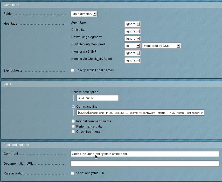
New create a new rule (figure This rule checks the status in the GSM for every host with the tag Monitored by GSM.), that analyzes the host tag.
For this select in the left menu in Host & Service Parameters the option Active Checks.
In the next menu select Classical Active and Passive Nagios Checks.
Then create a new rule (figure This rule checks the status in the GSM for every host with the tag Monitored by GSM.) in the current folder (Create Rule in Folder Main Directory).
Remember to use the following command:
$USER2$/check_omp -H <gsm -ip > -u <user > -w < password > -- status -T <report > \
--last -report -F $HOSTADDRESS$
Now the host has to be created or configure in a way that it has the respective host tag (see figure Every host scanned by the GSM now must have the tag.).
After the changes have been activated in the multisite (Activate Changes) the status information is available in the graphical interface.
So that the user name and password are not being displayed in the graphical interface they can be saved as variables to the file /opt/omd/sites/site/etc/nagios/resource.cfg:
############################################
# OMD settings, please use them to make your config
# portable, but dont change them
$USER1$=/omd/sites/produktiv/lib/nagios/plugins
$USER2$=/omd/sites/produktiv/local/lib/nagios/plugins
$USER3$=produktiv
$USER4$=/omd/sites/produktiv
############################################
# set your own macros here:
$USER5$=omd
$USER6$=kennwort
Now the username and the password can be replaced with the variables USER5 and USER6 in WATO.
22.4. Sourcefire Defence Center
The Sourcefire Intrusion Prevention System (IPS) is one of the leading solution for intrusion detection and defense in computer networks.
As a Network Intrusion Detection System (NIDS) it is being tasked with the discovery, alerting and the defense against attacks on the network.
For the Sourcefire IPS to correctly identify and classify attacks it requires as close as possible information about the systems in the network, the installed applications as well as their possible vulnerabilities.
For this purpose the Sourcefire System has its own asset database that can be augmented with information from the GSM.
Additionally the Sourcefire system can start an automatic scan if it suspects anything.
The connection methods are available:
- Automatic data transfer from the GSM to the NIDS/IDS
If the GSM and NIDS/IDS are configured respectively the data transfer from the GSM to the NIDS/IPS can be utilized easily, like any other alert functionality of the GSM.
After completion of the scan it will be forwarded as an alert to the NIDS/IPS in respect to the desired criteria.
If the scan task is being run automatically on a weekly basis you get a fully automated alerting and optimization system.
- Active control of the GSM by the NIDS/IPS
In the operation of the NIDS/IPS suspected incidents on systems with high risk can occur.
In such a case the NIDS/IPS can instruct the GSM to check the system .
To use the connection in the options 1 and 2 the GSM as well as the Sourcefire Defense Center must be prepared.
In the GSM a report plugin must be installed and on the Defense Center receiving the data must be enabled.
22.4.3. Configuration of Alerts on the GSM
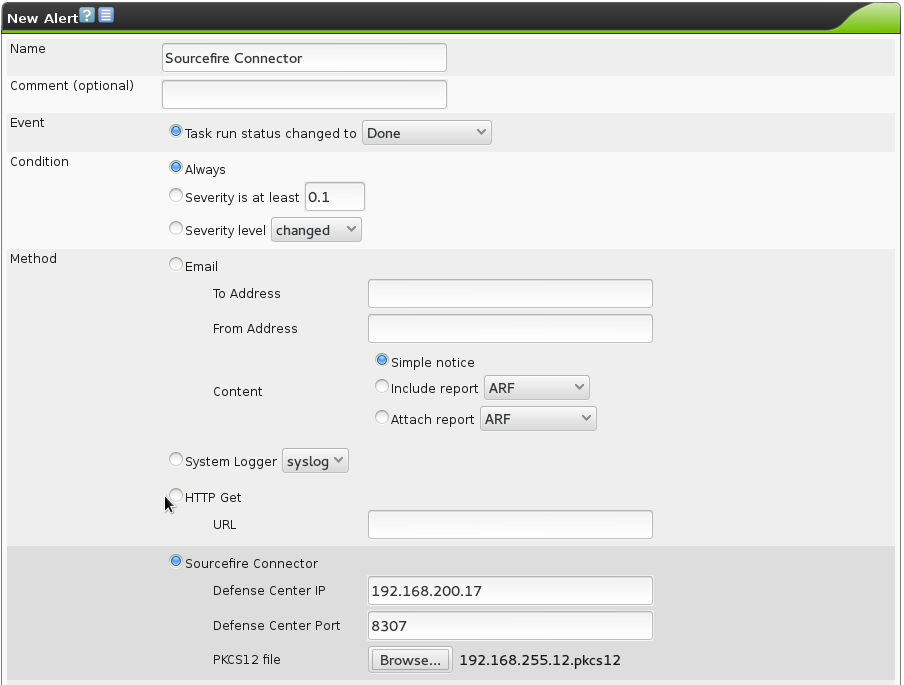
Now the respective Alerts must be set up on the GSM.
For this switch to Configuration/Alerts.
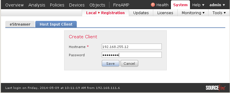
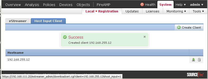
Enter the data of the Sourcefire system and the supply the PKCS12 file.
If a password was entered when the client was created the PKCS12 must be decrypted before loading it onto the GSM.
For this you can use the following command under Linux:
$ openssl pkcs12 -in encrypted.pkcs12 -nodes -out decrypted.pcks12
Enter Import Password : password
MAC verified OK
$
Footnotes

