This chapter provides specific setup guides and trouble shooting for the different GSM appliances:
The general setup which is the same for all GSM appliance models is described
in chapter Setup.
24.1. GSM ONE
This setup guide will show the steps required to put the GSM ONE appliance in to operation. You can use the following checklist to monitor your progress.
| Step |
Done |
|---|
| VirtualBox 4.3 installed |
|
| Integrity verification (optional) |
|
| Import of the OVA |
|
| Resources: 2 CPUs, 2GB Ram |
|
| Keyboard layout |
|
| IP address configuration |
|
| DNS configuration |
|
| Password change |
|
| Web admin account |
|
| SSL certificate |
|
| Readiness |
|
24.1.1. Requirements
This section lists the requirements for the successful deployment of the GSM ONE appliance.
Please ensure that all requirements are met.
24.1.1.1. Resources
The virtual appliance requires at least the following resources:
24.1.1.2. Supported Hypervisor
While the GSM ONE may be run on different hypervisors, only the following two hypervisors are currently supported:
- Oracle VirtualBox 4.3 on GNU/Linux
- Oracle VirtualBox 4.3 on Microsoft Windows
24.1.1.3. Verification of Integrity
The integrity of the virtual appliance may be verified. On request the Greenbone support provides an integrity checksum.
To request the checksum please contact the Greenbone support via email (emailto:support@greenbone.net).
Include your subscription number in the email.
The integrity checksum may be provided via phone or via support portal at https://support.greenbone.net. Please specify the preferred channel in the email.
The local verification of the checksum depends on the host operating system.
On Linux systems use the following command to calculate the checksum:
sha256sum GSM-ONE-3.1.19-18-gsf201599999.ova
On Windows systems you first have to install an appropiate program.
You may use rehash which can be found at http://rehash.sourceforge.net.
To calculate the checksum, use:
rehash.exe -none -sha256 C:\<path>\GSM-ONE-3.1.19-18-gsf201599999.ova
If the checksum does not match the checksum provide by the Greenbone support the virtual appliance has been modified and should not be used.
24.1.1.4. Deployment
Each GSM ONE is activated using a unique subscription key.
You may not clone the GSM ONE and use several instances in parallel.
This may result in inconsistencies and unwanted side effects.
24.1.2. Importing of the Virtual Appliance
The virtual appliances are being provided by Greenbone in the Open Virtualization Appliance (OVA) format.
These files are easily imported into VMWare or VirtualBox.
The following scenarios are supported by Greenbone:
- GSM ONE: Oracle VirtualBox 4.3 (Linux and Microsoft Windows)
- GSM 25V: ESXi 5.1
24.1.2.1. Import into VirtualBox
Install Oracle VirtualBox for your operating system.
VirtualBox is often included with Linux distributions.
Should this not be the case and for the different versions of Microsoft Windows, VirtualBox is available directly from Oracle http://virtualbox.org/wiki/Downloads.
Once installed, start VirtualBox.
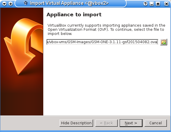
Now you can import the OVA-file via (see figure Import of the OVA-Appliance)
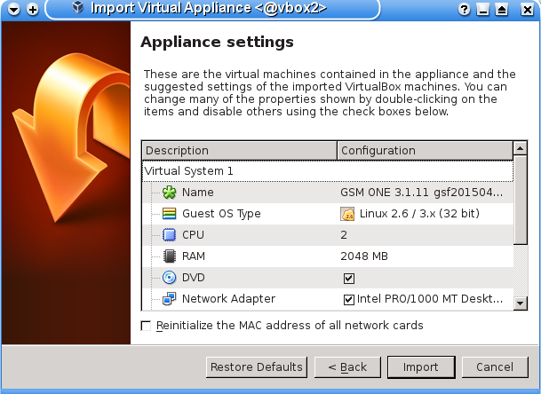
Confirm the configuration of the virtual machine in the following window (see figure Accepting the hardware configuration).
If possible, select 4096 MB RAM (memory) for optimal configuration of the virtual appliance.
Accept the remaining hardware settings.
The actual import can take up to 10 minutes.
Once imported you can start the virtual appliance.
24.1.2.2. General system setup
All GSM appliances share the same way of basic configuration and readiness check.
Please follow the steps described in chapter Setup and then continue with the next sections for logging in or for troubleshooting.
24.1.3. Login to the Webinterface
The main interface of the GSM is the web gui. To access the web gui use a current web browser and access https://<ip-of-the-gsm>/.
The IP address of the GSM is displayed at the login prompt of the console.
Login using the web admin you created during the setup.
24.1.4. GSM ONE troubleshooting
The following warnings and problems are known and depend on your environment:
- On Linux host systems VirtualBox may warn during the import that the Host-I/O-Cache is activated if the virtual image is stored on a xfs partition. This warning is expected and may be accepted.
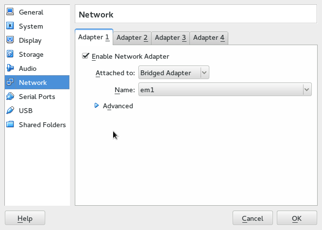
- On Linux host systems the warning “Failed to attach the network LUN (VERR_INTNET_FLT_IF_NOT_FOUND)” is displayed if the the virtual machine does not discover any network card. The network card within the VirtualBox hypervisor needs to be configured. Usually the default can be accepted.
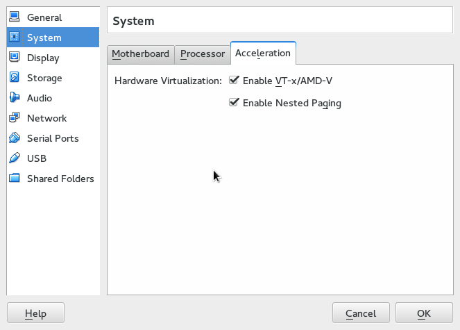
- If the warning “AMD-V is disabled in the BIOS. (VERR_SVM_DISABLED).” is displayed, you need to enable the option “VT-X/AMD-V” in the BIOS of your host. An alternative solution is disabling of the acceleration in the system configuration of the virtual machine.
24.2. GSM 25V
This setup guide will show the steps required to put the GSM 25V virtual appliance in to operation. You can use the following checklist to monitor your progress.
| Step |
Done |
|---|
| VMware ESXi 5.1 |
|
| Import of the OVA |
|
| Resources: 2 CPUs, 4GB Ram |
|
| Keyboard layout |
|
| IP address configuration |
|
| DNS configuration |
|
| Password change |
|
| Scan user account |
|
| SSL certificate |
|
| Master key download |
|
| Sensor setup on the master |
|
| Readiness |
|
24.2.1. Requirements
This section lists the requirements for the successful deployment of the GSM 25V appliance.
Please ensure that all requirements are met.
24.2.1.1. Resources
The virtual appliance requires at least the following resources:
24.2.1.2. Supported Hypervisor
The GSM 25V is only supported for the following hypervisor:
24.2.1.3. Deployment
You will receive the GSM 25V as a VM image in OVA format. Usually the image does not include the latest updates and feeds. You will need to update and synchronize the current feed using the master GSM after deployment.
Each GSM 25V requires a unique subscription key. This key is not pre-installed nad needs to be installed manually before using the GSM 25V.
You may not clone the GSM 25V and use several instances in parallel with the same subscription key.
This may result in inconsistencies and unwanted side effects.
24.2.2. Importing of the Virtual Appliance
The virtual appliances are being provided by Greenbone in the Open Virtualization Appliance (OVA) format.
These files are easily imported into VMWare or VirtualBox.
The following scenarios are supported by Greenbone:
- GSM ONE: Oracle VirtualBox 4.3 (Linux and Microsoft Windows)
- GSM 25V: ESXi 5.1
24.2.2.1. Import into ESXi 5.1
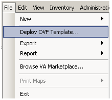
Start the VMware ESXi 5.1 client.
- Once the import is finished you may select power on the virtual appliance.
24.2.2.2. General system setup
All GSM appliances share the same way of basic configuration and readiness check.
But being a sole sensor the GSM 25V differs in some steps from the other appliances:
- You do not add a web admin but a scan user account.
- You need to exchange the masterkey with the sensor.
Please follow the steps described in chapter Setup. Please remember to add the scan user account instead of a web admin account and then continue with the section Sensor to exchange the keys with the master.
The GSM 25V sensor does not offer any web interface. You can login to the sensor using the console and SSH from the master. The sensor is solely managed from the master.
If the communication between the master and the sensor fails, you might need to adjust the rule-set of any internal firewall governing the network connection.
24.3. GSM 25
This setup guide will show the steps required to put a GSM 25 sensor appliance in to operation. You can use the following checklist to monitor your progress.
| Step |
Done |
|---|
| Powersupply |
|
| Serial console cable / USB converter |
|
| Putty/Screen setup |
|
| Keyboard layout |
|
| IP address configuration |
|
| DNS configuration |
|
| Password change |
|
| Scan user account |
|
| SSL certificate |
|
| Master key download |
|
| Sensor setup on the master |
|
| Readiness |
|
24.3.1. Installation
The appliance GSM 25 is 19” mountable and requires 1 rack unit (RU).
The optional RACKMOUNT25 kit provides the racking brackets for installation in a 19” rack. For stand-alone operation you will find 4 self-sticking rubber pads to be mounted on the corresponding bottom side embossments.
For cabling the GSM 25 appliance has corresponding connectors at the back:
- back:
- Power supply +12V DC (one), external power supply and suitable cable enclosed
- Network access (LAN1)
- RS-232 console port, suitable cable is enclosed
- Reset button
For the installation you have to use a terminal application and a serial cable to establish a connection.
24.3.2. Serial Port
To utilize the serial port use the enclosed console cable.
Alternatively you can use a blue Cisco console cable (rollover-cable).
Should your system not come with a serial port you will require a USB-to-Serial adapter.
Ensure the use of a quality adapter.
Many cheap adapters can cause errors with the serial protocol.
Additionally such adapters might not be compatible with the drivers that come with Microsoft Windows operating systems.
To access the serial port you require a terminal application.
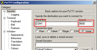
The application needs to be configured to a speed of 9600 Bits/s (Baud).
In Linux the command line command screen can be used.
It is sufficient to run the command providing the serial port.
screen /dev/ttyS0  #(for serial port)
screen /dev/ttyUSB0 #(for USB adapter)
Sometimes it does not work with the first serial port.
You have to experiment with the number (0, 1 or 2).
You can quit the command by entering CTRL-a \.
When starting the command it might be necessary to hit RETURN several times to get a command prompt.
In Windows you can use the Putty application.
After starting putty you will select the options as per Figure Setting up the serial port in Putty.
Select the appropriate serial port also.
24.3.3. Startup
Once the appliance is fully wired and you are connected to the appliance via the console cable and have setup the terminal application (putty, screen or similar) you can power on the appliance.
The appliance will boot and depending on the exact model the first messages will be displayed in the terminal application after a short time period.
24.3.3.1. General system setup
All GSM appliances share the same way of basic configuration and readiness check.
But being a sole sensor the GSM 25 differs in some steps from the other appliances:
- You do not add a web admin but a scan user account.
- You need to exchange the masterkey with the sensor.
Please follow the steps described in chapter Setup. Please remember to add the scan user account instead of a web admin account and then continue with the section Sensor to exchange the keys with the master.
The GSM 25 sensor does not offer any web interface. You can login to the sensor using the console and SSH from the master. The sensor is solely managed from the master.
If the communication between the master and the sensor fails, you might need to adjust the rule-set of any internal firewall governing the network connection.
24.4. GSM 100
This setup guide will show the steps required to put a GSM 100 appliance in to operation. You can use the following checklist to monitor your progress.
| Step |
Done |
|---|
| Powersupply |
|
| Serial console cable / USB converter |
|
| Putty/Screen setup |
|
| Keyboard layout |
|
| IP address configuration |
|
| DNS configuration |
|
| Password change |
|
| Web admin account |
|
| SSL certificate |
|
| Readiness |
|
24.4.1. Installation
The appliance GSM 100 is 19” mountable and requires 1 rack unit (RU).
The optional RACKMOUNT100 kit provides the racking brackets for installation in a 19” rack. For stand-alone operation you will find 4 self-sticking rubber pads to be mounted on the corresponding bottom side embossments.
For cabling the GSM 100 appliance has corresponding connectors at the back:
- back:
- Power supply +12V DC (one), external power supply and suitable cable enclosed
- Network access (LAN1)
- RS-232 console port, suitable cable is enclosed
- Reset button
For the installation you have to use a terminal application and a serial cable to establish a connection.
24.4.2. Serial Port
To utilize the serial port use the enclosed console cable.
Alternatively you can use a blue Cisco console cable (rollover-cable).
Should your system not come with a serial port you will require a USB-to-Serial adapter.
Ensure the use of a quality adapter.
Many cheap adapters can cause errors with the serial protocol.
Additionally such adapters might not be compatible with the drivers that come with Microsoft Windows operating systems.
To access the serial port you require a terminal application.
The application needs to be configured to a speed of 9600 Bits/s (Baud).
In Linux the command line command screen can be used.
It is sufficient to run the command providing the serial port.
screen /dev/ttyS0  #(for serial port)
screen /dev/ttyUSB0 #(for USB adapter)
Sometimes it does not work with the first serial port.
You have to experiment with the number (0, 1 or 2).
You can quit the command by entering CTRL-a \.
When starting the command it might be necessary to hit RETURN several times to get a command prompt.
In Windows you can use the Putty application.
After starting putty you will select the options as per Figure Setting up the serial port in Putty.
Select the appropriate serial port also.
24.4.3. Startup
Once the appliance is fully wired and you are connected to the appliance via the console cable and have setup the terminal application (putty, screen or similar) you can power on the appliance.
The appliance will boot and depending on the exact model the first messages will be displayed in the terminal application after a short time period.
24.4.3.1. General system setup
All GSM appliances share the same way of basic configuration and readiness check.
Please follow the steps described in chapter Setup and then continue with the next sections for logging in.
24.4.4. Login to the Webinterface
The main interface of the GSM is the web gui. To access the web gui use a current web browser and access https://<ip-of-the-gsm>/.
The IP address of the GSM is displayed at the login prompt of the console.
Login using the web admin you created during the setup.
24.5. GSM 500/510/550
This setup guide will show the steps required to put a GSM 500, 510 or 550 appliance in to operation. You can use the following checklist to monitor your progress.
| Step |
Done |
|---|
| Powersupply |
|
| Serial console cable / USB converter |
|
| Putty/Screen setup |
|
| Firmware check (>= 2.0) |
|
| Keyboard layout |
|
| IP address configuration |
|
| DNS configuration |
|
| Password change |
|
| Web admin account |
|
| SSL certificate |
|
| Readiness |
|
24.5.1. Installation
The appliances GSM 500, GSM 510 and GSM 550 are 19” mountable and require 1 rack unit (RU).
For installation in a 19” this equipment comes with the respective racking brackets.
For cabling GSM 500, GSM 510 and GSM 550 appliances have corresponding connectors at the front and back:
- back:
- Power supply (one)
- VGA-monitor
- Keyboard via USB
- Serial Console
- front
- Keyboard via USB
- Network port eth0
- RS-232 console port (|O|O|O), Cisco compatible, suitable cable is enclosed
For the installation you have to use a terminal application and a console cable to establish a connection.
24.5.2. Serial Port
To utilize the serial port use the enclosed console cable.
Alternatively you can use a blue Cisco console cable (rollover-cable).
Should your system not come with a serial port you will require a USB-to-Serial adapter.
Ensure the use of a quality adapter.
Many cheap adapters can cause errors with the serial protocol.
Additionally such adapters might not be compatible with the drivers that come with Microsoft Windows operating systems.
To access the serial port you require a terminal application.
The application needs to be configured to a speed of 9600 Bits/s (Baud).
In Linux the command line command screen can be used.
It is sufficient to run the command providing the serial port.
screen /dev/ttyS0  #(for serial port)
screen /dev/ttyUSB0 #(for USB adapter)
Sometimes it does not work with the first serial port.
You have to experiment with the number (0, 1 or 2).
You can quit the command by entering CTRL-a \.
When starting the command it might be necessary to hit RETURN several times to get a command prompt.
In Windows you can use the Putty application.
After starting putty you will select the options as per Figure Setting up the serial port in Putty.
Select the appropriate serial port also.
24.5.3. Startup
Once the appliance is fully wired and you are connected to the appliance via the console cable and have setup the terminal application (putty, screen or similar) you can power on the appliance.
The appliance will boot and depending on the exact model the first messages will be displayed in the terminal application after a short time period.
24.5.3.1. Firmware Notice
The appliances GSM 500, GSM 510 and GSM 550 are first generation devices. These devices were shipped with older firmware images which needs to be upgraded before the appliances are put into production. If the displayed flash version is < 2.0 please contact the Greenbone support (mailto:support@greenbone.net) before continuing!
24.5.3.2. General system setup
All GSM appliances share the same way of basic configuration and readiness check.
Please follow the steps described in chapter Setup and then continue with the next sections for logging in.
24.5.4. Login to the Webinterface
The main interface of the GSM is the web gui. To access the web gui use a current web browser and access https://<ip-of-the-gsm>/.
The IP address of the GSM is displayed at the login prompt of the console.
Login using the web admin you created during the setup.
24.6. GSM 400/600/650
This setup guide will show the steps required to put a GSM 400, 600 or 650 appliance in to operation. You can use the following checklist to monitor your progress.
| Step |
Done |
|---|
| Powersupply |
|
| Serial console cable / USB converter |
|
| Putty/Screen setup |
|
| Keyboard layout |
|
| IP address configuration |
|
| DNS configuration |
|
| Password change |
|
| Web admin account |
|
| SSL certificate |
|
| Readiness |
|
24.6.1. Installation
The appliances GSM 400, GSM 600 and GSM 650 are 19” mountable and require 1 rack unit (RU).
For installation in a 19” this equipment comes with the respective racking brackets.
For cabling GSM 400, GSM 600 and GSM 650 appliances have corresponding connectors at the front and back:
- back:
- Power supply (one)
- VGA-monitor
- Keyboard via USB
- Serial Console
- front
- Keyboard via USB
- Network port eth0
- RS-232 console port (|O|O|O), Cisco compatible, suitable cable is enclosed
For the installation you have to use a terminal application and a console cable to establish a connection.
24.6.2. Serial Port
To utilize the serial port use the enclosed console cable.
Alternatively you can use a blue Cisco console cable (rollover-cable).
Should your system not come with a serial port you will require a USB-to-Serial adapter.
Ensure the use of a quality adapter.
Many cheap adapters can cause errors with the serial protocol.
Additionally such adapters might not be compatible with the drivers that come with Microsoft Windows operating systems.
To access the serial port you require a terminal application.
The application needs to be configured to a speed of 9600 Bits/s (Baud).
In Linux the command line command screen can be used.
It is sufficient to run the command providing the serial port.
screen /dev/ttyS0  #(for serial port)
screen /dev/ttyUSB0 #(for USB adapter)
Sometimes it does not work with the first serial port.
You have to experiment with the number (0, 1 or 2).
You can quit the command by entering CTRL-a \.
When starting the command it might be necessary to hit RETURN several times to get a command prompt.
In Windows you can use the Putty application.
After starting putty you will select the options as per Figure Setting up the serial port in Putty.
Select the appropriate serial port also.
24.6.3. Startup
Once the appliance is fully wired and you are connected to the appliance via the console cable and have setup the terminal application (putty, screen or similar) you can power on the appliance.
The appliance will boot and depending on the exact model the first messages will be displayed in the terminal application after a short time period.
24.6.3.1. General system setup
All GSM appliances share the same way of basic configuration and readiness check.
Please follow the steps described in chapter Setup and then continue with the next sections for logging in.
24.6.4. Login to the Webinterface
The main interface of the GSM is the web gui. To access the web gui use a current web browser and access https://<ip-of-the-gsm>/.
The IP address of the GSM is displayed at the login prompt of the console.
Login using the web admin you created during the setup.
24.7. GSM 5300/6400
This setup guide will show the steps required to put a GSM 5300 or 6400 appliance in to operation. You can use the following checklist to monitor your progress.
| Step |
Done |
|---|
| Powersupply (2 connectors) |
|
| Serial console cable / USB converter |
|
| Putty/Screen setup |
|
| Keyboard layout |
|
| IP address configuration |
|
| DNS configuration |
|
| Password change |
|
| Web admin account |
|
| SSL certificate |
|
| Readiness |
|
24.7.1. Installation
The appliances GSM 5300 and GSM 6400 are 19” mountable and require 2 rack units (RU).
For installation in a 19” this equipment comes with the respective racking brackets.
For cabling GSM 5300 and GSM 6400 appliances have corresponding connectors at the front and back:
- back:
- Power supply (two)
- VGA-monitor
- front
- Keyboard via USB
- Network port labeled “MGMT” (eth0)
- RS-232 console port (|O|O|O), Cisco compatible, suitable cable is enclosed
For the installation you have to use a terminal application and a console cable to establish a connection.
24.7.2. Serial Port
To utilize the serial port use the enclosed console cable.
Alternatively you can use a blue Cisco console cable (rollover-cable).
Should your system not come with a serial port you will require a USB-to-Serial adapter.
Ensure the use of a quality adapter.
Many cheap adapters can cause errors with the serial protocol.
Additionally such adapters might not be compatible with the drivers that come with Microsoft Windows operating systems.
To access the serial port you require a terminal application.
The application needs to be configured to a speed of 9600 Bits/s (Baud).
In Linux the command line command screen can be used.
It is sufficient to run the command providing the serial port.
screen /dev/ttyS0  #(for serial port)
screen /dev/ttyUSB0 #(for USB adapter)
Sometimes it does not work with the first serial port.
You have to experiment with the number (0, 1 or 2).
You can quit the command by entering CTRL-a \.
When starting the command it might be necessary to hit RETURN several times to get a command prompt.
In Windows you can use the Putty application.
After starting putty you will select the options as per Figure Setting up the serial port in Putty.
Select the appropriate serial port also.
24.7.3. Startup
Once the appliance is fully wired and you are connected to the appliance via the console cable and have setup the terminal application (putty, screen or similar) you can power on the appliance.
The appliance will boot and depending on the exact model the first messages will be displayed in the terminal application after a short time period.
24.7.3.1. General system setup
All GSM appliances share the same way of basic configuration and readiness check.
Please follow the steps described in chapter Setup and then continue with the next sections for logging in.
24.7.4. Login to the Webinterface
The main interface of the GSM is the web gui. To access the web gui use a current web browser and access https://<ip-of-the-gsm>/.
The IP address of the GSM is displayed at the login prompt of the console.
Login using the web admin you created during the setup.

