
This section describes how the Open vSwitch plug-in implements the Networking abstractions.
This example uses VLAN segmentation on the switches
to isolate tenant networks. This configuration labels the
physical network associated with the public network as
physnet1, and the physical network
associated with the data network as
physnet2, which leads to the following
configuration options in ovs_neutron_plugin.ini:
[ovs]
tenant_network_type = vlan
network_vlan_ranges = physnet2:100:110
integration_bridge = br-int
bridge_mappings = physnet2:br-eth1
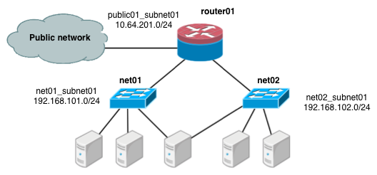
The first scenario has two private networks (net01, and
net02), each with one subnet
(net01_subnet01: 192.168.101.0/24,
net02_subnet01, 192.168.102.0/24). Both private networks are
attached to a router that connects them to the public network (10.64.201.0/24).
Under the service tenant, create the shared router, define the
public network, and set it as the default gateway of the
router
$ tenant=$(keystone tenant-list | awk '/service/ {print $2}')
$ neutron router-create router01
$ neutron net-create --tenant-id $tenant public01 \
          --provider:network_type flat \
          --provider:physical_network physnet1 \
          --router:external=True
$ neutron subnet-create --tenant-id $tenant --name public01_subnet01 \
          --gateway 10.64.201.254 public01 10.64.201.0/24 --disable-dhcp
$ neutron router-gateway-set router01 public01
Under the demo user tenant, create the private network
net01 and corresponding subnet, and connect it to the
router01 router. Configure it to use VLAN ID 101 on the
physical
switch.
$ tenant=$(keystone tenant-list|awk '/demo/ {print $2}'
$ neutron net-create --tenant-id $tenant net01 \
          --provider:network_type vlan \
          --provider:physical_network physnet2 \
          --provider:segmentation_id 101
$ neutron subnet-create --tenant-id $tenant --name net01_subnet01 net01 192.168.101.0/24
$ neutron router-interface-add router01 net01_subnet01
Similarly, for net02, using VLAN ID 102 on the physical
switch:
$ neutron net-create --tenant-id $tenant net02 \
          --provider:network_type vlan \
          --provider:physical_network physnet2 \
          --provider:segmentation_id 102
$ neutron subnet-create --tenant-id $tenant --name net02_subnet01 net02 192.168.102.0/24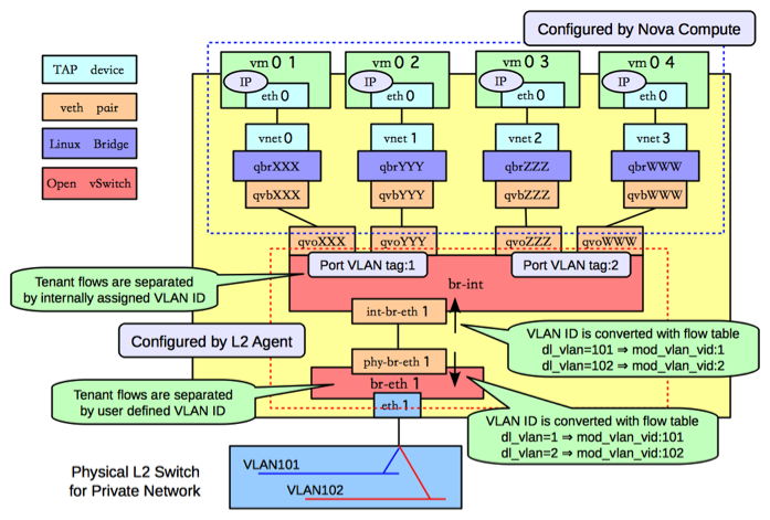
$ neutron router-interface-add router01 net02_subnet01The following figure shows how to configure various Linux networking devices on the compute host:

![[Note]](../common/images/admon/note.png) | Note |
|---|---|
There are four distinct type of virtual networking devices: TAP devices,
veth pairs, Linux bridges, and Open vSwitch bridges. For an ethernet frame to travel
from |
A TAP device, such as vnet0
is how hypervisors such as KVM and Xen implement a virtual network interface card
(typically called a VIF or vNIC). An ethernet frame sent to a TAP device is received
by the guest operating system.
A veth pair is a pair of directly connected virtual network interfaces. An ethernet frame sent to one end of a veth pair is received by the other end of a veth pair. Networking uses veth pairs as virtual patch cables to make connections between virtual bridges.
A Linux bridge behaves like a hub: you can connect multiple (physical or virtual) network interfaces devices to a Linux bridge. Any ethernet frames that come in from one interface attached to the bridge is transmitted to all of the other devices.
An Open vSwitch bridge behaves like a virtual switch: network interface devices connect to Open vSwitch bridge's ports, and the ports can be configured much like a physical switch's ports, including VLAN configurations.
The br-int Open vSwitch bridge is the integration bridge: all
guests running on the compute host connect to this bridge. Networking
implements isolation across these guests by configuring the
br-int ports.
The br-eth1 bridge provides connectivity to the physical
network interface card, eth1. It connects to the integration
bridge by a veth pair: (int-br-eth1, phy-br-eth1).
In this example, net01 and net02 have VLAN ids of 1 and 2, respectively. However,
the physical network in our example only supports VLAN IDs in the range 101 through 110. The
Open vSwitch agent is responsible for configuring flow rules on
br-int and br-eth1 to do VLAN translation.
When br-eth1 receives a frame marked with VLAN ID 1 on the port
associated with phy-br-eth1, it modifies the VLAN ID in the frame
to 101. Similarly, when br-int receives a frame marked with VLAN ID 101 on the port
associated with int-br-eth1, it modifies the VLAN ID in the frame
to 1.
Ideally, the TAP device vnet0 would be connected directly to
the integration bridge, br-int. Unfortunately, this isn't
possible because of how OpenStack security groups are currently implemented.
OpenStack uses iptables rules on the TAP devices such as
vnet0 to implement security groups, and Open vSwitch
is not compatible with iptables rules that are applied directly on TAP
devices that are connected to an Open vSwitch port.
Networking uses an extra Linux bridge and a veth pair as a workaround for this
issue. Instead of connecting vnet0 to an Open vSwitch
bridge, it is connected to a Linux bridge,
qbr. This bridge is
connected to the integration bridge, XXXbr-int, through the
(qvb veth pair.XXX,
qvoXXX)
The network host runs the neutron-openvswitch-plugin-agent, the neutron-dhcp-agent, neutron-l3-agent, and neutron-metadata-agent services.
On the network host, assume that eth0 is connected to the external network, and
eth1 is connected to the data network, which leads to the following configuration
in the
ovs_neutron_plugin.ini file:
[ovs]
tenant_network_type = vlan
network_vlan_ranges = physnet2:101:110
integration_bridge = br-int
bridge_mappings = physnet1:br-ex,physnet2:br-eth1
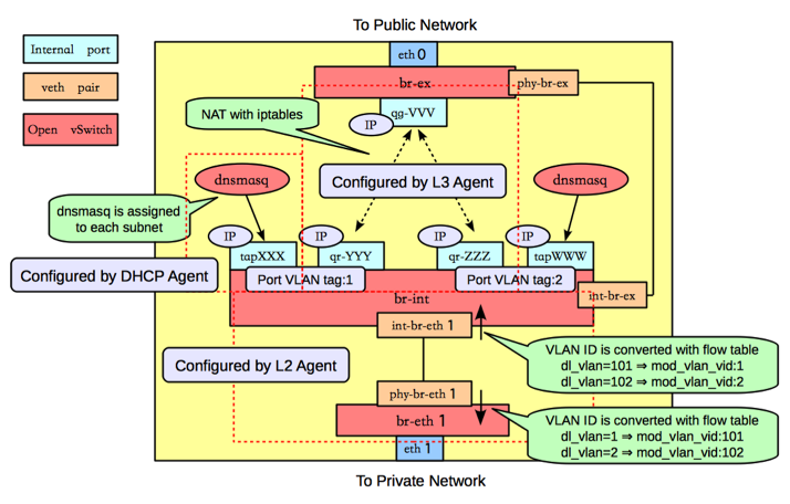
The following figure shows the network devices on the network host:
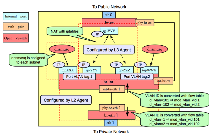
As on the compute host, there is an Open vSwitch integration bridge
(br-int) and an Open vSwitch bridge connected to the data
network (br-eth1), and the two are connected by a veth pair, and
the neutron-openvswitch-plugin-agent configures the ports on both switches to do
VLAN translation.
An additional Open vSwitch bridge, br-ex,
connects to the physical interface that is connected to the external network. In
this example, that physical interface is eth0.
| Note |
|---|---|
While the integration bridge and the external bridge are connected by
a veth pair |
The network host uses Open vSwitch internal
ports. Internal ports enable you to assign one or more IP
addresses to an Open vSwitch bridge. In previous example, the
br-int bridge has four internal ports:
tap,
XXXqr-,
YYYqr-, and
ZZZtap. Each internal
port has a separate IP address associated with it. An internal port,
WWWqg-VVV, is on the br-ex
bridge.
By default, The Networking DHCP agent uses a process called dnsmasq to provide
DHCP services to guests. Networking must create an internal port for each
network that requires DHCP services and attach a dnsmasq process to that
port. In the previous example, the
tap interface is on
XXXnet01_subnet01, and the
tap interface is on
WWWnet02_subnet01.
The Networking L3 agent uses Open vSwitch internal ports to implement routing and
relies on the network host to route the packets across the interfaces. In
this example, the qr-YYY interface is on
net01_subnet01 and has the IP address
192.168.101.1/24. The qr-,
interface is on ZZZnet02_subnet01 and has the IP address
192.168.102.1/24. The
qg- interface has
the IP address VVV10.64.201.254/24. Because each of these
interfaces is visible to the network host operating system, the network host
routes the packets across the interfaces, as long as an administrator has
enabled IP forwarding.
The L3 agent uses iptables to implement floating IPs to do the network address translation (NAT).
One problem with using the host to implement routing is that one of the
Networking subnets might overlap with one of the physical networks that the
host uses. For example, if the management network is implemented on
eth2 and also happens to be on the
192.168.101.0/24 subnet, routing problems will occur
because the host can't determine whether to send a packet on this subnet to
qr-YYY or eth2. If end users are
permitted to create their own logical networks and subnets, you must design
the system so that such collisions do not occur.
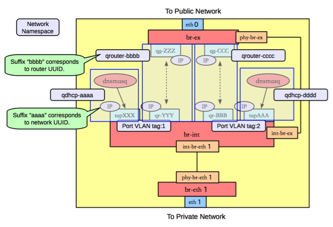
Networking uses Linux network namespaces to prevent collisions between the physical networks on the network host, and the logical networks used by the virtual machines. It also prevents collisions across different logical networks that are not routed to each other, as the following scenario shows.
A network namespace is an isolated environment with its own networking stack. A network namespace has its own network interfaces, routes, and iptables rules. Consider it a chroot jail, except for networking instead of for a file system. LXC (Linux containers) use network namespaces to implement networking virtualization.
Networking creates network namespaces on the network host to avoid subnet collisions.
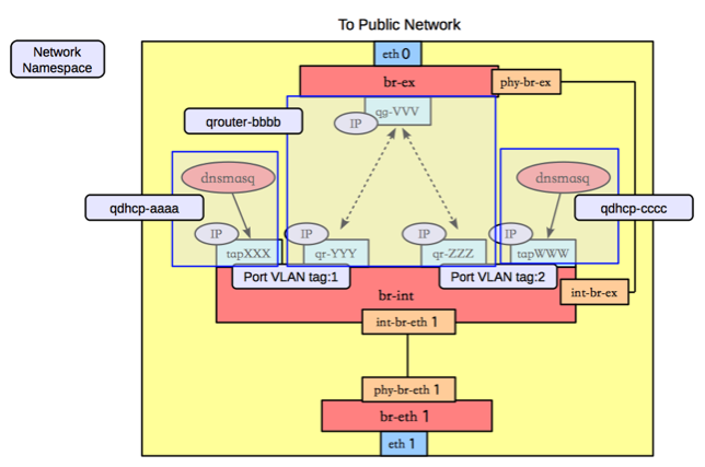
In this example, there are three network namespaces, as shown in the figure above:
qdhcp-: contains theaaatapinterface and the dnsmasq process that listens on that interface to provide DHCP services forXXXnet01_subnet01. This allows overlapping IPs betweennet01_subnet01and any other subnets on the network host.qrouter-: contains thebbbbqr-,YYYqr-, andZZZqg-interfaces, and the corresponding routes. This namespace implementsVVVrouter01in our example.qdhcp-: contains theccctapinterface and the dnsmasq process that listens on that interface, to provide DHCP services forWWWnet02_subnet01. This allows overlapping IPs betweennet02_subnet01and any other subnets on the network host.
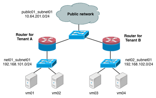
In this scenario, tenant A and tenant B each have a network with one subnet and one router that connects the tenants to the public Internet.
Under the service tenant, define the public
network:
$ tenant=$(keystone tenant-list | awk '/service/ {print $2}')
$ neutron net-create --tenant-id $tenant public01 \
          --provider:network_type flat \
          --provider:physical_network physnet1 \
          --router:external=True
$ neutron subnet-create --tenant-id $tenant --name public01_subnet01 \
          --gateway 10.64.201.254 public01 10.64.201.0/24 --disable-dhcp
Under the tenantA user tenant, create the tenant router and set
its gateway for the public
network.
$ tenant=$(keystone tenant-list|awk '/tenantA/ {print $2}')
$ neutron router-create --tenant-id $tenant router01
$ neutron router-gateway-set router01 public01
Then, define private network net01 using VLAN ID 101 on the
physical switch, along with its subnet, and connect it to the router.
$ neutron net-create --tenant-id $tenant net01 \
          --provider:network_type vlan \
          --provider:physical_network physnet2 \
          --provider:segmentation_id 101
$ neutron subnet-create --tenant-id $tenant --name net01_subnet01 net01 192.168.101.0/24
$ neutron router-interface-add router01 net01_subnet01
Similarly, for tenantB, create a router and another network,
using VLAN ID 102 on the physical
switch:
$ tenant=$(keystone tenant-list|awk '/tenantB/ {print $2}')
$ neutron router-create --tenant-id $tenant router02
$ neutron router-gateway-set router02 public01
$ neutron net-create --tenant-id $tenant net02 \
          --provider:network_type vlan \
          --provider:physical_network physnet2 \
          --provider:segmentation_id 102
$ neutron subnet-create --tenant-id $tenant --name net02_subnet01 net01 192.168.102.0/24
$ neutron router-interface-add router02 net02_subnet01The following figure shows how to configure Linux networking devices on the compute host:
| Note |
|---|---|
The compute host configuration resembles the configuration in scenario 1. However, in scenario 1, a guest connects to two subnets while in this scenario, the subnets belong to different tenants. |
The following figure shows the network devices on the network host for the second scenario.
In this configuration, the network namespaces are organized to isolate the two subnets from each other as shown in the following figure.
In this scenario, there are four network namespaces
(qhdcp-,
aaaqrouter-,
bbbbqrouter-, and
ccccqhdcp-), instead of three.
Since there is no connectivity between the two networks, and so each router is
implemented by a separate namespace.dddd
Tunneling encapsulates network traffic between physical Networking hosts and allows VLANs to span multiple physical hosts. Instances communicate as if they share the same layer 2 network. Open vSwitch supports tunneling with the VXLAN and GRE encapsulation protocols.
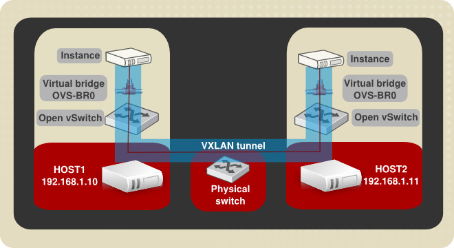
This diagram shows two instances running on separate hosts connected by a VXLAN tunnel. The required physical and virtual components are also illustrated. The following procedure creates a VXLAN or GRE tunnel between two Open vSwitches running on separate Networking hosts:
Procedure 7.16. Example tunnel configuration
Create a virtual bridge named OVS-BR0 on each participating host:
ovs-vsctl add-br OVS-BR0Create a tunnel to link the OVS-BR0 virtual bridges. Run the ovs-vsctl command on HOST1 to create the tunnel and link it to the bridge on HOST2:
GRE tunnel command:
ovs-vsctl add-port OVS-BR0 gre1 -- set Interface gre1 type=gre options:remote_ip=192.168.1.11VXLAN tunnel command:
ovs-vsctl add-port OVS-BR0 vxlan1 -- set Interface vxlan1 type=vxlan options:remote_ip=192.168.1.11Run the ovs-vsctl command on HOST1 to create the tunnel and link it to the bridge on HOST2.
GRE tunnel command:
ovs-vsctl add-port OVS-BR0 gre1 -- set Interface gre1 type=gre options:remote_ip=192.168.1.10VXLAN tunnel command:
ovs-vsctl add-port OVS-BR0 vxlan1 -- set Interface vxlan1 type=vxlan options:remote_ip=192.168.1.10
Successful completion of these steps results in the two instances sharing a layer 2 network.
